

Page 1
Issue 2016-05-16 ab V2.60
Datasheet 1.10-60.015-01-EN
Product Description
RBW322-FTL
RBW322-FTL room control module
SolarFunk room control module with smart communication management
Application
Solar-powered room control module with LCD and controls, with smart communication
management for measuring room temperature and for wireless transmission of
measured values, occupancy, setpoint and weekly schedule.
The RBW322-FTL supports the EnOcean radio standard ISO/IEC 14543-3-10 for direct
communication with the technoLink MD15-FTL-xx radio small actuator or an EnOcean
gateway. It uses EEP D2-10-01* for connection to an EnOcean gateway.
In combination with the MD15-FTL-xx, the RBW322-FTL constitutes a functional unit
for controlling the room temperature.
* You can find information about the protocol description on the EnOcean
Technology website http://www.enocean-alliance.org/en/enocean_standard/
Content Page
Important Information Regarding Product Safety ..................................................................................................2
Technical Data.....................................................................................................................................................3
Dimensions..........................................................................................................................................................4
Radio Interface ....................................................................................................................................................5
Installation............................................................................................................................................................6
General installation instructions...........................................................................................................................6
Mounting ................................................................................................................................................................7
Removal.................................................................................................................................................................8
Indicators on the display ........................................................................................................................................9
Operation, display and settings ...........................................................................................................................10
Switching on the device.....................................................................................................................................11
Summer mode .....................................................................................................................................................11
Manually switching between comfort and economy mode ..................................................................................11
Operating level.....................................................................................................................................................12
Setting the setpoint............................................................................................................................................12
Configuration level ...............................................................................................................................................12
Setting party mode (usage time extension) .......................................................................................................13
Setting vacation mode .......................................................................................................................................14
Setting the weekly schedule ..............................................................................................................................15
Setting the setpoints for comfort mode and economy mode .............................................................................16
Setting the time and date...................................................................................................................................16
Setting the time, temperature or setpoint for the initial display ..........................................................................17
Setting the 12/24 hour display ...........................................................................................................................17
Switching the temperature scale °C/°F..............................................................................................................17
Service level ........................................................................................................................................................18
Teaching in the MD15-FTL-xx wireless partner and EnOcean gateway on the RBW322-FTL ...........................20
Deleting the wireless partner on the RBW322-FTL .............................................................................................22
Operating and Malfunction Messages .................................................................................................................22
Änderungen vorbehalten - Contents subject to change - Sous réserve de modifications - Reservado el derecho a modificación - Wijzigingen
voorbehouden - Con riserva di modifiche - Innehåll som skall ändras - Změny vyhrazeny - Zmiany zastrzeżone - Возможны изменения A változtatások jogát fenntartjuk - ؍⮉ᵚ㓿䙊⸕㘼᭩ࣘⲴᵳ࣋
Kieback&Peter GmbH & Co. KG
Tempelhofer Weg 50, 12347 Berlin/Germany
Telefon: +49 30 60095-0, Telefax: +49 30 60095-164
www.kieback-peter.de, info@kieback-peter.com
A
Page 2

Datasheet 1.10-60.015-01-EN Issue 2016-05-16 ab V2.60
Product DescriptionRBW322-FTL
Important Information Regarding Product Safety
Safety Instructions
This data sheet contains information on installing and commissioning the product "RBW322-FTL".
Each person who carries out work on this product must have read and understood this data sheet. If
you have any questions that are not resolved by this data sheet, you can obtain further information
from the supplier or manufacturer.
If the product is not used in accordance with this data sheet, the protection provided will be impaired.
Applicable regulations must be observed when installing and using the device. Within the EU, these
include regulations regarding occupational safety and accident prevention as well as those from the
VDE (Association for Electrical, Electronic & Information Technologies). If the device is used in other
countries, it is the responsibility of the system installer or operator to comply with local regulations.
Mounting, installation and commissioning work on the devices may only be carried out by qualified
technicians. Qualified technicians are persons who are familiar with the described product and who
can assess given tasks and recognize possible dangers due to technical training, knowledge and
experience as well as knowledge of the appropriate regulations.
Legend
WARNING
Indicates a hazard of medium risk which can result in death or severe bodily injury if it is not avoided.
!
CAUTION
Indicates a hazard of low risk which can result in minor or medium bodily injury if it is not avoided.
NOTICE
Indicates a hazard of medium risk which can result in material damage or malfunctions if it is not
avoided.
NOTE
Indicates additional information that can simplify the work with the product for you.
Notes on Disposal
For disposal, the product is considered waste from electrical and electronic equipment (electronic
waste) and must not be disposed of as household waste. Special treatment for specific components
may be legally binding or ecologically sensible. The local and currently applicable legislation must be
observed.
A
Page 2 / 24
Page 3

Issue 2016-05-16 ab V2.60
Item
RBW322-FTL SolarFunk room control module
Technical Data
Power supply Dual power supply consisting of a solar cell and an internal energy
Measured quantity Room temperature in homes or offices
Measuring system Integrated digital sensor
Temperature units Can be set to °C or °F
Measuring range 0..40 °C or 32..99 °F
Relative measurement preci-
sion
Display LCD display:
Controls ■ Push-and-rotary knob for setting: setpoint, party mode, vacation
Datasheet 1.10-60.015-01-EN
RBW322-FTLProduct Description
for direct bidirectional radio communication with MD15-FTL-xx
and radio communication with an EnOcean gateway
storage unit with priority management
■ Internal energy storage uses 2 3.6 V AA lithium batteries
0.1 K
■ Time
■ Weekly schedule
■ Icon to indicate operating mode
■ Setpoint in the temperature units selected
7.0..35.0 °C, in 0.5 K increments
or 44..95 °F, in 1 °F increments
mode, weekly schedule, time, date, display options (e.g. 12/24 hour
display) and service data
■ Occupancy button: manually switch between present/absent
Interfaces technoLink® radio interface:
■ Radiogram: EnOcean radiogram, bidirectional
■ Frequency: 868.3 MHz
■ Duty cycle: < 1 %
■ Cyclic transmission/reception intervals
Transmission power < 10 mW
Illumination strength Min. 150 lux recommended
Operating range Approx. 30 m in buildings (depending on building structure)
Housing Plastic housing, RAL 9010 (pure white)
Other colors on request
Protection class III
Degree of protection IP30
Ambient temperature 0 °C..50 °C
Ambient humidity During operation: 20..85 % r.h., non-condensing
Out of operation: 5 to 90% r.h.; non-condensing
Mounting Flexible mounting using screws or adhesive
Weight 0.22 kg
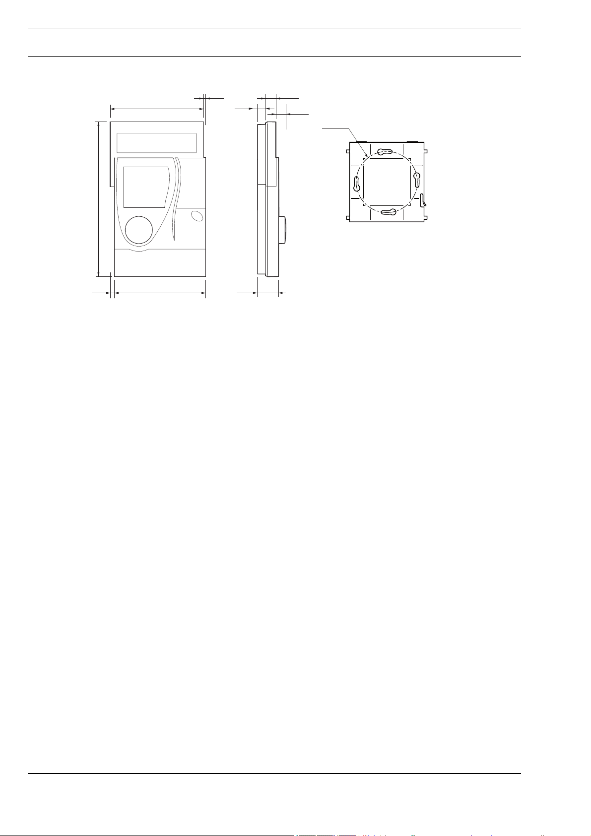
Dimensions WxHxD: 90 x 153.7 x 26.7 mm
Page 3 / 24
A
Page 4
Datasheet 1.10-60.015-01-EN Issue 2016-05-16 ab V2.60
Product DescriptionRBW322-FTL
Dimensions
6.5
3.6
3.5
0.1
0.3
0.4
0.4
R 1.8
0.80.2
A
Page 4 / 24
Page 5
Issue 2016-05-16 ab V2.60
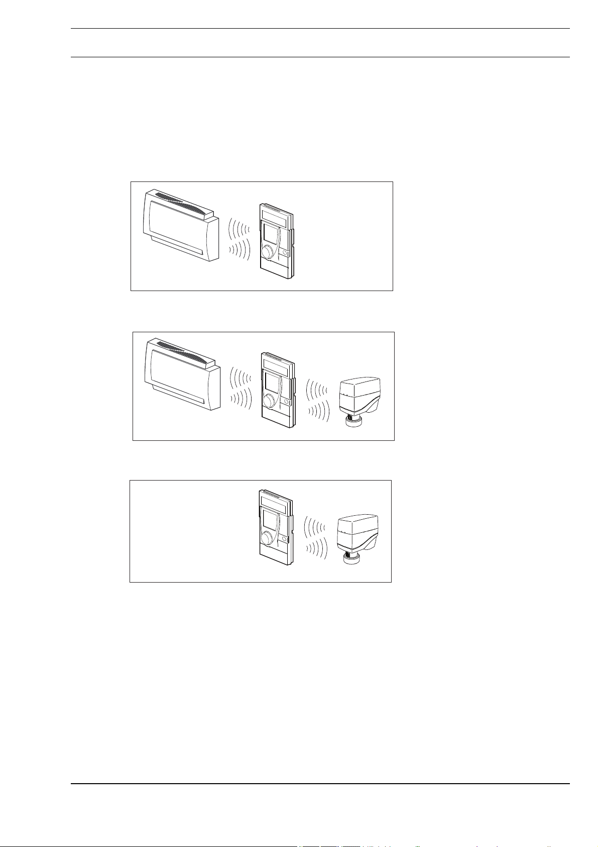
Radio Interface
Communication with the radio partner is cyclical, bidirectional and includes an intelligent synchronization process.
If the radio communication between the RBW322-FTL and the MD15-FTL-xx is interrupted, an
internal resynchronization procedure starts automatically.
Radio connection
- Gateway operation
EnOcean Gateway
Datasheet 1.10-60.015-01-EN
RBW322-FTLProduct Description
RBW322-FTL
- Gateway and pair operation
EnOcean Gateway
-Pair operation
RBW322-FTL MD15-FTL
RBW322-FTL MD15-FTL
Page 5 / 24
A
Page 6
Datasheet 1.10-60.015-01-EN Issue 2016-05-16 ab V2.60
Product DescriptionRBW322-FTL
Installation
NOTICE
!
This product description contains the specific settings and functions of the RBW322-FTL. In addition
to these instructions, the product description of the MD15-FTL-xx must also be observed.
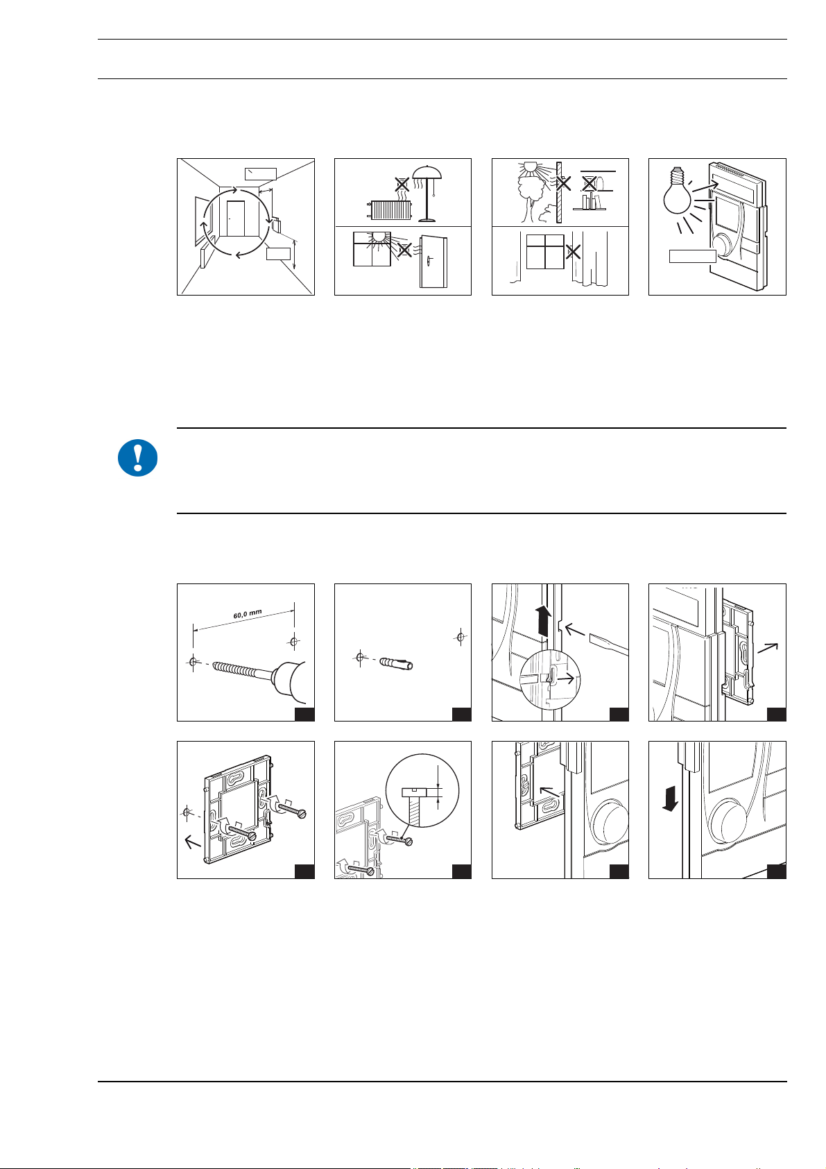
General installation instructions
It is not always possible to freely select the installation location of devices which communicate
wirelessly, as radio data transmission is influenced to a greater or lesser extent by structural or spatial
factors.
Before installation and assembly, the building structure must be analyzed and a series of measurements must be made to determine the specific ranges within the building.
In order to establish operational and reliable communication paths, the following aspects must be
considered before and during planning:
■ Structural factors restrict the transmission ranges which can be reached. Building materials and
screening elements (e.g. suspended ceiling elements, installation shafts, fire doors, etc.) must be
taken into consideration during planning.
!
NOTICE
Elevated humidity increases natural signal damping.
NOTE
Recommendation: Plan radio paths horizontally on a single level with max. 30 m between the
trasmitting and receiving modules.
■ Designed only for use in rooms.
■ Observe minimum distances to potential sources of interference.
- Min. 0.5 m to high-frequency sources of interference (such as microwaves, transformers or
computers)
- Min. 0.5 m to transmitters of other radio systems (such as a cordless telephone or headphones)
- Min. 0.1 m to metal and door frames
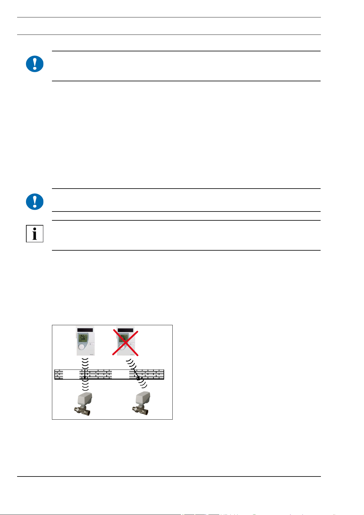
■ Minimize the effect of wall thickness (for example partition walls or room dividers) by ensuring that
the radio signal passes through the walls at as close to a right angle as possible.
12cm >12cm
■ Do not select installation locations in the radio shadow of screening building parts/structures No
direct reception possible.
■ Where the device is installed at the limits of reliability, change the position of the transmitter/
receiver slightly if possible (reduce overlapping effects of radio waves).
A
Page 6 / 24
Page 7
Issue 2016-05-16 ab V2.60
■ The SolarFunk room control modules are to be mounted in a location where they are exposed to
the air circulation in the room so that they can quickly and accurately measure the room
temperature.
Datasheet 1.10-60.015-01-EN
RBW322-FTLProduct Description
= 0,5m
Mounting
!
1,5m
■ As a result of the autonomous operation and wireless installation of RBW322-FTL, the selected
installation location can be changed and optimized at any time without additional effort.
The installation location must have sufficient lighting; using the device in unlit rooms (such as interior
kitchens/bathrooms) shortens the length of the maintenance cycle.
The solar cell is optimized for indoor use and it works particularly efficiently with diffuse lighting.
NOTICE
Prolonged illumination at high intensities, e.g.
- direct sunlight or
- artificial light (such as halogen emitters) can cause damage to the solar cell.
Wall mounting
- Flexible screw mounting
> 150 Lux
Page 7 / 24
1 2 3 4
5
6 7 8
A
Page 8
Datasheet 1.10-60.015-01-EN Issue 2016-05-16 ab V2.60
Product DescriptionRBW322-FTL
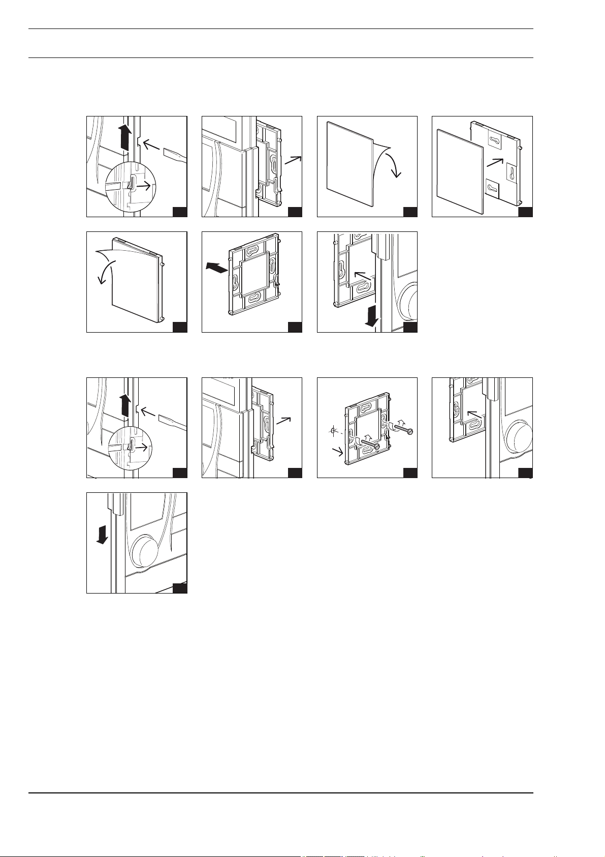
Wall mounting
- Flexible adhesive mounting with double-sided transparent adhesive strips
1 2 3 4
Removal
5 6 7
1 2 3 4
5
A
Page 8 / 24
Page 9

Issue 2016-05-16 ab V2.60
Indicators on the display
11
10
Datasheet 1.10-60.015-01-EN
RBW322-FTLProduct Description
1
2
3
61218240
8
9
7
4
5
6
Item Explanation
1 Time display, temperature or setpoint = Initial display, adjustable (see page 17)
2 Energy storage indicator
The indicator appears when the remaining charge in the energy storage unit of the RBW322-FTL is <
10%.
3 Weekly schedule (current daytime usage times)
4 "Window Open" Recognition indicator
Message is displayed when a rapid temperature drop is detected, or when a radio partner transmits this
message (see page 24).
5 Operating message and malfunction message (see page 22), 12/24 hour display or the
number of the usage time
6 Radio communication indi-
cator
Radio symbol visible
Radio symbol not visible
Radio symbol flashing
7 Automatic mode indicator
Indicator is displayed when automatic mode is active
8 Vacation mode indicator
This icon appears on the display when vacation mode is activated (see page 14).
9 Party mode indicator
This icon appears on the display when party mode is activated (see page 13).
10 Occupancy indicator
11 Summer mode indicator
This icon appears on the display when summer mode is activated.
= Radio communication present, at least one radio partner has been taught-in
= No radio communication present, no radio partners have been taught-in or
all radio partners are malfunctioning
= Radio telegram in transmission/teach-in process
Page 9 / 24
A
Page 10

Datasheet 1.10-60.015-01-EN Issue 2016-05-16 ab V2.60
Product DescriptionRBW322-FTL
Operation, display and settings
The SolarFunk room control module is operated on three levels: the operating level, the configuration
level and the service level.
The descriptions for these can be found on the following pages.
3
1
4
2
Item Designation Explanation
1 Display Displays information regarding the current status
2 Push-and-rotary knob Turn: set value (e.g. setpoint). Turn counterclockwise: reduce
3 Solar cell Generates energy for the room control module
4 Magnetic contact
(below the housing)
5 Occupancy button Occupancy button: Switch between “present” (comfort mode)
6 Programming button Switches to the service level
5
value. Turn clockwise: Increase value.
Press: change levels or confirm display setting.
Switches to the service level
and “absent” (economy mode) or “summer mode”
06
07
7 Service connection
(underside)
NOTE
If the occupancy button is switched to “absent” (economy mode) during an active usage time (see
page 15), the economy mode is active until the next switching point (start time) for “comfort mode”.
A
For authorized service technicians only
Page 10 / 24
Page 11

Issue 2016-05-16 ab V2.60
Comfort mode: Operating mode for a room that is in use (usage status: “Present”). The controller
Economy mode: Energy-saving operating mode (movement status: “Absent”/economy mode) for a
Summer mode: summer operating mode. The temperature is controlled using economy mode
Switching on the device
The device is delivered in storage mode (display switched off).
► This standby state can be ended by simultaneously pressing the push-and-rotary knob and the
occupancy button or occupancy button and programming button for approx. 3 s.
Summer mode
Datasheet 1.10-60.015-01-EN
RBW322-FTLProduct Description
operates with the specified comfort setpoint. This setpoint is set to a comfortable
room temperature.
room that is not in use. The controller operates with a predefined reduced setpoint.
(see page 11).
When the sun icon is displayed, it indicates that the device is operating in summer mode.
The setpoint that has been set for economy mode is activated for the controller.
If summer mode is active, the occupancy display, party mode and the weekly schedule
are inactive.
Summer mode is automatically activated for the time period from 1 June to 31 August or
can be manually switched on or off using the occupancy button.
Pressing the occupancy button for approximately 5 s switches summer mode on or off.
Manually switching between comfort and economy mode
► You can manually switch between comfort mode and economy mode and vice versa by pressing
the “Occupancy button”.
This is displayed by the comfort mode or economy mode icons. The “Auto” icon
also disappears from the display.
NOTE
The manually adjusted operating mode remains active until the next usage time status change.
The weekly schedule with the set usage times becomes active then and the "Auto" symbol is
displayed again.
Page 11 / 24
A
Page 12

Datasheet 1.10-60.015-01-EN Issue 2016-05-16 ab V2.60
Product DescriptionRBW322-FTL
Operating level
The operating level is reached by briefly pressing the knob.
Setting the setpoint
The current setpoint can be adjusted manually using the push-and-rotary knob.
61218240
61218240
► Briefly press the knob.
The setpoint indicator flashes for 2 s.
► Select the desired setpoint using the push-and-rotary knob.
The new selected value flashes for approx. 5 s; it is then automatically confirmed
and the SolarFunk room control module switches to the initial display.
A new setpoint can also be applied by pressing the push-and-rotary knob briefly.
Manuall override will also make the Auto symbol disappear.
NOTE
The manually adjusted setpoint remains active until the next usage time status change.
The sepoints for comfort mode and economy mode, which were set on the configuration level,
become active then (see page 16) and the "Auto" symbol is displayed again.
Configuration level
NOTE
The individual setting functions are exited if no settings are entered within approx. 10 seconds.
The configuration level is reached by pressing the knob for 2 s. The individual setting
functions can then be selected by rotating the knob clockwise, beginning with the party
mode function.
A
Page 12 / 24
Page 13

Issue 2016-05-16 ab V2.60
Setting party mode (usage time extension)
The maximum party time is 8 hours.
This can be set in steps of 30 minutes.
► Press the push-and-rotary knob for 3 s.
► Select the “Party mode” function using the push-and-rotary knob.
► Press the knob briefly; the display flashes.
61218240
Current time = start of party mode (usage time extension).
► Set the end time for party mode (usage time extension) turning the knob.
61218240
The selected comfort mode extension (usage time extension) is shown in the
display by the bar indicator.
► Confirm the entry by briefly pressing the knob.
The display switches back to the initial display.
The comfort mode extension is effective immediately and comfort mode
is switched on.
The activated party mode is indicated by the party icon on the display.
61218240
Party mode can be interrupted by reselecting the "Party mode" function and resetting it
to the current time.
Datasheet 1.10-60.015-01-EN
RBW322-FTLProduct Description
Page 13 / 24
A
Page 14

Datasheet 1.10-60.015-01-EN Issue 2016-05-16 ab V2.60
Product DescriptionRBW322-FTL
Setting vacation mode
► Press the push-and-rotary knob for 3 s.
► Select the “Vacation mode” function using the push-and-rotary knob.
► Press the push-and-rotary knob briefly.
The month display flashes.
Vacation start, vacation end and the setpoint for the vacation time period are set in
sequence:
The day/month to be set flashes on the display.
► Vacation start:
Set the month. Confirm setting by pressing the knob. Set the day. Confirm setting
by pressing the knob.
► Vacation end:
Set the month. Confirm the setting by pressing the knob. Set the day. Confirm the
setting by pressing the knob.
► Set the setpoint for the duration of the vacation. Confirm the setting by pressing
the knob.
The display switches back to the initial display.
Vacation mode begins on the set start date at 00:00 (midnight) and ends on the set end
61218240
NOTE
The vacation time must be at least 2 days, and it does not work retroactively.
If a vacation start is entered which is before the current date, the set dates will not be active until the
next calendar year.
date at 00:00 (midnight).
If a vacation time is set and has not yet begun, the icon is shown on the initial
display.
If vacation mode is active, the vacation end date and the icon are shown on the
display. If vacation mode is active, the weekly schedule is inactive.
Once the set vacation time has elapsed, the vacation mode function is deleted and the
display switches back to the initial display.
Delete or end vacation mode
► Set vacation start equal to vacation end.
Perform settings as described above.
A
Page 14 / 24
Page 15

Issue 2016-05-16 ab V2.60
Setting the weekly schedule
A weekly schedule is available with the following week days:
- MOFR Monday - Friday
61218240
- SASU Saturday - Sunday
- MOSU Monday - Sunday
- Individual days MO, TU, WE, TH, FR, SA and SU
Up to 4 usage times can be set per day.
A usage time consists of a start time and an end time (usage time block).
These can be set of 15 minutes.
► Press the push-and-rotary knob for 2 s.
61218240
► Using the push-and-rotary knob, select the “weekly schedule” function and the desired
week days (for example MOSU).
► Press the knob.
61218240
First usage time/Start time is displayed and flashes, icon is active.
► Turn the push-and-rotary knob to set the start time.
Press the push-and-rotary knob to confirm the setting.
Datasheet 1.10-60.015-01-EN
RBW322-FTLProduct Description
First usage time/End time is displayed and flashes, icon is active.
61218240
► Turn the push-and-rotary knob to set the end time.
Press the push-and-rotary knob to confirm the setting.
1
The display switches to the start time of the second usage time.
Set the second, third and fourth usage times, if desired.
The setting procedure is the same as for the first usage time block.
The display also shows which usage time block (1) is set.
The set utilization times will be saved after 10 s of idle time without further input, when 4
utilization times were entered, or end time = start time.
The usage times of the current day are shown by the bar indicator on the display.
61218240
If a usage time is active, the controller operates in comfort mode. In addition, this
icon is shown on the display.
If the current time is outside of the set usage time blocks, economy mode is active. In
addition, the icon is shown on the display.
Delete usage time:
Warning: Deleting a usage time automatically deletes all subsequent usage times within
the selected weekday span.
Be careful to select the correct weekdays for deletion.
► Select the end time of the usage time block to be deleted as described above.
Page 15 / 24
► Turn the knob left until the end time = start time and then press
the knob.
The corresponding usage time is deleted and no longer displayed.
Default settings: MOSU Monday – Sunday, 6:00 - 20:00 (6 a.m. - 8 p.m.)
A
Page 16

Datasheet 1.10-60.015-01-EN Issue 2016-05-16 ab V2.60
Product DescriptionRBW322-FTL
Setting the setpoints for comfort mode and economy mode
► Press the knob for 3 s.
► Select the “Setpoint” (temperature display) function using the knob.
► Press the knob.
The setpoint for comfort mode flashes and can now be set.
The icon is active.
► Confirm the chosen setpoint for comfort mode by pressing the knob.
► The setpoint for economy mode flashes and can now be set.
The icon is active.
► Confirm the chosen setpoint for economy mode by pressing the knob.
Default setting: Comfort mode setpoint: 22 °C
Economy mode setpoint: 18 °C
Setting the time and date
► Press the knob for 3 s.
► Use the knob to select the “Time + Date” function TIME and press the knob.
The hour, minutes, year, month and day can then be set in sequence.
The values to be set are always flashing.
► Set the time:
Set the hour. Confirm setting by pressing the knob.
Set the minutes. Confirm setting by pressing the knob.
► Set the year:
Confirm setting by pressing the knob.
► Set the month and day:
Set the month. Confirm setting by pressing the knob.
Set the day. Confirm setting by pressing the knob.
Daylight saving time switching occurs automatically according to Central European
standards.
Default setting: Current Central European time
A
Page 16 / 24
Page 17

Issue 2016-05-16 ab V2.60
Setting the time, temperature or setpoint for the initial display
► Press the knob for 3 s.
► Turn the knob to select the “Setting the initial display” function dISP and press the
knob.
► Select the desired initial display using the knob:
- “Initial display: time”
- “Initial display: temperature” or
- “Initial display: setpoint”
Confirm the setting by pressing the knob.
The display switches to the initial display.
Default setting: Initial display temperature
Setting the 12/24 hour display
Datasheet 1.10-60.015-01-EN
RBW322-FTLProduct Description
► Press the knob for 3 s.
► Use the knob to select the “12/24 hour display” function 24h and press the
knob.
► Set 12 or 24 hour display.
Confirm the setting by pressing the push-and-rotary knob.
If the 12 hour display (1) is activated, an additional A for AM or P for PM is shown in the
61218240
Switching the temperature scale °C/°F
display.
Default setting: 24h
1
► Press the knob for 3 s.
► Use the knob to select the “Set the temperature units °C/°F” function TEMP
and press the knob.
► Set the desired temperature units and confirm by pressing the knob.
The display switches to the initial display.
Default setting: °C
Page 17 / 24
A
Page 18

Datasheet 1.10-60.015-01-EN Issue 2016-05-16 ab V2.60
Product DescriptionRBW322-FTL
Service level
To activate the service level, proceed as follows:
■ Using an access code
■ Using a magnet
■ Pressing the set button briefly
Using an access code
► Press the knob for 3 s.
► Use the knob to select the “Service level” function SR.
► Press the knob.
► Enter the 4-digit access code 4321.
Each digit is entered individually and the entry is confirmed by pressing
the push-and-rotary knob.
If the access code was entered incorrectly, the display ER appears.
The room control module changes to the service level.
Using a magnet
► Briefly press the magnet against the upper right-hand side
of the device (see figure).
1
The room control module changes to the service level.
The following functions are available on the service level:
■ Registration Function
■ Delete Function
■ Status display for taught-in radio partners
■ Valve position for service purposes
■ Restore default settings
■ Software version display
► The push-and-rotary knob is used to select the individual functions of the service level.
If you do not take any other actions, the display will return to the initial display after 10 seconds.
Registration Function
See chapter “Teaching in the MD15-FTL-xx wireless partner and EnOcean gateway on
the RBW322-FTL”, page 20.
A
Page 18 / 24
Page 19

Issue 2016-05-16 ab V2.60
Delete Function
Status display for taught-in radio partners
1
1
Datasheet 1.10-60.015-01-EN
RBW322-FTLProduct Description
See chapter "Deleting the wireless partner on the RBW322-FTL", Page 22.
If no radio partners have been taught-in, this status display does not appear.
If radio partners have been taught-in, the following messages are displayed:
■ EnOcean system gateway
EnOcean ID (the last four hexadecimal digits of the system gateway’s EnOcean ID, here
392d), radio status indicator, assigned radio partner (1) 0 (system gateway)
■ Radio actuator
EnOcean ID (the last four hexadecimal digits of the radio actuator’s EnOcean ID, here
C8D6), setpoint (bar indicator, here 50 %), radio status indicator,
assigned radio partner (1) 1 - 4 (radio actuator), if applicable, the Window Open
Detection and battery indicator of the radio partner
► Turning the knob displays these status messages for every taught-in radio partner
in sequence.
Valve Position for Service Purposes
► In the service level, use the knob to select the “Valve position for service purposes”
SERV function.
► Press the knob.
► Turn the knob to select the desired valve position.
Confirm the setting by pressing the knob.
The display switches to the initial display.
Confirming the valve position sends the set valve position to all of the taught-in radio
actuators with the next communication cycle.
Room temperature control is inactive for one transmission/reception interval.
Restore Default Settings
► In the service level, use the knob to select the “Restore default settings”
RES function.
► Press the knob. The display flashes.
► Press the knob again. The “Restore default settings” function is
carried out.
All settings are restored to the default settings, the taught-in radio partners are deleted
and the device switches to its initial state (display is switched off, see page 11).
Page 19 / 24
A
Page 20

Datasheet 1.10-60.015-01-EN Issue 2016-05-16 ab V2.60
Product DescriptionRBW322-FTL
Software version display
► Use the knob to select the “Software version display” function F.
The current software version is displayed.
► Press the push-and-rotary knob briefly.
Displays the software version of internal processor 1.
► Turn push-and-rotary knob.
Displays the software version of internal processor 2.
Teaching in the MD15-FTL-xx wireless partner and EnOcean gateway on the RBW322-FTL
NOTICE
!
This product description contains the specific settings and functions of the RBW322-FTL. In addition
to these instructions, the product descriptions of the MD15-FTL-xx radio partner and EnOcean
gateway must also be observed.
► Select service level (see page 18).
► Use the knob to select the “Teach-in” function T: IN.
■ Teach in wireless actuator
Up to 4 MD15-FTL-xx radio actuators can be taught-in on the RBW322-FTL.
► Use the knob to select the “Teach-in radio small actuator” function ACT.
► Press the knob.
The radio icon flashes.
► A teach-in radio telegram has to be triggered on the MD15-FTL-xx. You can find
details in the documentation of the MD15-FTL-xx.
► If multiple MD15-FTL-xx radio small actuators are to be taught in,
the radio teach-in telegrams must be triggered consecutively.
A
Page 20 / 24
Page 21

Issue 2016-05-16 ab V2.60
NOTE
The “Taught-in radio partners’ status display” function (see page 19) allows you to check which radio
partners are taught-in.
Adding an additional radio actuator is not possible afterwards.
If you want to do this, you must teach in all radio actuators again.
Datasheet 1.10-60.015-01-EN
RBW322-FTLProduct Description
The number of taught-in actuators is displayed approx. 15 s after the last small actuator
was taught in.
If all actuators were synchronized successfully after teach-in, the "Antenna" symbol is
displayed. That can take up to approx. 45 seconds.
Data has been exchanged between the radio partners.
The time between each teach-in may not exceed 15 s.
All wireless actuators must be taught-in within a single teach-in sequence.
If the teach-in process is successful, the radio symbol will be continuously displayed.
Each MD15-FTL-xx radio actuator confirms this visually (status LED lights up for approx.
3 s) and acoustically (beeping tone sounds twice).
!
NOTE
After a successful teach-in process, the device ID of the radio partner is stored in the SolarFunk room
control module. The teach-in process does not need to be performed again when the battery is
changed.
If the teach-in process fails, the radio symbol is not visible on the display.
► The teach-in process must be performed again, or the radio communication path must be
checked. See chapter “General installation instructions”, page 6.
NOTICE
If multiple radio partners are being taught-in, you must check during the teach-in process that each
radio partner acknowledges the successful teach-in process visually (illumination of the status LED
for approx. 3 s) and acoustically (2 signal tones in succession).
If this does not occur for one of the radio partners, the entire teach-in process must be repeated.
■ Teaching in on an EnOcean system gateway
► Use the knob to select the “Teach-in system gateway” function GATE.
Page 21 / 24
► Press the knob.
The radio icon flashes.
A teach in radiogram is sent to the system gateway and a teach-in response is awaited.
You can find details in the documentation of the EnOcean system gateway.
If the teach-in process is successful, the radio symbol will be continuously displayed.
A
Page 22

Datasheet 1.10-60.015-01-EN Issue 2016-05-16 ab V2.60
Product DescriptionRBW322-FTL
Deleting the wireless partner on the RBW322-FTL
► Use the knob to select the “Delete” function dEL in the service level.
► Press the knob until the radio icon on the display disappears (approx. 3 s).
All taught-in radio partners are deleted.
Operating and Malfunction Messages
Icon on display
Explanation
Wireless communication with at least one taught-in MD15-FTL-xx wireless partner has been interrupted for more than one hour.
If no signal is received from the MD15-FTL-xx for an extended period of time,
the display switches to .
This warning disappears once the communication to the missing wireless partner is re-established.
If the wireless communication to all taught-in wireless partners is interrupted,
the wireless icon is no longer displayed.
Wireless communication with at least one taught-in MD15-FTL-xx wireless partner has been interrupted for more than four hours and a resynchronization has
failed.
This warning disappears once the communication to the missing wireless partner is re-established.
If the wireless communication to all taught-in wireless partners is interrupted,
the wireless icon is no longer displayed.
Room control module system time is faulty.
Wireless communication to the taught-in EnOcean system gateway is interrupted.
The battery capacity of at least one MD15-FTL-xx is too low (<10%).
The batteries of the wireless small actuator must be replaced.
If no signal is received from the MD15-FTL-xx for an extended period of time,
the display switches to .
Room control module transmission function faulty, supersedes all other messages.
NOTE
If the malfunction message appears, the batteries of the MD15-FTL-xx must be changed or the
radio communication path must be checked. See chapter “General installation instructions”, page 6.
NOTE
Operating and malfunction messages have priority over the 12/24 hour display.
A
Page 22 / 24
Page 23

Issue 2016-05-16 ab V2.60
Transmission function malfunctioning
The radio connection is continuously monitored. The “Δ8” icon appears on the display if a transmission function malfunction is detected in the RBW322-FTL.
The following troubleshooting procedures can be implemented:
► Reset RBW322.FTL to factory settings (see p.19).
► Register the radio partner again.
The RBW322-FTL has a serious malfunction if the “Δ8” icon continues to appear. It should be
checked by an authorized service technician.
System time
The RBW322-FTL's internal system time is monitored constantly. The “Δ3” icon appears on the
display if a system time malfunction is detected in the RBW322-FTL.
► Reset the time (see page 16).
The RBW322-FTL has a serious malfunction if the “Δ3” icon continues to appear. It should be
checked by an authorized service technician.
Datasheet 1.10-60.015-01-EN
RBW322-FTLProduct Description
The “Δ8” icon disappears from the display.
The “Δ3” icon disappears from the display.
Page 23 / 24
A
Page 24

Datasheet 1.10-60.015-01-EN Issue 2016-05-16 ab V2.60
Product DescriptionRBW322-FTL
Plant
Further information on using the EnOcean wireless standard EEP D2-10-01
Custom Warnings
The RBW322-FTL does not display sent warnings via the bits “Custom Warning 1” and “Custom
Warning 2”.
Window Open Detection
The RBW322-FTL does not have an open window detection function. It only uses the information
from the radio messages from taught-in actuators or from a connected gateway.
Means that rapid temperature drop was triggered, e. g. by opening a window.
Room Control Mode
The RBW322-FTL supports the “Comfort”, “Economy” and “Building Protection” control modes.
“Pre-Comfort” is not assigned to an assignment program.
Menu locks and Display Switch-Off
Menu lock and display switch-off commands are overridden if the radio connection to the gateway is
interrupted.
Switching Between Daylight Savings/Standard Time
The RBW322-FTL automatically switches between daylight savings and standard time. It follows the
calendar for central Europe.
This function can be activated or deactivated via the “Daylight Savings Time Flag” bit.
When activating/deactivating this function, the RBW322-FTL does not automatically detect whether
the time should be adjusted straight away or not. The time should be synchronized immediately after
making this kind of changes.
Date and Time Setting
If the defined validity ranges are exceeded, the dates and times transmitted by the gateway are
rounded up or down to the valid ranges.
The year can be set to a minimum of 2014.
Weekly Schedule Transmission and Setting:
The weekly schedule is transmitted via utilization time blocks (connected time period assigned with
usage status or comfort mode) that are characterized by their start and stop time.
The RBW322-FTL processes and saves the weekly schedule in 15 minute blocks. The utilization time
periods should also be transmitted in whole quarters of an hour to prevent deviations between the set
and copied weekly schedule.
A maximum of four utilization time blocks are permitted per weekday or weekday range. If more utilization time blocks are transmitted, the RBW322-FTL uses the first four of each and discards the rest.
An increased radio load may occur due to the possible connection of weekly schedule messages
(several telegrams that belong together). Unnecessary weekly schedule transmissions should,
therefore, be avoided.
A
Page 24 / 24
 Loading...