

Page 1
Kieback&Peter GmbH & Co. KG
Tempelhofer Weg 50, 12347 Berlin/Germany
Telefon: +49 30 60095-0, Telefax: +49 30 60095-164
www.kieback-peter.de, info@kieback-peter.com
Datasheet 1.10-60.010-01-EN
RBW301-C, RBW302-C, RBW304-C, RBW305-C
Issue 2017-07-20
A
Änderungen vorbehalten - Contents subject to change - Sous réserve de modifications - Reservado el derecho a modificación - Wijzigingen
voorbehouden - Con riserva di modifiche - Innehåll som skall ändras - Změny vyhrazeny - Zmiany zastrzeżone - Возможны изменения A változtatások jogát fenntartjuk - ؍⮉ᵚ㓿䙊⸕㘼᭩ࣘⲴᵳ࣋
Product Description
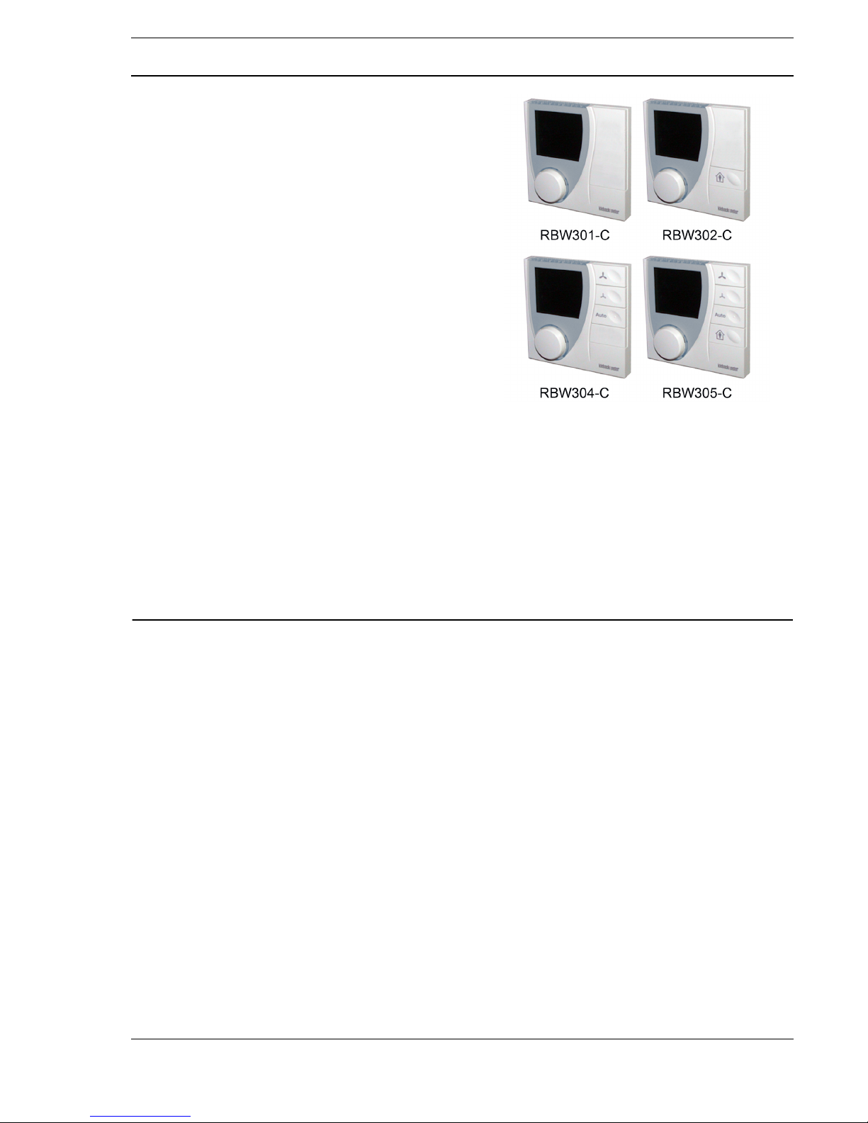
RBW301-C, RBW302-C, RBW304-C, RBW305-C
Room Control Module
Application
Room control module with display, room temperature
sensor and manual setting of the room temperature
setpoint for the following room controllers and
automation systems:
■ RCN150-L, RCN151-L, RCN152-L, RCN155-L
■ RCC200-L or RCN200-L
■ RCN420-B
■ DDC4000, DDC420
Different variants with a graded range of functions are
available: Set room temperature, manual and automatic
fan control, presence button (present/absent).
Content Page
Important Information Regarding Product Safety ..................................................................................................2
Item........................................................................................................................................................................3
Technical Data.....................................................................................................................................................3
Accessories (not included in delivery) .................................................................................................................3
Compatibility ........................................................................................................................................................4
Dimensions..........................................................................................................................................................4
Connection...........................................................................................................................................................5
Mounting ................................................................................................................................................................6
Function/Operation ................................................................................................................................................8
Setting the room temperature..............................................................................................................................9
Energy saving function (RBW304-x, RBW305-x) ................................................................................................9
Schedule..............................................................................................................................................................9
CAN Address Setting...........................................................................................................................................10
Installation............................................................................................................................................................11
Notes for service technicians...............................................................................................................................11
Page 2
A
Page 2 / 12
Product DescriptionRBW301-C, RBW302-C, RBW304-C, RBW305-C
Datasheet 1.10-60.010-01-EN Issue 2017-07-20
Important Information Regarding Product Safety
Safety Instructions
This data sheet contains information on installing and commissioning the product "RBW301-C,
RBW302-C, RBW304-C, RBW305-C". Each person who carries out work on this product must have
read and understood this data sheet. If you have any questions that are not resolved by this data
sheet, you can obtain further information from the supplier or manufacturer.
If the product is not used in accordance with this data sheet, the protection provided will be impaired.
Applicable regulations must be observed when installing and using the device. Within the EU, these
include regulations regarding occupational safety and accident prevention as well as those from the
VDE (Association for Electrical, Electronic & Information Technologies). If the device is used in other
countries, it is the responsibility of the system installer or operator to comply with local regulations.
Mounting, installation and commissioning work on the devices may only be carried out by qualified
technicians. Qualified technicians are persons who are familiar with the described product and who
can assess given tasks and recognize possible dangers due to technical training, knowledge and
experience as well as knowledge of the appropriate regulations.
Legend
WARNING
Indicates a hazard of medium risk which can result in death or severe bodily injury if it is not avoided.
CAUTION
Indicates a hazard of low risk which can result in minor or medium bodily injury if it is not avoided.
!
CAUTION
Indicates a hazard of medium risk which can result in material damage or malfunctions if it is not
avoided.
NOTE
Indicates additional information that can simplify the work with the product for you.
Notes on Disposal
For disposal, the product is considered waste from electrical and electronic equipment (electronic
waste) and must not be disposed of as household waste. Special treatment for specific components
may be legally binding or ecologically sensible. The local and currently applicable legislation must be
observed.
Page 3
A
Page 3 / 12
Datasheet 1.10-60.010-01-EN
RBW301-C, RBW302-C, RBW304-C, RBW305-CProduct Description
Issue 2017-07-20
Item
Technical Data
Accessories (not included in delivery)
RBW301-C Room control module with room temperature sensor and display, settings made
using knob and confirmation key (room temperature setpoint, timer functions)
RBW302-C All features of RBW301-C plus presence button
RBW304-C All features of RBW301-C plus buttons for fan control
RBW305-C All features of RBW301-C plus buttons for fan control, presence button
Nominal voltage DC 12 V, ± 10%, 0.96 W
Power consumption 0.6 W backlighting (OFF)
0.96 W backlighting (ON)
Measured value Room temperature of spaces in homes or commercial premises
Measuring system Integrated digital sensor
Display and
controls
■ Backlit display: Feedback, presence, fan status, heating/cooling,
window contact, weekly schedule, time, date, project-specific
messages, service level
■ Knob with confirmation key for setting the temperature, time and weekly
schedule; display of service data
Keys:
Fan control level increasing: Fan on, increased speed
Fan control level decreasing: Decreased speed, fan off
Fan in automatic mode (fan speed specified by controller)
Presence button: Switch to present or absent
Interfaces 4-wire terminal or RJ9 jack
Measuring range 0 °C to 50 °C
Relative measuring accu-
racy
0.1 K
Housing Plastic housing, RAL 9010 (pure white)
Other colors on request
Protection class III
Degree of protection IP30
Ambient temperature 0 °C to 50 °C
Ambient humidity During operation: 20% to 80% r.h.; non-condensing
Out of operation: 5% to 90% r.h.; non-condensing
Installation Screw mounting on standard flush-mounted box
Weight 0.12 kg
Dimensions WxHxD mm 90 x 90 x 32,5;
Depth in wall 9.5
Z146 Adapter frame for direct wall mounting
Page 4
A
Page 4 / 12
Product DescriptionRBW301-C, RBW302-C, RBW304-C, RBW305-C
Datasheet 1.10-60.010-01-EN Issue 2017-07-20
Compatibility
Can be connected to:
■ RCN150-L, RCN151-L, RCN152-L, RCN155-L, RCC200-L, RCN200-L or RCN420-B room
controllers
up to four room control modules depending on the application
■ DDC420 automation station
up to 3 room control modules
■ DDC4200-L, DDC4200, DDC4002, DDC4400, DDC4200e, DDC4002e or DDC4400e automation
stations
depending on the fieldbus, up to nine room control modules to addresses 1 to 9
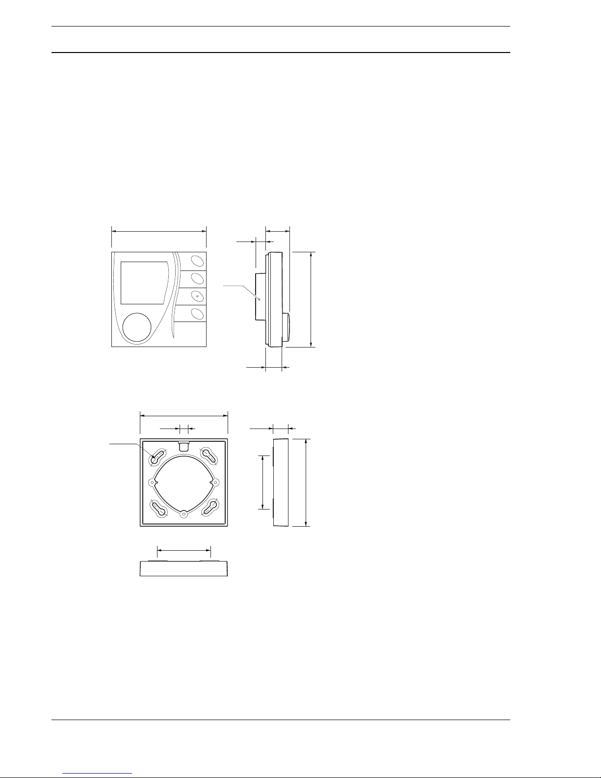
Dimensions
- Z146
90.0 23,0
16,0
90,0
9,5
Ø 50
83,0
83,0
8,4
R 35,0
49,5
49,5
14,0
Page 5

A
Page 5 / 12
Datasheet 1.10-60.010-01-EN
RBW301-C, RBW302-C, RBW304-C, RBW305-CProduct Description
Issue 2017-07-20
Connection
Sample connection
- RCC200-L
+12V=
C
–
RJ
0V
C+
17 18 19 20
RBW20X-C
RBW30X-C
DDC420
21
2019
22
+
-
0V
12VDC
CAN -
CAN +
0V DC
+12V DC
19
1817
20
RBW20X-C
RBW30X-C
RCN420-B
21
2019
22
+
-
0V
12VDC
CAN -
CAN +
0V DC
+12V DC
19
1817
20
52 5350 51
98
7
16
15
1032
1
6
5
4
57
60
59
58
GND
K1
P1
GNDK3GND
P3
GND
K2
P2
13121114
GNDK4GNDP4GND
P5
+12V=0VC
+Cí
AB
LON
LN
L L N N
AB
K6K5 K7
42 4340 4137 38
K8
:
18
17
GND
P6
20
19
GND
P7
22
21
GND
P8
24
23
GND
K9
26
25
GND
K10
NL
17 18 19 20
17 18 19 20
+12V=0VC
+
C
í
17 18 19 20
RJ
17 18 19 20
17 18 19 20
17 18 19 20
RJ
RJ
230V~
230V~
230V~
230V~
24V=
$$
Page 6

A
Page 6 / 12
Product DescriptionRBW301-C, RBW302-C, RBW304-C, RBW305-C
Datasheet 1.10-60.010-01-EN Issue 2017-07-20
Mounting
!
CAUTION
Installation and removal may only be carried out by qualified technicians when the power is switched
off.
Choose an installation location that is subject to the air flow of the room to ensure that the room
controller can quickly and accurately measure the room temperature.
Installation on a standard flush-mounted box (RJ9 connector)
1,5m
= 0,5m
≤ 2,5
1 2
Z178
3 4
5 6
Page 7

A
Page 7 / 12
Datasheet 1.10-60.010-01-EN
RBW301-C, RBW302-C, RBW304-C, RBW305-CProduct Description
Issue 2017-07-20
Mounting on standard flush-mounted box (4-wire on terminal)
Direct wall mounting with Z146 adapter frame (4-wire on terminal)
1 2 3 4
5 6
Z146
1
49,5 mm
2 3
RJ9
4
RJ9
3 mm
5 6 7 8
9 10
11
Page 8

A
Page 8 / 12
Product DescriptionRBW301-C, RBW302-C, RBW304-C, RBW305-C
Datasheet 1.10-60.010-01-EN Issue 2017-07-20
Function/Operation
Display symbols
1 [Knob]
+
[confirmation key]
Rotate: Set the value (e.g. temperature). Left: Reduce. Right:
Increase.
Press: Confirm display setting
2 Presence button (power save button): Switch between “Present” and
“Absent” (RBW302-x, RBW305-x)
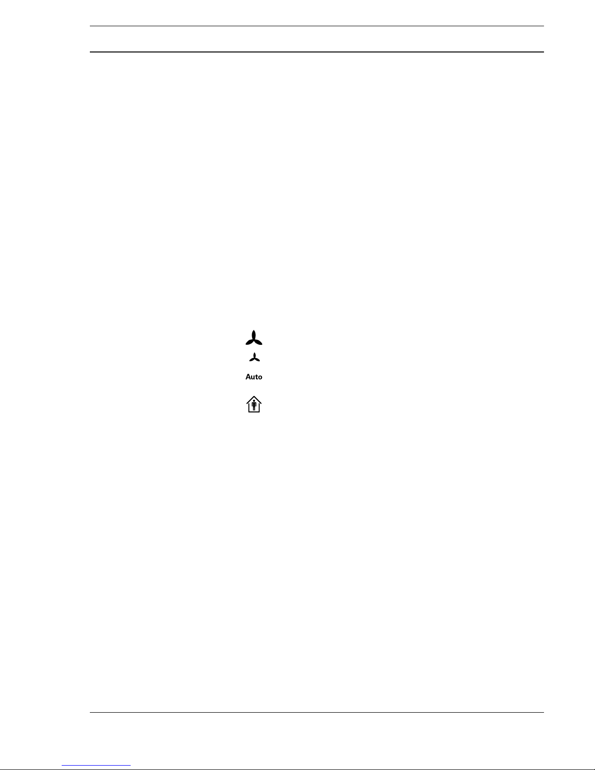
3 Fan in automatic mode: Fan speed specified by the controller
(RBW304-x, RBW305-x)
4 Reduce speed, fan off
(RBW304-x, RBW305-x)
5 Fan on, increase speed
(RBW304-x, RBW305-x)
6 Backlit display
“Present”: Settings can be made.
Additionally: Display of the switch-on time for the utilization schedule
(timer and ).
“Absent”: No settings can be made.
Additionally: Display of the switch-off time for the utilization schedule
(timer and ).
Fan in automatic operating mode. The fan levels vary and the fan may also be
switched off completely at times.
Fan is switched off Fan can be switched to three dif-
ferent levels.
Level 1:
Low, Level 2: Medium, Level 3:
High
Symbol: Heating
Flashing symbol:
Fast heating
Symbol: Cooling
Flashing symbol:
Fast cooling
Temperature display Time display
When window contacts are connected and as soon as a window is opened: No
cooling or heating occurs. The temperature cannot be changed.
Utilization times setting on the corresponding day.
Example: Two utilization times are set for the day, from 5 a.m. to 1 p.m. and from
5 p.m. to 8 p.m.
1
2
3
4
5
6
Page 9

A
Page 9 / 12
Datasheet 1.10-60.010-01-EN
RBW301-C, RBW302-C, RBW304-C, RBW305-CProduct Description
Issue 2017-07-20
Setting the room temperature
Requirements: Indicator on the display:
► Rotate or press the knob.
The temperature value is displayed and flashes.
► Rotate right: Increase the temperature. Rotate left: Reduce the temperature.
The temperature can be set over a range of up to +/-9.9 degrees.
► Press the knob: The preset temperature is saved and displayed.
The temperature is regulated accordingly.
Energy saving function (RBW304-x, RBW305-x)
► Switch the presence button to “Absent” when you leave the room for a longer period of time.
Indicator on the display:
The energy saving function is activated and the temperature is set to a preconfigured value
(can be displayed, but not adjusted).
► Switch the presence button to “Present” when you return to the room.
Indicator on the display:
The energy saving function is switched off. The temperature is regulated accordingly.
Schedule
(Supported by RCC200-L, RCN200-L and DDC420)
Setting the timer
The following schedules (two timers in each case) are available: MO FR (working days), SA SU
(weekend), MO SU (week) as well as MO TU WE TH FR SA SU for the individual days.
► Press and hold the knob for three seconds.
The schedules are displayed.
► Rotate the knob: Select the schedule. Press the knob: Confirm selection.
First timer: The start time is displayed and flashes. Indicator on the display: , time, .
► Rotate the knob: Set the start time. Press the knob: Confirm the setting.
First timer: The end time is displayed and flashes. Indicator on the display: , time, .
► Rotate the knob: Set the end time. Press the knob: Confirm the setting.
The display switches to the start time of the second timer.
Second timer: If required, set in the same way as for the first timer and confirm. Indicator on
the display: , time,
The timer settings are shown on the display on the corresponding day of the week.
Deleting the second timer
► Select the timer end time as described above. Indicator on the display: , time,
► Rotate the knob to the left (end time = start time). Press the knob: Confirm the setting.
Timer is deleted and is no longer displayed.
Deleting the first and second timers
► Select the end time of the first timer as described above. Indicator on the display: , time,
► Rotate the knob to the left (end time = start time). Press the knob: Confirm the setting.
The first and second timer have been deleted and are no longer displayed.
Page 10

A
Page 10 / 12
Product DescriptionRBW301-C, RBW302-C, RBW304-C, RBW305-C
Datasheet 1.10-60.010-01-EN Issue 2017-07-20
Temporarily extending the room utilization time (RBW302-x, RBW305-x)
Requirement: The timer is set but is not active (outside of room utilization time).
► Switch the presence button to “Present”.
The utilization time extension is displayed as a timer.
► Rotate the knob: The utilization time can be extended by up to four hours (from the set time).
The new utilization time extension is displayed as a timer.
Setting the time
► Press and hold the knob for three seconds.
► Rotate the knob: Select the TIME function. Press the knob: Confirm selection.
► Set the time:
Set the hour. Confirm the setting.
Set the minute. Confirm the setting.
► Set the date:
Set the year. Confirm the setting.
Set the month. Confirm the setting.
Set the day. Confirm the setting.
The settings for the time and date are applied. The display changes back to the standby
display.
CAN Address Setting
The address switch (1) is located on the PCB of the room control module (rear of device).
Address setting:
■ For RCN150-L, RCN151-L, RCN152-L, RCN155-L, RCC200-L or RCN200-L with basic appli-
cation: Address 1 for main room,
Address 2 for secondary room
■ For RCN150-L, RCN151-L, RCN152-L, RCN155-L, RCC200-L, RCN200-L or RCN420-B
configured with PS4000: Address 1 to 4 for room 1 to 4
■ DDC4000: Address 1 to 9
■ DDC420: Address 1 to 9
1 Adressschalter
1
Page 11

A
Page 11 / 12
Datasheet 1.10-60.010-01-EN
RBW301-C, RBW302-C, RBW304-C, RBW305-CProduct Description
Issue 2017-07-20
Installation
■ Online installation with the RCxxxx-L technolon® room controller:
The RCxxxx-L technolon® room controller can also be identified directly on the room control
module using a magnet (3). To do so, guide a magnet (3) along the right side of the RBW30x-C
room control module.
This triggers the service PIN in the RCxxxx-L room controller internally. This is indicated by a
service LED (4) on the top part of the housing on the room control modules that lights up green.
Notes for service technicians
Additional indicators on the display
Querying the service settings
► Press and hold the knob for three seconds.
► Rotate the knob: Select the SR function. Press the knob: Confirm selection.
► PIN entry:
In order to get to the service level, enter the corresponding code of 2460. Confirm the code
numbers individually.
► Query of the valve outputs:
You can query the service values with this function (the associated symbols are shown on the
display).
RBW305-C
3
4
Setting the heating and cooling valve (0% to 100%)
Triangle with a number between 0 and 9: Error code that needs to be rectified by the
service technician. The displayed error messages are project-specific.
Display of the version number (example)
Page 12

A
Page 12 / 12
Product DescriptionRBW301-C, RBW302-C, RBW304-C, RBW305-C
Datasheet 1.10-60.010-01-EN Issue 2017-07-20
 Loading...