

Page 1
Issue 2018-02-05
Datasheet 1.10-51.012-01-EN
Product Description
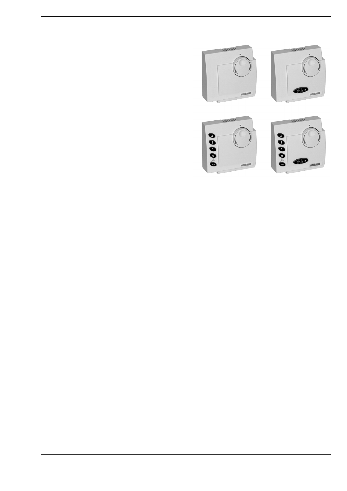
Room Control Modules RBW101, RBW103,
RBW106, RBW108
Application
Room control modules with room temperature sensors
and manual setting of the room temperature setpoint for
use with a technolon® room controller. A room control
module can be connected to each technolon® room
controller. The technolon® room controller can be
identified on the LON network quickly and easily by
entering the service PIN directly on the room control
module.
To be used only with technolon® room controllers
RCN092-L to RCN142-L.
The RBW103 room control module also includes
operating buttons for switching the occupancy between
“present” and “absent.”
The RBW106 room control module also includes
operating buttons for switching between three fan levels
as well as a button for automatic mode.
Like the RBW103, the RBW108 room control module also
includes operating buttons for switching between three
fan levels as well as a button for automatic mode.
RBW101, RBW103, RBW106, RBW108
RBW101
RBW106
RBW103
RBW108
Content Page
Important Information Regarding Product Safety ..................................................................................................2
Item........................................................................................................................................................................3
Technical Data.....................................................................................................................................................3
Accessories (not included in delivery) .................................................................................................................3
Dimensions..........................................................................................................................................................4
Connection...........................................................................................................................................................4
Mounting ................................................................................................................................................................4
Network installation................................................................................................................................................6
Änderungen vorbehalten - Contents subject to change - Sous réserve de modifications - Reservado el derecho a modificación - Wijzigingen
voorbehouden - Con riserva di modifiche - Innehåll som skall ändras - Změny vyhrazeny - Zmiany zastrzeżone - Возможны изменения A változtatások jogát fenntartjuk - ؍⮉ᵚ㓿䙊⸕㘼᭩ࣘⲴᵳ࣋
Kieback&Peter GmbH & Co. KG
Tempelhofer Weg 50, 12347 Berlin/Germany
Telefon: +49 30 60095-0, Telefax: +49 30 60095-164
www.kieback-peter.de, info@kieback-peter.com
A
Page 2

Datasheet 1.10-51.012-01-EN Issue 2018-02-05
Product DescriptionRBW101, RBW103, RBW106, RBW108
Important Information Regarding Product Safety
Safety Instructions
This data sheet contains information on installing and commissioning the product "RBW101,
RBW103, RBW106, RBW108". Each person who carries out work on this product must have read
and understood this data sheet. If you have any questions that are not resolved by this data sheet,
you can obtain further information from the supplier or manufacturer.
If the product is not used in accordance with this data sheet, the protection provided will be impaired.
Applicable regulations must be observed when installing and using the device. Within the EU, these
include regulations regarding occupational safety and accident prevention as well as those from the
VDE (Association for Electrical, Electronic & Information Technologies). If the device is used in other
countries, it is the responsibility of the system installer or operator to comply with local regulations.
Mounting, installation and commissioning work on the devices may only be carried out by qualified
technicians. Qualified technicians are persons who are familiar with the described product and who
can assess given tasks and recognize possible dangers due to technical training, knowledge and
experience as well as knowledge of the appropriate regulations.
Legend
WARNING
Indicates a hazard of medium risk which can result in death or severe bodily injury if it is not avoided.
!
CAUTION
Indicates a hazard of low risk which can result in minor or medium bodily injury if it is not avoided.
CAUTION
Indicates a hazard of medium risk which can result in material damage or malfunctions if it is not
avoided.
NOTE
Indicates additional information that can simplify the work with the product for you.
Notes on Disposal
For disposal, the product is considered waste from electrical and electronic equipment (electronic
waste) and must not be disposed of as household waste. Special treatment for specific components
may be legally binding or ecologically sensible. The local and currently applicable legislation must be
observed.
A
Page 2 / 6
Page 3

Issue 2018-02-05
Item
RBW101 Room control module with room temperature sensor and manual setting of the
RBW103 Room control module with room temperature sensor and manual setting of the
RBW106 Room control module with room temperature sensor and manual setting of the
RBW108 Room control module with room temperature sensor and manual setting of the
Technical Data
Nominal voltage DC 5 V ± 20%, 25 mA
Measured value Room temperature of spaces in homes or offices
Measuring systems Integrated digital room sensor
Setpoint adjuster Digital, setting knob with trend arrows
Measuring range 0 °C to 45 °C
Operating buttons Back-lit
Datasheet 1.10-51.012-01-EN
RBW101, RBW103, RBW106, RBW108Product Description
room temperature setpoint.
room temperature setpoint, with operating buttons for switching between “present” and “absent.”
room temperature setpoint, with operating buttons for switching between three fan
levels as well as a button for automatic mode.
room temperature setpoint, with operating buttons for switching between “present”
and “absent,” buttons for switching between three fan levels as well as a button for
automatic mode.
RBW103 Button to set occupancy to “present”
RBW106 Buttons to switch between fan levels (off, level
RBW108 Button to set occupancy to “present”
Ambient temperature0 °C to 45 °C
Ambient humidity Non-condensing
Installation Mounted on wall or on flush-mounted box
Interface
for room control
module
Degree of protection IP30
Dimensions WxHxD mm 82.5 x 82.5 x 30
Weight 0.11 kg
Accessories (not included in delivery)
Z178 Connection line: room control module <> room controller (RJ plug on both sides, 10 m)
Z178/2 Adapter: RJ plug - terminal block, 4-pole (15 cm)
Z178-15M Connection line: room control module <> room controller (RJ plug on both sides, 15 m)
Z178-CIAT VConnection line: room control module <> room controller (RJ plug on both sides, 1,5 m)
4-wire or RJ9 socket, for connecting to a technolon® RCNxxx-L room controller, max. cable length 20 m
Button to set occupancy to “absent”
1, level 2, level 3 and automatic mode)
Button to set occupancy to “absent”
Buttons to switch between fan levels (off, level
1, level 2, level 3 and automatic mode)
Page 3 / 6
A
Page 4

Datasheet 1.10-51.012-01-EN Issue 2018-02-05
Product DescriptionRBW101, RBW103, RBW106, RBW108
Dimensions
82,5 30,0
82,5
Connection
RBW10x
Mounting
Tx
Rx
5V=
12
WARNING
Contact with live parts of electrical domestic installation can cause death due to electric shock.
Mounting/removal may only be carried out when power is switched off.
The room control module can be mounted on the wall or onto a flush-mounted box.
Choose an installation location that is subject to the air flow of the room to ensure that the room
controller can quickly and accurately measure the room temperature.
34
0V=
5
= 0,5m
RJ
1,5m
CAUTION
!
Lines for the power supply and Rx/Tx are to be laid together in one shielded cable that is a maximum
of 20 m, cable type at least 0.8 mm in diameter, with the wires twisted together in pairs.
A
Page 4 / 6
Page 5

Issue 2018-02-05
Datasheet 1.10-51.012-01-EN
RBW101, RBW103, RBW106, RBW108Product Description
- RJ9 socket (connection with pre-assembled cable)
Z178
1 2 3
5 6
4-wire (connection to terminals)
1 2 3 4
4
Page 5 / 6
5 6
A
Page 6

Datasheet 1.10-51.012-01-EN Issue 2018-02-05
4
Product DescriptionRBW101, RBW103, RBW106, RBW108
Network installation
Network installation is performed using a network management tool based on LonWorks LNS3
network services.
Offline installation
The neuron ID of the technolon® room controller can be found on the included pull-off bar code label,
which is used for system documentation.
A simple bar code reader can be used for reading in the neuron ID.
Online installation
■ Online installation on the technolon® room controller RCNxxx-L:
The node is identified by manually inputting the neuron ID code or by activating the service PIN (1)
on the technolon® room controller RCNxxx-L.
(1) Operating voltage and service LED
(2) Status LED
1
2
■ Online installation on the RBW10x room control module:
The RCNxxx-L technolon® room controller can also be identified quickly and easily directly on the
RBW10x room control module using a magnet (5). To do so, guide a magnet (5) along the right side
of the RBW10x room control module.
Internally, this triggers the service PIN in the RCN room controller. This is indicated when the service
LED (4) on the top part of the RBW10x housing lights up green.
3
5
(3) Service PIN
RBW108
A
Page 6 / 6
 Loading...