

Page 1

Issue 2014-09-04
Datasheet 3.09-20.150-01-EN
Product Description
MD15/230 Small Actuator
with RZ/RWZ15..25 two-way/three-way valves
Application
The MD15/230 small actuator for 3-point control systems for
zone post-treatment devices for heating, ventilation and air
conditioning systems.
Positive connection with automatic coupling.
MD15/230
Content Page
Important Information Regarding Product Safety ..................................................................................................2
Item........................................................................................................................................................................3
Technical Data.....................................................................................................................................................3
Dimensions..........................................................................................................................................................4
Connection...........................................................................................................................................................4
RZ15..25 two-way valves and RWZ15..25 three-way valves with MD15/230 small actuator ................................5
Types...................................................................................................................................................................5
Accessories .........................................................................................................................................................6
Technical Data: RZ/RWZ15..25 valves................................................................................................................7
Valve Installation....................................................................................................................................................9
Installation and Commissioning of the Small Actuator.........................................................................................10
Removal of the Small Actuator ............................................................................................................................11
Manual adjustment ..............................................................................................................................................12
Änderungen vorbehalten - Contents subject to change - Sous réserve de modifications - Reservado el derecho a modificación - Wijzigingen
voorbehouden - Con riserva di modifiche - Innehåll som skall ändras - Změny vyhrazeny - Zmiany zastrzeżone - Возможны изменения -
A változtatások jogát fenntartjuk - ֱ⬭㒣䗮ⶹ㗠ᬍࡼⱘᴗ
Kieback&Peter GmbH & Co. KG
Tempelhofer Weg 50, 12347 Berlin/Germany
Telefon: +49 30 60095-0, Telefax: +49 30 60095-164
www.kieback-peter.de, info@kieback-peter.com
A
Page 2
Datasheet 3.09-20.150-01-EN Issue 2014-09-04
Product DescriptionMD15/230
Important Information Regarding Product Safety
Safety Instructions
This data sheet contains information on installing and commissioning the product "MD15/230". Each
person who carries out work on this product must have read and understood this data sheet. If you
have any questions that are not resolved by this data sheet, you can obtain further information from
the supplier or manufacturer.
If the product is not used in accordance with this data sheet, the protection provided will be impaired.
Applicable regulations must be observed when installing and using the device. Within the EU, these
include regulations regarding occupational safety and accident prevention as well as those from the
VDE (Association for Electrical, Electronic & Information Technologies). If the device is used in other
countries, it is the responsibility of the system installer or operator to comply with local regulations.
Mounting, installation and commissioning work on the devices may only be carried out by qualified
technicians. Qualified technicians are persons who are familiar with the described product and who
can assess given tasks and recognize possible dangers due to technical training, knowledge and
experience as well as knowledge of the appropriate regulations.
Legend
WARNING
Indicates a hazard of medium risk which can result in death or severe bodily injury if it is not avoided.
!
CAUTION
Indicates a hazard of low risk which can result in minor or medium bodily injury if it is not avoided.
NOTICE
Indicates a hazard of medium risk which can result in material damage or malfunctions if it is not
avoided.
NOTE
Indicates additional information that can simplify the work with the product for you.
Notes on Disposal
For disposal, the product is considered waste from electrical and electronic equipment (electronic
waste) and must not be disposed of as household waste. Special treatment for specific components
may be legally binding or ecologically sensible. The local and currently applicable legislation must be
observed.
A
Page 2 / 12
Page 3

Issue 2014-09-04
Item
MD15/230 Small actuator
Technical Data
Nominal voltage AC 230 V ±10 %; 50/60 Hz; 2.5 VA
Control 3-point signal (Open/Stop/Closed)
Connection Built-in cable: 1.5 m, 3 x 0.34 mm
Motor switch-off Actuator spindle: running out = load-dependant, running in = load-depen-
Display LED display for operating voltage and status
Actuating noise <31 dB
Actuating stroke Max. 9 mm
Positioning time 15 s/mm
Thrust 150 N
Position indication Stroke range scale
Manual adjustment Only when disconnected from the mains power supply
Ambient temp. 0 °C to 50 °C (non-condensing)
Degree of protection IP40
Protection class II in accordance with EN 60730
Installation position Vertical or in any position as far as a horizontal position
Maintenance Maintenance-free
Weight 180 g
Datasheet 3.09-20.150-01-EN
MD15/230Product Description
for RZ/RWZ15–25 two-way/three-way valve
2
dant
Socket for hexagon key on the actuator cover,
key socket 4 mm
Page 3 / 12
A
Page 4
Datasheet 3.09-20.150-01-EN Issue 2014-09-04
Product DescriptionMD15/230
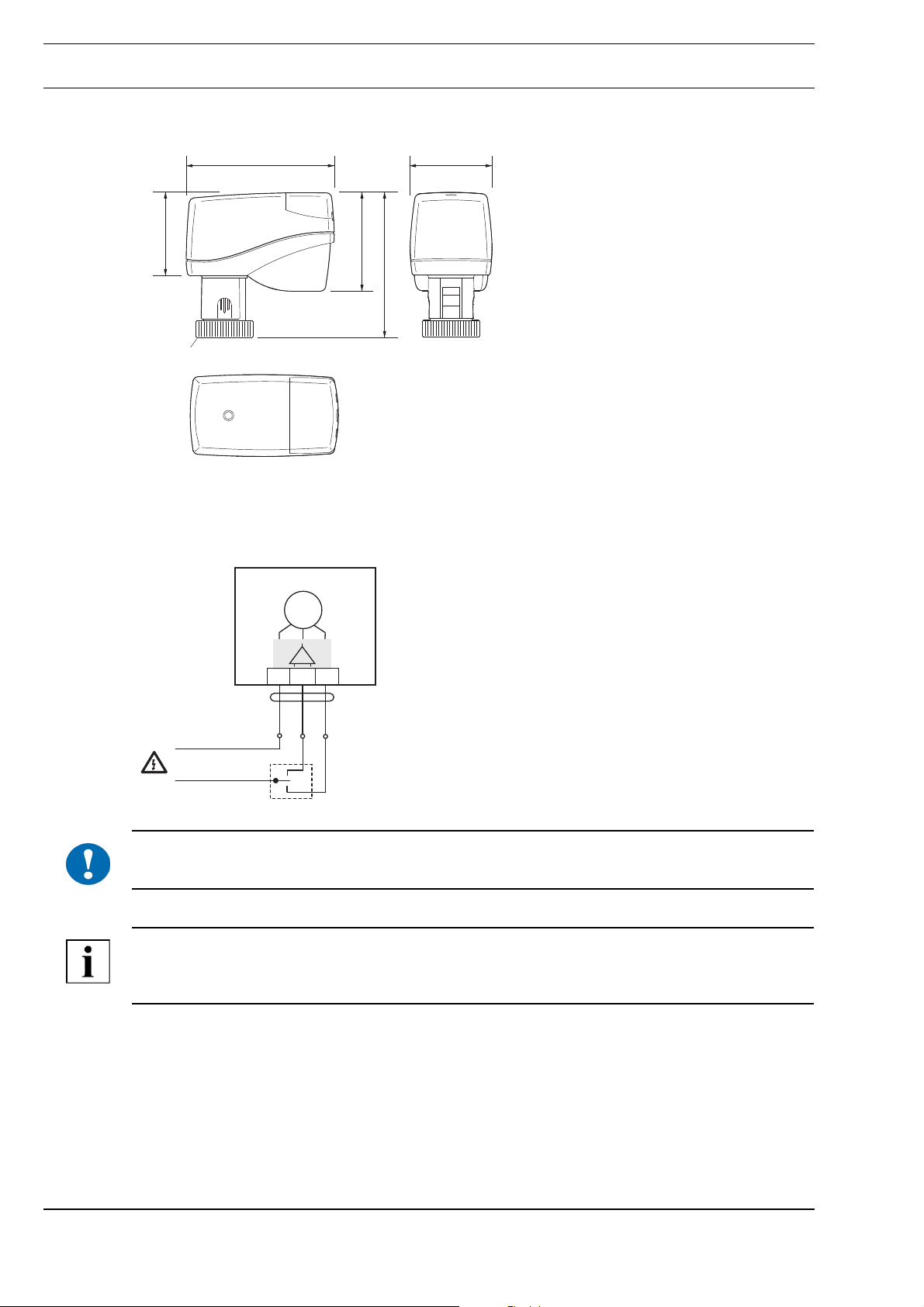
Dimensions
85 47
Connection
47,5
M30x1,5 DIN 13
- 3-point control
MD15/230
M
1
2
3
56,5
83
!
WH
BN
0 V AC
230 V AC
NOTICE
A 1 A pre-fuse is required to operate the small actuator.
NOTE
The actuation direction can be changed by switching the supply lines to terminals 2 and 3 on the
actuator.
GN
A
Page 4 / 12
Page 5

Issue 2014-09-04
Datasheet 3.09-20.150-01-EN
RZ15..25 two-way valves and RWZ15..25 three-way valves with MD15/230 small actuator
Application
Brass two-way/three-way valves RZ/RWZ15–RZ/RWZ25 with small
actuator MD15/230 are used in zone post-treatment devices for heating,
ventilation and air conditioning systems with water temperatures of
0 °C–120 °C for 3-point control in room automation.
The small actuator is controlled with a 3-point signal.
Types
Brass two-way valve RZ15–RZ25 for water 0 °C–120 °C with small actuator MD15/230
DN PN Kvs p (bar) Positioning
time (s)
RZ15/0,25MD15/230 15 16 0,25 6,0 98 0,340
RZ15/0,4MD15/230 15 16 0,4 6,0 98 0,340
RZ15/0,63MD15/230 15 16 0,63 6,0 98 0,340
RZ15/1,0MD15/230 15 16 1,0 6,0 98 0,340
RZ15/1,6MD15/230 15 16 1,6 6,0 98 0,340
RZ15/2,5MD15/230 15 16 2,5 6,0 98 0,340
RZ20/4,0MD15/230 20 16 4,0 3,0 98 0,395
RZ25/6,3MD15/230 25 16 6,3 1,5 98 0,680
RZ25/8,0MD15/230 25 16 8,0 1,5 98 0,680
Weight (kg)
MD15/230Product Description
Brass three-way valve RWZ15–RWZ25 for water 0 °C–120 °C with small actuator MD15/230
DN PN Kvs p (bar) Positioning
time (s)
RWZ15/0,25MD15/230 15 16 0,25 6,0 98 0,350
RWZ15/0,4MD15/230 15 16 0,4 6,0 98 0,350
RWZ15/0,63MD15/230 15 16 0,63 6,0 98 0,350
RWZ15/1,0MD15/230 15 16 1,0 6,0 98 0,350
RWZ15/1,6MD15/230 15 16 1,6 6,0 98 0,350
RWZ15/2,5MD15/230 15 16 2,5 6,0 98 0,350
RWZ20/4,0MD15/230 25 16 4,0 3,0 98 0,425
RWZ25/6,3MD15/230 25 16 6,3 1,5 98 0,780
RWZ25/8,0MD15/230 25 16 8,0 1,5 98 0,780
Weight (kg)
Page 5 / 12
A
Page 6

Datasheet 3.09-20.150-01-EN Issue 2014-09-04
Product DescriptionMD15/230
Accessories
Not included.
Two Z... fittings are required for RZ15..25 two-way valves and three Z... fittings for RWZ15..25
three-way valves.
Z201 DN15 male thread fitting, 1/2" union nut, 3/8" nipple
Z202 DN20 male thread fitting, 3/4" union nut, 1/2" nipple
Z203 DN25 male thread fitting, 1 1/4" union nut, 1" nipple
Z204 DN15 solder fitting, 1/2" union nut, D 12 mm nipple
Z205 DN20 solder fitting, 3/4" union nut, D 15 mm nipple
Z206 DN25 solder fitting, 1 1/4" union nut, D 28 mm nipple
A
Page 6 / 12
Page 7

Issue 2014-09-04
Technical Data: RZ/RWZ15..25 valves
Nominal diameter DN 15–25
Pressure rating PN 16
Connection G 1/2A ..G 1 1/4A male thread
Characteristic curve RZ.. Same percentage
RWZ.. RWZ.. A AB = same percentage, BAB = linear
Actuating stroke 6.5 ± 0.5 mm
Leak rate In acc. with EN 1349, leakage class VI
Medium temperature Cold and hot water 0 °C–120 °C with antifreeze and anti-corrosive agents
(max. 50%), glycol, glycerin, ethylene glycol, propylene glycol, monoethyl-
ene, ethanol, methanol, Antifrogen® N + L.
Not to be used for media based on mineral oils.
Housing Two-way valve hot-pressed brass CW602N; Three-way valve permanent
mold casting CuZn362AI-B
Cone Brass
Valve stem Stainless steel
Adapter Stainless steel
Sealing elements EPDM
Datasheet 3.09-20.150-01-EN
MD15/230Product Description
Dimensions
G
Hub 6,5
M30 x1,5
8,6
8,5
H
G
B
L
M30 x1,5
G
L
RZ.. RWZ..
Hub 6,5
8,6
8,5
H
B1
Page 7 / 12
DN G L B B1 H
15 G 1/2A 56 18 24,5 32
20 G 3/4A 66 19 33 34
25 G 1 1/4A 76 26 38 46
Dimensions L to H in mm
A
Page 8

Datasheet 3.09-20.150-01-EN Issue 2014-09-04
Product DescriptionMD15/230
Valve principle
A
RZ.. RWZ..
Dimensions with valve and actuator
170
83
AB
B
170
83
DN15: 109
DN20: 111
DN25: 123
MD15xxRZ.. MD15xxRWZ..
DN15: 109
DN20: 111
DN25: 123
A
Page 8 / 12
Page 9

Issue 2014-09-04
Valve Installation
NOTICE
!
The valve may only be installed by qualified technicians. In addition to the generally applicable installation guidelines, the following items are to be observed:
■ The pipeline system and the fixture interior must be free of foreign objects. In the event of contam-
inated media, dirt collectors are to be inserted upstream of the valves with fine screens, mesh
width 0.25 mm.
■ There must be no tension between the valve and the pipeline connection.
■ To avoid eddy formations in the valve body, the valve should be installed in a straight section of
the pipe. A distance of 10 times the nominal diameter is recommended between the valve flange
and manifold or other similar parts.
■ The installation location is to be selected so that the ambient temperature at the actuator is kept
between 0 °C–+50°C.
■ When carrying out installation, the permissible max. pressure difference p and the specified
direction of flow must be observed (see table in "Types" section, as well as the "Valve Principle").
■ The three-way valves are to be used as mixing valves. Pay attention to the direction of flow (see
fig. "Valve Principle").
■ Once the valve is installed, make sure the ball in the valve seating can be moved easily by pushing
in the valve stem.
■ To install the actuator and remove the housing cover, approx. 170 mm of free space is required
above the actuator.
■ For safety reasons, do not suspend the small actuators under the valve.
■ Observe the direction arrow on the valve body. Inverting the direction of flow impairs control
behavior.
Datasheet 3.09-20.150-01-EN
MD15/230Product Description
M
M
M
Page 9 / 12
A
Page 10

Datasheet 3.09-20.150-01-EN Issue 2014-09-04
Product DescriptionMD15/230
Installation and Commissioning of the Small Actuator
CAUTION
Installation and commissioning work may only be carried out by qualified technicians.
If the valve is installed in the system, make sure that no differential pressure builds up in the valve
body before beginning work. If necessary, close the gate valve and turn off pumps. After the pipeline
has cooled off, the actuator can be installed.
Be sure to comply with VDE guidelines and local wiring regulations. The device is connected
according to the legally binding system circuit diagram.
NOTICE
!
Do not operate small actuator MD15/230 electrically without the valve.
11
2
3
4
180°
Klick
5
■ Place the small actuator on the threaded connection of the valve and tighten hand-tight with the
union nut.
■ Establish the electrical connection.
■ After the mains power supply has been switched on, an automatic initialization run takes place.
The small actuator moves into upper end position. Adaptation of the valve takes place with the
application of 230 V to lead "GN".
■ After installation and commissioning work is complete, the automatic coupling must be protected
with the dust cover (see fig. 4).
6
7
8
A
Page 10 / 12
Page 11

Issue 2014-09-04
Removal of the Small Actuator
CAUTION
Before beginning to remove the unit, make sure that no differential pressure builds up in the valve
body before beginning work. If necessary, close the gate valve and turn off pumps.
After the pipeline has cooled off, you can begin removal of the small actuator.
Datasheet 3.09-20.150-01-EN
MD15/230Product Description
180°
1
5
■ Disconnect the small actuator from the mains power supply. Then disconnect all electrical connec-
tions.
■ Remove the union nut.
■ Turn the dust cover far enough so you can press the safety button.
■ Push the safety button of the automatic coupling as far as it will go and hold down (see fig. 4).
■ Remove the small actuator from the valve.
2
3
4
Page 11 / 12
A
Page 12

Datasheet 3.09-20.150-01-EN Issue 2014-09-04
Product DescriptionMD15/230
Manual adjustment
NOTICE
!
!
Manual adjustment may only be performed when the actuator is installed.
■ The small actuator must be disconnected from the mains power supply
for manual operation.
■ Using a hexagon key (key socket 4 mm), the actuator can be moved
into any position.
NOTICE
If you manually adjust until the slip clutch responds, turn the hexagon key half a turn in the opposite
direction after the manually set stroke position has been reached.
A
Page 12 / 12
 Loading...