

Page 1

Kieback&Peter GmbH & Co. KG
Tempelhofer Weg 50, 12347 Berlin/Germany
Telefon: +49 30 60095-0, Telefax: +49 30 60095-164
www.kieback-peter.de, info@kieback-peter.com
MD15/230-HR, MD15/230-HE, MD15/230-DA
3.09-20.250-01-EN | 2018-08-06
Q
Product Description
MD15/230-HR, MD15/230-HE and MD15/230-DA Small actuator
For R15xx, R20xx, RW15x and Danfoss RA Series Valves
Application
Actuator for three-point control systems in zone post-treatment devices for
heating, ventilation and air conditioning systems.
Content Page
Important Information Regarding Product Safety ..................................................................................................2
Item........................................................................................................................................................................3
Technical Data.....................................................................................................................................................3
Dimensions ..........................................................................................................................................................4
Connection...........................................................................................................................................................5
R15xx, R20xx and RW15x Two-Way/Three-Way Valves for the MD15/230-HE Actuator ....................................6
Types ...................................................................................................................................................................6
Technical Data: Rxx and RWxx Valves ...............................................................................................................6
Valve Installation....................................................................................................................................................8
Mounting and Commissioning the Actuator ...........................................................................................................9
Dismounting the Actuator ....................................................................................................................................12
Manual adjustment ..............................................................................................................................................13
Initialization and adjustment to the valve stroke ..................................................................................................14
Page 2
Page 2 / 16
Product Description
MD15/230-HR, MD15/230-HE, MD15/230-DA
3.09-20.250-01-EN | 2018-08-06
Q
Important Information Regarding Product Safety
Safety Instructions
This data sheet contains information on installing and commissioning the product "MD15/230-HR,
MD15/230-HE, MD15/230-DA". Each person who carries out work on this product must have read
and understood this data sheet. If you have any questions that are not resolved by this data sheet,
you can obtain further information from the supplier or manufacturer.
If the product is not used in accordance with this data sheet, the protection provided will be impaired.
Applicable regulations must be observed when installing and using the device. Within the EU, these
include regulations regarding occupational safety and accident prevention as well as those from the
VDE (Association for Electrical, Electronic & Information Technologies). If the device is used in other
countries, it is the responsibility of the system installer or operator to comply with local regulations.
Mounting, installation and commissioning work on the devices may only be carried out by qualified
technicians. Qualified technicians are persons who are familiar with the described product and who
can assess given tasks and recognize possible dangers due to technical training, knowledge and
experience as well as knowledge of the appropriate regulations.
Legend
WARNING
Indicates a hazard of medium risk which can result in death or severe bodily injury if it is not avoided.
CAUTION
Indicates a hazard of low risk which can result in minor or medium bodily injury if it is not avoided.
!
CAUTION
Indicates a hazard of medium risk which can result in material damage or malfunctions if it is not
avoided.
NOTE
Indicates additional information that can simplify the work with the product for you.
Notes on Disposal
For disposal, the product is considered waste from electrical and electronic equipment (electronic
waste) and must not be disposed of as household waste. Special treatment for specific components
may be legally binding or ecologically sensible. The local and currently applicable legislation must be
observed.
Page 3

Page 3 / 16
MD15/230-HR, MD15/230-HE, MD15/230-DA
Product Description
3.09-20.250-01-EN | 2018-08-06
Q
Item
Technical Data
MD15/230-HE Small actuator for R15xx, R20xx and RW15x
radiator valves and other valves with an
M30x1.5 connection that were manufactured
by Heimeier, Honeywell-MNG, Junkers, Honeywell-Baukmann, Oventrop (2001 and later)
and Cazzaniga
MD15/230-DA Small actuator for radiator valves that were
manufactured by Danfoss of the RA-N, RA-FN
or RA-U series
MD15/230-HR Small actuator for valve series R15/x
andRW15/x (manufacturer Hora, series 216Z
and316Z) that were discontinued in 11-2015
Nominal voltage AC 230 V ±10%; 50/60 Hz
Power consumption Dimensioning: 4.4 VA
Nominal: MD15/230-DA 2.8 VA; MD15/230-HR 3.0 VA;
MD15/230-HE 2.6 VA
Switch-on current Max. 10 A for a short time
Control Three-point signal (open/stop/close) or two-point signal (open/close)
Connection Built-in cable: 1.5 m, 3 x 0.75 mm
2
Motor switch-off Actuator spindle: extending = load-dependent, retracting = load-dependent
Actuating noise <28 dB
Positioning stroke MD15/230-HE and MD15/230-DA: 3 mm; MD15/230-HR: 9 mm
Positioning time 22 s/mm
Positioning force MD15/230-DA nominal 100 N; MD15/230-HR nominal 240 N
MD15/230-HE nominal 140 N
Position indicator Stroke range scale
Manual adjustment Only when disconnected from the power supply
Socket for hexagon key on the actuator cover,
Key socket 4 mm
Permitted medium temperature in valve
0..120 °C
Ambient temperature 0..50° C
Ambient humidity During operation: 0..85 % r.h., non-condensing
Out of operation: 0..85 % r.h., non-condensing
Overvoltage category III
Level of contamination 2
Degree of protection IP40
Protection class II in accordance with EN 60730
Installation position Anywhere from vertical to horizontal
Maintenance Maintenance-free
Weight 242 g
Page 4
Page 4 / 16
Product Description
MD15/230-HR, MD15/230-HE, MD15/230-DA
3.09-20.250-01-EN | 2018-08-06
Q
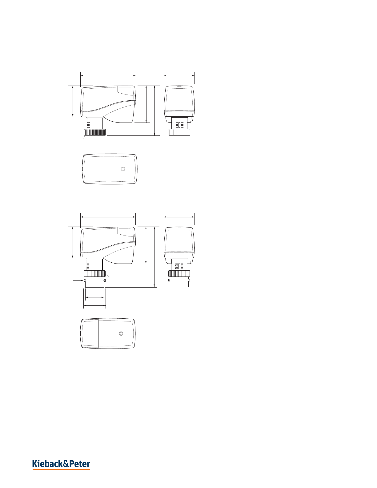
Dimensions
- MD15/230-HR and MD15/230-HE
-MD15/230-DA
85 47
56,5
47,5
76,5
M30 x 1,5 (MD15/230-HE)
M30 x 1 (MD15/230-HR)
85 47
56,5
47,5
94,5
M30x1,5 DIN 13
M4
Ø 25,0
Ø 30,0
Page 5
Page 5 / 16
MD15/230-HR, MD15/230-HE, MD15/230-DA
Product Description
3.09-20.250-01-EN | 2018-08-06
Q
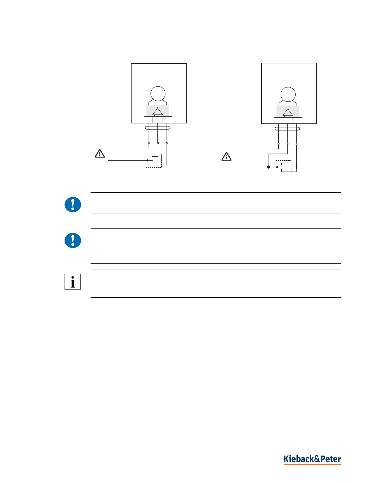
Connection
!
CAUTION
A 1 A pre-fuse is required to operate the actuator.
!
CAUTION
Temporary peak loads of up to 10 A may occur when switching on the actuator. Ensure suitability of
switching components (e.g. controller connection) to ensure proper functioning and to avoid malfunctions and damage.
NOTE
The actuation direction can be changed by switching the supply lines to terminals 2 and 3 on the
actuator.
- Three-point control - Two-point control
GY
230 V AC
BU BN
0 V AC
MD15/230-HR
MD15/230-HE
MD15/230-DA
M
1
2
3
MD15/230-HR
MD15/230-HE
MD15/230-DA
M
1
2
3
GY
230 V AC
BU
BN
0 V AC
Page 6

Page 6 / 16
Product Description
MD15/230-HR, MD15/230-HE, MD15/230-DA
3.09-20.250-01-EN | 2018-08-06
Q
R15xx, R20xx and RW15x Two-Way/Three-Way Valves for the MD15/230-HE Actuator
Types
PN10 gunmetal two-way valve for water up to 120 °C
PN10 gunmetal three-way valve for water up to 120 °C
Technical Data: Rxx and RWxx Valves
Type DN PN kvs R
Straight-through flow R10D 10 10 1.25 3/8"
R15D 15 10 1.35 1/2"
R20D 20 10 2.5 3/4"
Flow through 90° R10E 10 10 1.25 3/8"
R15E 15 10 1.35 1/2"
R20E 20 10 2.5 3/4"
Straight-through flow R10DV 10 10 0.73 3/8"
with Kvs setting R15DV 15 10 0.73 1/2"
R20DV 20 10 0.73 3/4"
Flow through 90° R10EV 10 10 0.73 3/8"
with Kvs setting R15EV 15 10 0.73 1/2"
R20EV 20 10 0.73 3/4"
Type DN PN kvs R
Connection left RW15L 10 10 1.45 1/2"
Connection right RW15R 15 10 1.45 1/2"
Nominal diameter DN10 - 20
Pressure rating PN10
Connection Pipe screw connections in accordance with DIN EN 2115
Actuating stroke 2 mm
Temperature of
medium
Water up to 120 °C
Housing Gunmetal; nickel-plated
Cone EPDM
Valve spindle Stainless steel
Spindle seal EPDM
Maintenance Maintenance-free
R10..20D, R10..20DV R10..20E, R10..20EV RW15L RW15R
Page 7

Page 7 / 16
MD15/230-HR, MD15/230-HE, MD15/230-DA
Product Description
3.09-20.250-01-EN | 2018-08-06
Q
Dimensions
Kvs default setting for R10 - 20DV/EV valves
To adjust to the heat requirement, the R10 - 20DV/EV valves have 8 flow settings for the radiator
mass flow rate.
The maximum flow rate, Kvs value (m³/h) can be selected by using the settings 1, 2, 3, 4, 5, 6, 7 or
8 (delivery setting = 8, corresponds to a Kvs value = 0.86).
The setting can be made using a Z29 socket key (accessory). The setting between 1 and 8 can be
read from the valve, and will be implemented by the installed small actuator.
Position 1 2 3 4 5 6 7 8
Kvs value 0,049 0,102 0,185 0,313 0,420 0,565 0,740 0,860
(1) Setting marks
(2) Z29 socket key (accessory)
1
2
Page 8

Page 8 / 16
Product Description
MD15/230-HR, MD15/230-HE, MD15/230-DA
3.09-20.250-01-EN | 2018-08-06
Q
Valve Installation
!
CAUTION
The valve may only be installed by qualified technicians. In addition to the generally applicable installation guidelines, the following items are to be observed:
■ The pipeline system and the fixture interior must be free of foreign objects. In the event of contam-
inated media, dirt collectors are to be inserted upstream of the valves with fine screens, mesh width
0.25 mm.
■ There must be no tension between the valve and the pipeline connection.
■ To avoid eddy formations in the valve body, the valve should be installed in a straight section of the
pipe. A distance of 10 times the nominal diameter is recommended between the valve flange and
manifold or other similar parts.
■ The installation location is to be selected so that the ambient temperature at the actuator is kept
between 0 °C–+50°C.
■ When carrying out installation, the permissible max. pressure difference p and the specified
direction of flow must be observed (see table in "Types" section, as well as the "Valve Principle").
■ The three-way valves are to be used as mixing valves. Pay attention to the direction of flow (see
fig. "Valve Principle").
■ Once the valve is installed, make sure the ball in the valve seating can be moved easily by pushing
in the valve stem.
■ To install the actuator and remove the housing cover, approx. 170 mm of free space is required
above the actuator.
■ For safety reasons, do not suspend the small actuators under the valve.
■ Observe the direction arrow on the valve body. Inverting the direction of flow impairs control
behavior.
M
M
M
Page 9

Page 9 / 16
MD15/230-HR, MD15/230-HE, MD15/230-DA
Product Description
3.09-20.250-01-EN | 2018-08-06
Q
Mounting and Commissioning the Actuator
WARNING
Contact with live parts of electrical domestic installation can cause death due to electric shock.
Mounting/removal may only be carried out when power is switched off.
CAUTION
Installation and commissioning work may only be carried out by qualified technicians.
If the valve is installed in the system, make sure that no differential pressure builds up in the valve
body before beginning work. If necessary, close the gate valve and turn off pumps. After the pipeline
has cooled off, the actuator can be installed.
Be sure to comply with VDE guidelines and local wiring regulations. The device is connected
according to the legally binding system circuit diagram.
!
CAUTION
Do not operate the MD15/230-HR, MD15/230-HE, MD15/230-DA Small Actuator electrically
without a valve.
Installation: MD15/230-HR and MD15/230-HE
≤ 90°
1 2 3 4
Page 10

Page 10 / 16
Product Description
MD15/230-HR, MD15/230-HE, MD15/230-DA
3.09-20.250-01-EN | 2018-08-06
Q
► Place the actuator on the threaded connection of the valve and tighten hand-tight using the union
nut.
► Establish the electrical connection.
► The first time the line power is switched on, an automatic initialization run takes place. The
actuator first travels to the upper end position and then to the lower end position. The valve is now
adapted.
The actuator will not respond to the control signal until the initialization run is complete.
!
CAUTION
After recommissioning or a manual adjustment, an initialization run must be triggered manually. This
is done by flipping the DIP switch before switching on the power supply (see Fig. 6).
Installation: MD15/230-DA
1
2
3
5 6 7
≤ 90°
1 2 3 4
5 6 7
1
2
3
8
Page 11

Page 11 / 16
MD15/230-HR, MD15/230-HE, MD15/230-DA
Product Description
3.09-20.250-01-EN | 2018-08-06
Q
► Place the valve adapter onto the valve and tighten the hexagon socket screw.
► Place the actuator on the threaded connection of the valve and tighten hand-tight using the union
nut.
► Establish the electrical connection.
► The first time the line power is switched on, an automatic initialization run takes place. The
actuator first travels to the upper end position and then to the lower end position. The valve is
now adapted.
The actuator will not respond to the control signal until the initialization run is complete.
!
CAUTION
After recommissioning or a manual adjustment, an initialization run must be triggered manually. This
is done by flipping the DIP switch before switching on the power supply (see Fig. 9).
9 10
Page 12

Page 12 / 16
Product Description
MD15/230-HR, MD15/230-HE, MD15/230-DA
3.09-20.250-01-EN | 2018-08-06
Q
Dismounting the Actuator
CAUTION
Before beginning to remove the unit, make sure that no differential pressure builds up in the valve
body before beginning work. If necessary, close the gate valve and turn off pumps.
After the pipeline has cooled off, you can begin removal of the small actuator.
Dismounting: M15/230-HR and MD15/230-HE
► Move the actuator to the center position using a control signal.
► Disconnect the small actuator from the mains power supply. Then disconnect all electrical
connections.
► Remove the union nut.
► Remove the small actuator from the valve.
50%
1 2 3 4
5
Page 13

Page 13 / 16
MD15/230-HR, MD15/230-HE, MD15/230-DA
Product Description
3.09-20.250-01-EN | 2018-08-06
Q
Dismounting: MD15/230-DA
► Move the actuator to the center position using a control signal.
► Disconnect the small actuator from the mains power supply. Then disconnect all electrical
connections.
► Remove the union nut.
► Remove the small actuator from the valve.
► Loosen the hexagon socket screw on the valve adapter.
► Remove the valve adapter.
50%
1 2 3 4
5 6 7
Page 14

Page 14 / 16
Product Description
MD15/230-HR, MD15/230-HE, MD15/230-DA
3.09-20.250-01-EN | 2018-08-06
Q
Manual adjustment
!
CAUTION
Manual adjustment may only be performed when the actuator is installed.
■ The small actuator must be disconnected from the mains power supply
for manual operation.
■ Using a hexagon key (key socket 4 mm), the actuator can be moved
into any position.
!
CAUTION
If you manually adjust until the slip clutch responds, turn the hexagon key half a turn in the opposite
direction after the manually set stroke position has been reached.
NOTE
An initialization run must be performed after a manual adjustment, see Reinitialization section on p.14
Page 15

Page 15 / 16
MD15/230-HR, MD15/230-HE, MD15/230-DA
Product Description
3.09-20.250-01-EN | 2018-08-06
Q
Initialization and adjustment to the valve stroke
WARNING
Contact with live components of the building’s electrical system can cause death due to electric
shock.
The actuator must be disconnected from the power supply before you remove the terminal cover and
flip the switch.
Reinitialization
The valve stroke must be reinitialized whenever the unit is remounted
or adjusted manually.
► Disconnect the actuator from the power supply and remove the
terminal cover.
► Change the switch position (1).
► Replace the terminal cover and reconnect the power supply.
The actuator will perform an initialization run.
NOTE
A valve stroke initialization is also performed when a valve end position is reached during normal
operation.
1
Page 16

Page 16 / 16
Product Description
MD15/230-HR, MD15/230-HE, MD15/230-DA
3.09-20.250-01-EN | 2018-08-06
Q
 Loading...