

Page 1

Issue 2012-05-09
Datasheet 1.10-51.111-01-EN
Product Description
DDC111 and DDC111-2 room control modulel
Application
The room control modules are used together with the technolon® RCNxxx-L
or FBR110-L room controllers. A room control module can be connected to
each technolon® room controller.
DDC111-2 with LCD display for indication of room temperature and operating
buttons for manual setting of the room temperature setpoint and switching
between three fan levels.
The DDC111 room control module also has operating buttons for switching
between day, night and stand-by modes.
DDC111, DDC111-2
DDC111-2
DDC111
Content Page
Important Information Regarding Product Safety ..................................................................................................2
Item........................................................................................................................................................................3
Technical Data.....................................................................................................................................................3
Accessories (not included in delivery) .................................................................................................................3
Dimensions..........................................................................................................................................................4
Connection...........................................................................................................................................................4
Mounting ................................................................................................................................................................5
Operation ...............................................................................................................................................................6
DDC111-2 Operation ...........................................................................................................................................6
DDC111 Operation ..............................................................................................................................................7
Änderungen vorbehalten - Contents subject to change - Sous réserve de modifications - Reservado el derecho a modificación - Wijzigingen
voorbehouden - Con riserva di modifiche - Innehåll som skall ändras - Změny vyhrazeny - Zmiany zastrzeżone - Возможны изменения
A változtatások jogát fenntartjuk -
Kieback&Peter GmbH & Co. KG
Tempelhofer Weg 50, 12347 Berlin/Germany
Telefon: +49 30 60095-0, Telefax: +49 30 60095-164
www.kieback-peter.de, info@kieback-peter.com
保留未经通知而改动的权力
A
-
Page 2
Datasheet 1.10-51.111-01-EN Issue 2012-05-09
Product DescriptionDDC111, DDC111-2
Important Information Regarding Product Safety
Safety Instructions
This data sheet contains information on installing and commissioning the product "DDC111,
DDC111-2". Each person who carries out work on this product must have read and understood this
data sheet. If you have any questions that are not resolved by this data sheet, you can obtain further
information from the supplier or manufacturer.
If the product is not used in accordance with this data sheet, the protection provided will be impaired.
Applicable regulations must be observed when installing and using the device. Within the EU, these
include regulations regarding occupational safety and accident prevention as well as those from the
VDE (Association for Electrical, Electronic & Information Technologies). If the device is used in other
countries, it is the responsibility of the system installer or operator to comply with local regulations.
Mounting, installation and commissioning work on the devices may only be carried out by qualified
technicians. Qualified technicians are persons who are familiar with the described product and who
can assess given tasks and recognize possible dangers due to technical training, knowledge and
experience as well as knowledge of the appropriate regulations.
Legend
WARNING
Indicates a hazard of medium risk which can result in death or severe bodily injury if it is not avoided.
!
CAUTION
Indicates a hazard of low risk which can result in minor or medium bodily injury if it is not avoided.
NOTICE
Indicates a hazard of medium risk which can result in material damage or malfunctions if it is not
avoided.
NOTE
Indicates additional information that can simplify the work with the product for you.
Notes on Disposal
For disposal, the product is considered waste from electrical and electronic equipment (electronic
waste) and must not be disposed of as household waste. Special treatment for specific components
may be legally binding or ecologically sensible. The local and currently applicable legislation must be
observed.
A
Page 2 / 8
Page 3
Issue 2012-05-09
Datasheet 1.10-51.111-01-EN
DDC111, DDC111-2Product Description
Item
DDC111-2 Room control module with LCD display for indication of room temperature, allows manual set-
ting of the room temperature setpoint and switching between three fan levels.
DDC111 Room control module with LCD display for indication of room temperature, allows manual set-
ting of the room temperature setpoint, switching between day, night and stand-by modes, and
switching between three fan levels.
Technical Data
Measured variable Room temperature of spaces in homes or commercial premises
Measuring system Integrated digital room sensor
Measuring range 0 °С to 45 °C
Connection RJ socket
Display LCD display:
■ Room temperature actual value 0.0 °C to 45.0 °C, in steps of 0.1 K
■ Room temperature setpoint, in steps of 0.1 K
■ Symbol display to indicate operating mode
■ Fan levels
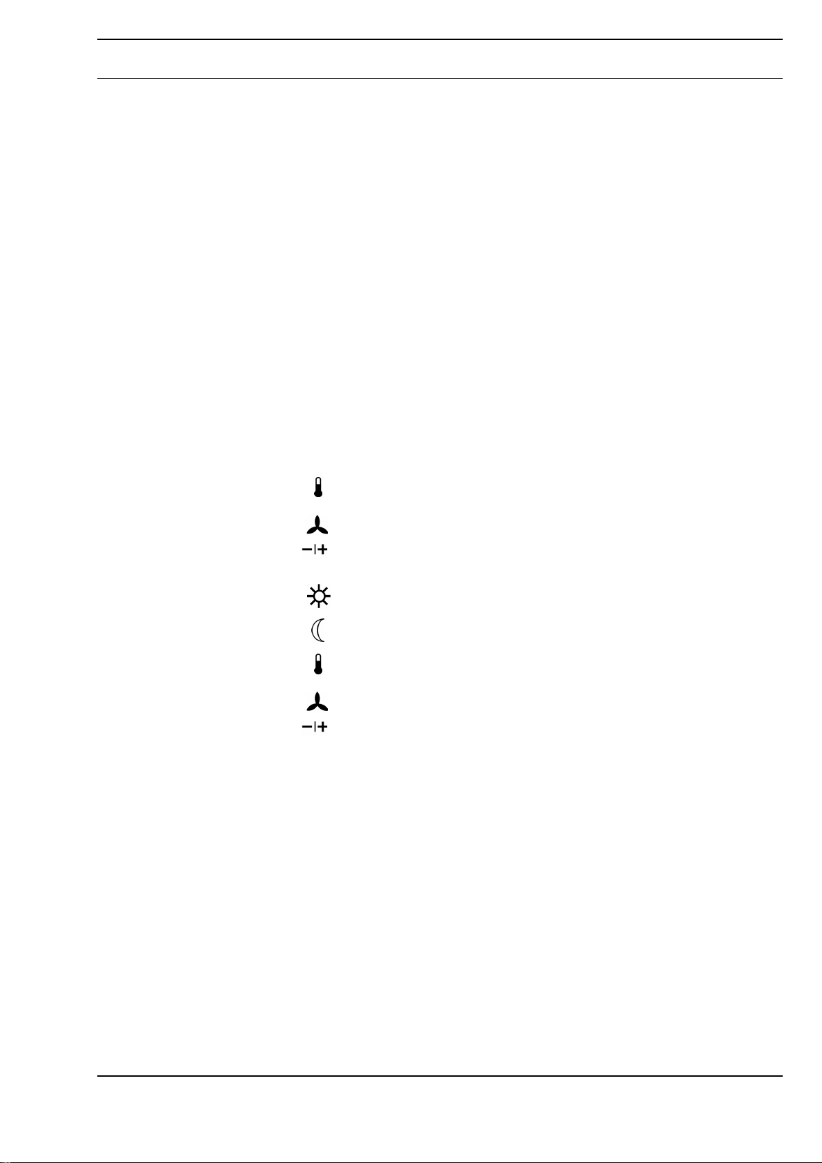
DDC111-2 operating buttons button: Switches to temperature mode for setting the room temperature
setpoint
button: Switches to fan mode for setting the fan level
button: Sets the room temperature setpoint or allows manual setting of
the fan level
DDC111 operating buttons button: Switches to day mode
button: Switches to night mode or to stand-by mode
button: Switches to temperature mode for setting the room temperature
setpoint
button: Switches to fan mode for setting the fan level
button: Sets the room temperature setpoint or allows manual setting of
the fan level
Housing Plastic housing, color RAL9010 (pure white), other colors available on request
Degree of protection IP30
Ambient temperature 0 °C to 45 °C
Ambient humidity Non-condensing
Installation Flush-mounted box
Dimensions WxHxD: 82.5 x 82.5 x 30.0 mm
Weight 110 g
Accessories (not included in delivery)
Z178 Connection line: room control module <> room controller (RJ plug on both sides, 10 m)
Z178/2 Adapter: RJ plug - terminal block, 4-pole (15 cm)
Page 3 / 8
A
Page 4
Datasheet 1.10-51.111-01-EN Issue 2012-05-09
Product DescriptionDDC111, DDC111-2
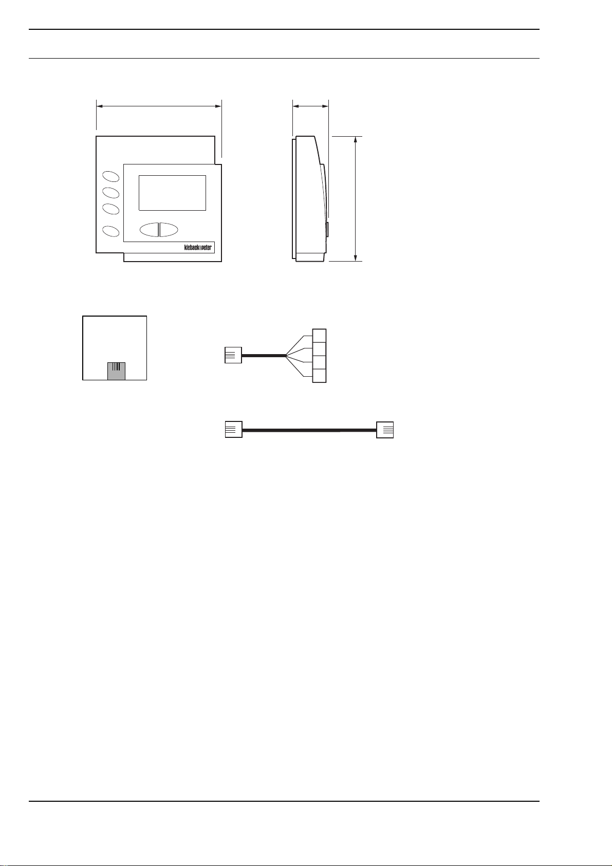
Dimensions
82,5 28,3
82,5
Connection
DDC111-2
DDC111
RJ9
Z178/2
RJ9
Z178
RJ9
15 cm
sw
rt
gr
gl
10 m
0V=
Rx
Tx
5V=
RJ9
A
Page 4 / 8
Page 5
Issue 2012-05-09
Mounting
Datasheet 1.10-51.111-01-EN
DDC111, DDC111-2Product Description
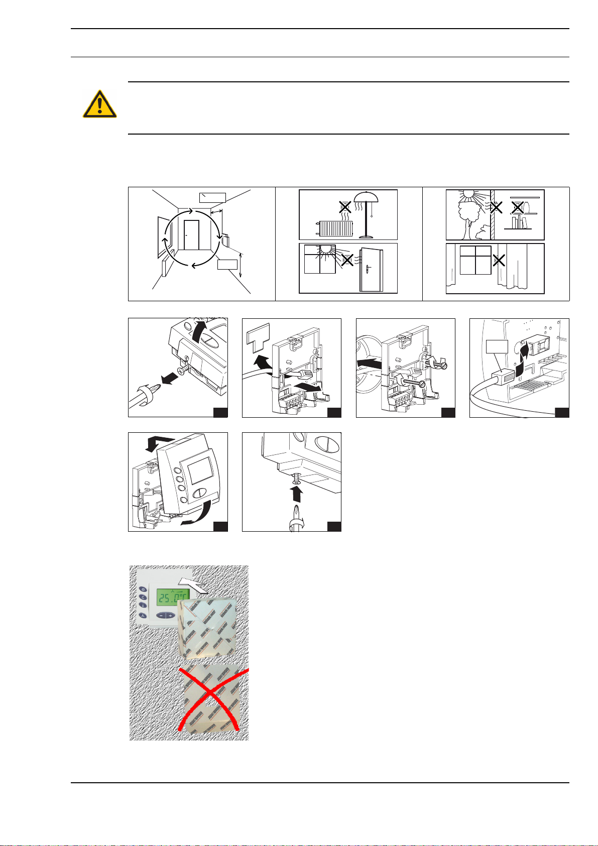
WARNING
Contact with live parts of electrical domestic installation can cause death due to electric shock.
Mounting/removal may only be carried out when power is switched off.
The room control module can be mounted on the wall or onto a flush-mounted box.
Choose an installation location that is subject to the air flow of the room to ensure that the room
controller can quickly and accurately measure the room temperature.
= 0,5m
1,5m
Protective cover
1 2 3
5 6
The packaging box serves as a protective cover for the construction phase. Fold the side flaps inward and tear off the
lid of the box.
Z178
Z178/2
4
Page 5 / 8
A
Page 6
Datasheet 1.10-51.111-01-EN Issue 2012-05-09
Product DescriptionDDC111, DDC111-2
Operation
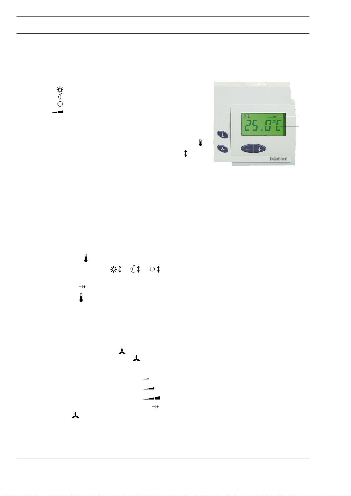
DDC111-2 Operation
Displays
Function symbols depend on operating mode:
Day mode
Night mode
Stand-by mode
Fan levels
Automatic switching via central program or presence detector
LCD display depends on configuration:
■ Room temperature (actual value) with function symbol
■ Room temperature setpoint with function symbol
1 Function symbols
2 LCD display
1
2
Adjusting the room temperature setpoint
The room temperature setpoint for day, night or stand-by mode is automatically specified by the
program. Depending on the configuration, the room temperature setpoint can be manually adjusted
between ± 3 K.
Manual setting adjusts the setpoints for all operating modes to the same extent.
Example: If the current “day” setpoint temperature is increased by 2 K, the “night” and “stand-by”
setpoints will also be increased by 2 K.
■ Press the button: The room control module switches to “Setpoint setting” temperature mode.
The function symbol or or is displayed, and the decimal place of the current setpoint
setting flashes at the same time.
■ Use the button to increase or decrease the room temperature setpoint in steps of 0.1 K.
■ Use the button to switch directly back to the standard display. If no button is pressed, the room
control module automatically switches back to the standard display after 5 seconds. The new room
temperature setpoint is saved.
Switching fan levels on or off
Fan levels are automatically switched on and off by the program. If necessary, fan levels can also be
switched manually by the user.
Manual control: Press the button: The room control module switches to the manually adjustable
fan mode. The function symbol is displayed, and the current fan setting flashes at the same time.
■ Fan off: No function symbol
■ Fan level 1: The function symbol
■ Fan level 2: The function symbol
■ Fan level 3: The function symbol
The new fan level can be set using the button.
Use the button to switch directly back to the standard display. If no button is pressed, the room
control module automatically switches back to the standard display after 5 seconds. The fan then
switches to the selected setting.
A
Page 6 / 8
Page 7
Issue 2012-05-09
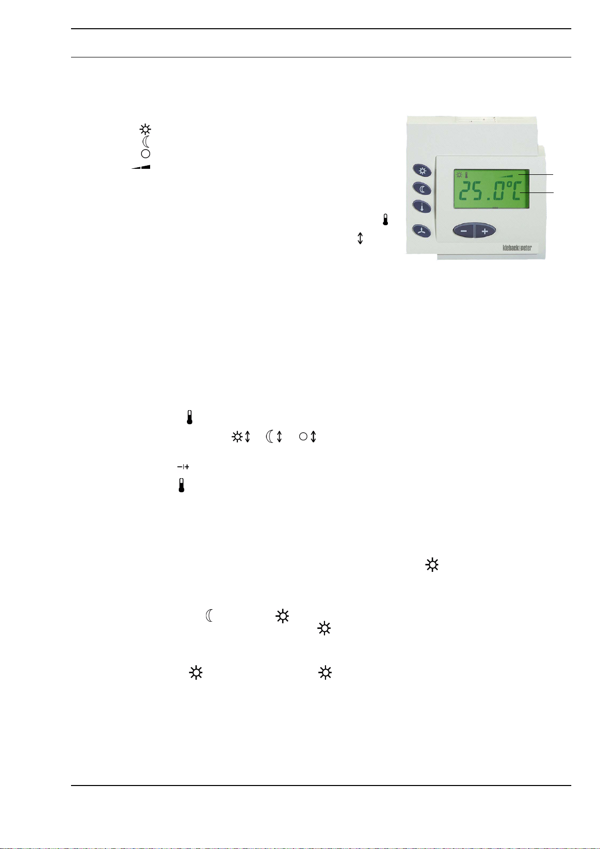
DDC111 Operation
Displays
Function symbols depend on operating mode:
Automatic switching via central program or presence detector
LCD display depends on configuration:
■ Room temperature (actual value) with function symbol
■ Room temperature setpoint with function symbol
Day mode
Night mode
Stand-by mode
Fan levels
Datasheet 1.10-51.111-01-EN
DDC111, DDC111-2Product Description
1
2
1 Function symbols
2 LCD display
Adjusting the room temperature setpoint
The room temperature setpoint for day, night or stand-by mode is automatically specified by the
program. Depending on the configuration, the room temperature setpoint can be manually adjusted
between ± 3 K.
Manual setting adjusts the setpoints for all operating modes to the same extent.
Example: If the current “day” setpoint temperature is increased by 2 K, the “night” and “stand-by”
setpoints will also be increased by 2 K.
■ Press the button: The room control module switches to “Setpoint setting” temperature mode.
The function symbol or or is displayed, and the decimal place of the current setpoint
setting flashes at the same time.
■ Use the button to increase or decrease the room temperature setpoint in steps of 0.1 K.
■ Use the button to switch directly back to the standard display. If no button is pressed, the room
control module automatically switches back to the standard display after 5 seconds. The new room
temperature setpoint is saved.
Switching on day or stand-by mode
The central program automatically switches night and stand-by modes on and off. Day mode is
switched on either by the presence detector or manually using the button.
Switching on day mode
Day mode can only be switched on manually in night or stand-by modes. When manually switching
from night mode to day mode the day mode is only switched on for a time period specified by
the program. At the end of this time period, the room module automatically switches back to night
mode.
Switching on day mode:
Page 7 / 8
■ Press the button: Function symbol is displayed. When switching from night mode to day
mode, the duration of the day mode that is switched on is displayed for 5 seconds.
A
Page 8

Datasheet 1.10-51.111-01-EN Issue 2012-05-09
Product DescriptionDDC111, DDC111-2
Stand-by mode
Stand-by mode can be switched on by a presence detector or manually only in day mode, e.g., when
leaving a room.
Switching on stand-by mode:
■ Press the button: Function symbol is displayed. Use the button to switch off stand-by
mode.
Switching fan levels on or off
Fan levels are automatically switched on and off by the program. If necessary, fan levels can also be
switched manually by the user.
Manual control: Press the button: The room control module switches to the manually adjustable
fan mode. The function symbol is displayed, and the current fan setting flashes at the same time.
■ Fan off: No function symbol
■ Fan level 1: The function symbol
■ Fan level 2: The function symbol
■ Fan level 3: The function symbol
The new fan level can be set using the button.
Use the button to switch directly back to the standard display. If no button is pressed, the room
control module automatically switches back to the standard display after 5 seconds. The fan then
switches to the selected setting.
A
Page 8 / 8
 Loading...