

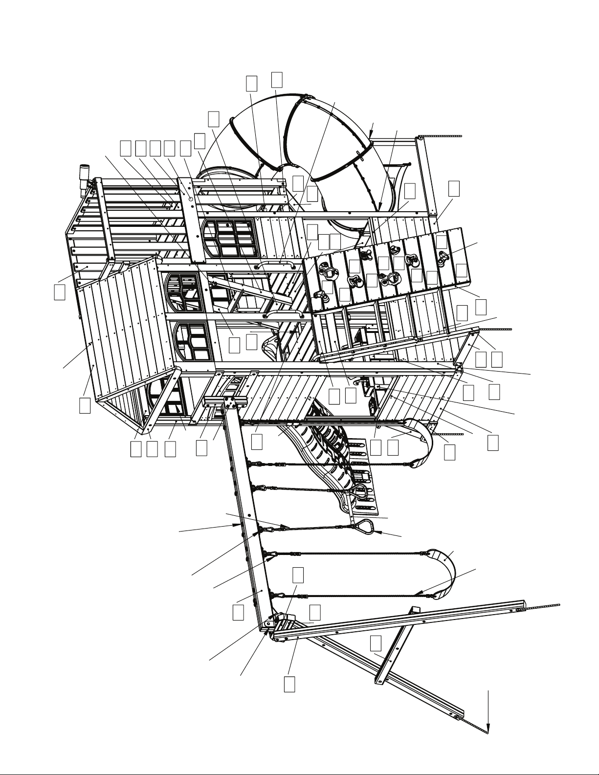
KidKraft Cedar Summit COPPER RIDGE PLAYSET Installation And Operating Instructions Manual
974cm
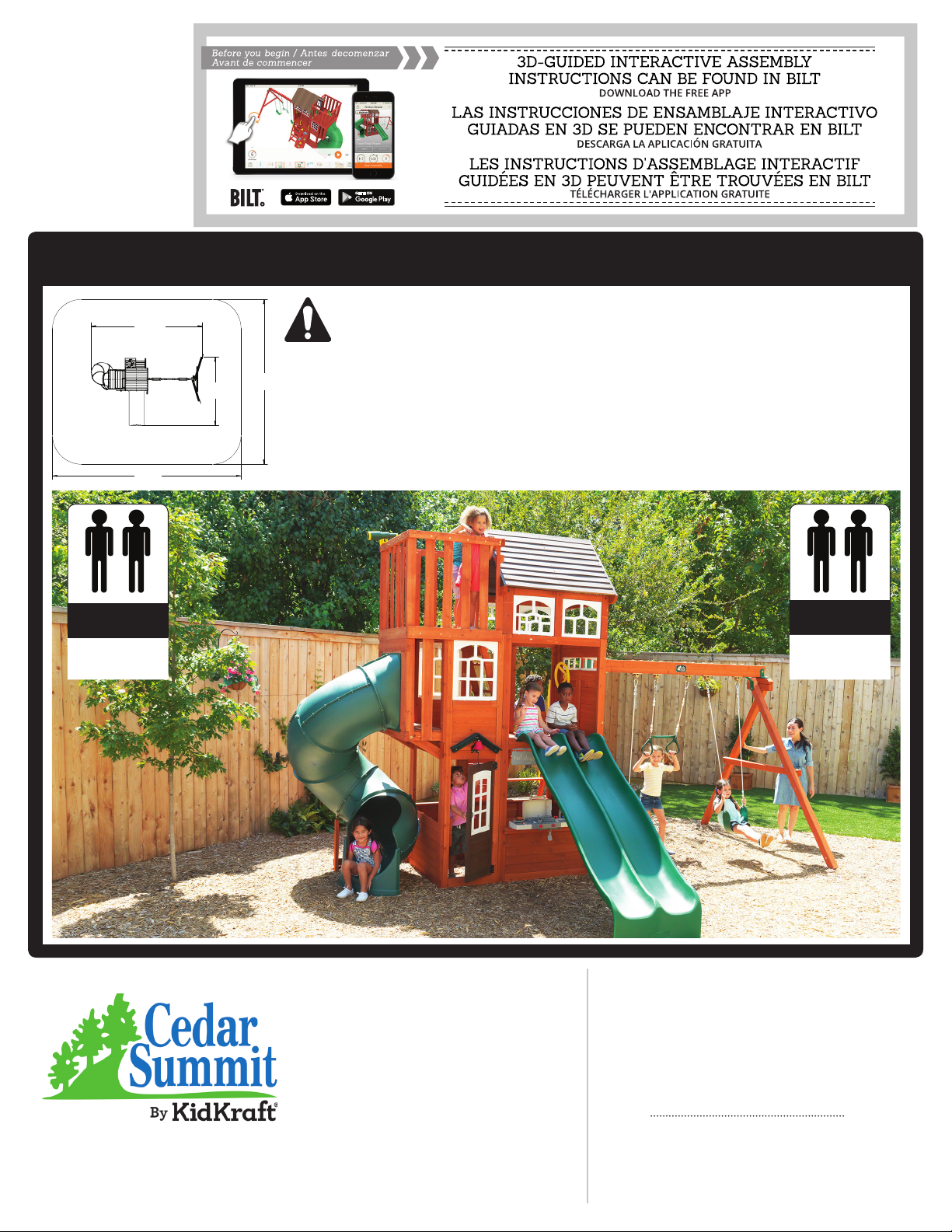
F29055 - Copper Ridge Playset Safety Zone
COPPER
RIDGE
PLAYSET
F29055E
INSTALLATION AND OPERATING INSTRUCTIONS
To reduce the risk of serious injury or death, you must read and
18' 8.6"
574cm
5.705 m
32' 6"
9.9 m
10 - 12 Hrs
10 - 12 Hrs
1 - 2 Hrs
2-4 Hrs
FOR FORT & SWING
FOR FORT & SWING
TUBE SLIDE
TWO PERSON
ASSEMBLY
11' 7.56"
354cm
3.545 m
WARNING
Manufacturer contact informaon provided below.
OBSTACLE FREE SAFETY ZONE - 32’ 6” x 27’11” (9.9 x 8.51 m) area requires Protecve Surfacing. See page 3.
27' 11"
851cm
8.51 m
MAXIMUM VERTICAL FALL HEIGHT - 7’ 8” (2.34m)
CAPACITY - 16 Users Maximum, Ages 3 to 10; Weight Limit 110 lbs. (49.9 kg) per child.
RESIDENTIAL HOME USE ONLY. Not intended for public areas such as mul-unit residences, schools, churches,
nurseries, day cares or parks.
Warning. Only for domesc use.
follow these instrucons. Keep and refer to these instrucons
oen and give them to any future owner of this play set.
14 - 18 Hrs
FOR FORT & SWING
TWO PERSON
ASSEMBLY
For Outdoor Family Domestic Use Only
Cedar Summit by KidKraft
4630 Olin Road
Dallas, TX 75244, United States
customersupport@kidkraft.com
Online Parts Replacement:
Cedarsummitplay.com/parts-center-warranty-claim
Customer Service:
1(800) 933-0771 or (972) 385-0100
KidKraft Netherlands BV
Olympisch Stadion 29
1076DE Amsterdam, The Netherlands
Europe Customer Service: +31 (0)20 305 8620
europecustomerservice@kidkraft.com
EU Online Parts Replacement: parts.kidkraft.eu
Table of Contents
Warnings and Safe Play Instructions ..........pg. 2
Protective Surfacing Guidelines. . . . . . . . . . . . . . . pg. 3
Instructions for Proper Maintenance .........pg. 4
About Our Wood – Limited Warranty .........pg. 5
Keys to Assembly Success ....................pg. 6
Part ID pg. 10-19
Step-By-Step Instructions ...................pg. 20
Installation of I.D./Warning Plaque ......Final Step
Rev 10/23/2018
Warnings and Safe Play Instructions
CONTINUOUS ADULT SUPERVISION REQUIRED. Most serious injuries and deaths on playground equipment have occurred
while children were unsupervised! Our products are designed to meet mandatory and voluntary safety standards. Complying
with all warnings and recommendations in these instructions will reduce the risk of serious or fatal injury to children using
this play system. Go over the wa
understand and follow them. Remember on-site adult supervision is required for children of all ages.
rnings and safe play instructions regularly with your children and make certain that they
WARNING
SERIOUS HEAD INJURY HAZARD
Installation over concrete, asphalt, dirt, grass, carpet
and other hard surface creates a risk of serious injury
or death from falls to the ground. Install and maintain
shock absorbing material under and around play-set as
recommended on page 3 of these instructions.
COLLISION HAZARD
Place play-set on level ground at least 2m from any
obstruction such as a garage or house, fences, poles,
trees, sidewalks, walls, landscape ti
pavement, planters, garden borders, overhanging
branches, laundry lines, and electrical wires. (See
OBSTAC
CHOKING HAZARD/SHARP EDGES & POINTS
Adult assembly required. This product contains small
parts and parts with sharp edges and points. Keep parts
away from children until fully assembled.
WARNING LABEL
Owners shall be responsible for maintaining the legibility
o
LE FREE SAFETY ZONE on cover)
f the warning labels.
mbers, rocks,
STRANGULATION HAZARD
,senilsehtolc ,sepor htiw yalp ot nerdlihc wolla REVEN •
pet leashes, cables, chains or cord-like items when using
this play-set or to attach these items to play-set.
ponchos, hoods, scarves, capes, necklaces, items with
draw-strings, cords or ties when using this play-set.
stemleh trops ro ekib raew ot nerdlihc wolla REVEN •
when using this play-set.
Failure to prohibit these items, even helmets with chin
straps, increases the risk of serious injury and death to
children from entanglement and strangulation.
TIP OVER HAZARD
Choose a level location for the equipment. This can reduce
the likelihood of the p
surfacing materials washing away during heavy rains.
D
O NOT allow children to play on the play-set until the
assembly is complete and the unit is properly anchored.
Never add extra length to chain or rope. The chains or ropes
provided are the maximum length designed for the
swinging element(s)
lay set tipping over and loose-fill
WARNING
front cover.
footwear.
of the swing seat to prevent erratic swing motion or
falling off.
loose, or sharp edged hardware. Replace, tighten and or
sand smooth as required prior to playing.
or cable are secured at both ends and cannot be looped
back on itself as to create an entanglement hazard.
plastic rides to assure that they are not very hot as to
cause burns. Cool hot slide and rides with water and wipe
dry prior to using.
Orientate slide such that it gets the least amount of exposure
to the sun.
– Safe Play Instructions
eeS .tes-yalp ruoy fo snoitatimil yticapac evresbO
gnisolcne toof lluf dna gnittfi llew htiw nerdlihc sserD
retnec eht ni thgiew lluf rieht htiw tis ot nerdlihc hcaeT
,gnissim ;doow dekcarc ro nekorb ,deretnilps rof kcehC
rehto dna edils eht kcehc ,syad toh ro dna ynnus nO
raewtoof leeh ro eot nepo raew ot nerdlihc wolla ton oD
like sandals, flip–flops or clogs.
dniheb ,neewteb ,tnorf ni ,klaw ot nerdlihc wolla ton oD
or close to moving rides.
pool ro sepor ro sniahc gniws tsiwt nerdlihc tel ton oD
them over the top support bar. This may reduce the
strength of the chain or rope and cause premature failure.
.noitom ni era yeht elihw sedir ffo teg nerdlihc tel ton oD
.tew si ti nehw tnempiuqe no gnibmilc timrep ton oD
niahc ,sreddal epor ,sepor gnibmilc dednepsus taht yfireV
manner for which it was not intended. Standing on or
jumping from the roof, elevated platforms, swings,
climbers, ladders or slide can be dangerous.
run up slide.
a ni tnempiuqe fo esu ro yalp hguor timrep ton oD
.staes ro sedir ytpme gniws ot nerdlihc wolla ton oD
ro tsrfi daeh edils nwod og ot nerdlihc wolla ton oD
2
Protective Surfacing - Reducing Risk of Serious Head Injury From Falls.
One of the most important things you can do to reduce the likelihood of serious head injuries is to install shock-absorbing
protective surfacing under and around your play equipment. The protective surfacing should be applied to a depth that is suitable
for the equipment height in accordance with ASTM F1292. There are different types of surfacing to choose from; whichever
product you select, follow these guidelines:
Loose-Fill Materials
• Maintain a minimum depth of 9 inches of loose-fill materials such as wood mulch/chips, engineered wood fiber (EWF), or
shredded/recycled rubber mulch for equipment up to 8 feet high; and 9 inches of sand or pea gravel for equipment up to 5 feet
high. NOTE: An initial fill level of 12 inches will compress to about a 9-inch depth of surfacing over time. The surfacing will also
compact, displace, and settle, and should be periodically raked and refilled to maintain at least a 9-inch depth.
• Use a minimum of 6 inches of protective surfacing for play equipment less than 4 feet in height. If maintained properly, this
should be adequate. (At depths less than 6 inches, the protective material is too easily displaced or compacted.)
NOTE: Do not install home playground equipment over concrete, asphalt, or any other hard surface. A fall onto a hard surface
can result in serious injury to the equipment user. Grass and dirt are not considered protective surfacing because wear and
environmental factors can reduce their shock absorbing effectiveness. Carpeting and thin mats are not adequate protective
surfacing. Ground level equipment -- such as a sandbox, activity wall, playhouse or other equipment that has no elevated play
surface -- does not need any protective surfacing.
• Use containment, such as digging out around the perimeter and/or lining the perimeter with landscape edging. Don’t forget to
account for water drainage.
• Periodically rake, check and maintain the depth of the loose-fill surfacing material. Marking the correct depth on the play
equipment support posts will help you to see when the material has settled and needs to be raked and or replenished. Be sure to
rake and evenly redistribute the surfacing in heavily used areas.
• Do not install loose fill surfacing over hard surfaces such as concrete or asphalt.
Poured-In-Place Surfaces or Pre-Manufactured Rubber Tiles
You may be interested in using surfacing other than loose-fill materials - like rubber tiles or poured-in-place surfaces.
• Installations of these surfaces generally require a professional and are not “do-it yourself” projects.
• Review surface specifications before purchasing this type of surfacing. Ask the installer/manufacturer for a report showing that
the product has been tested to the following safety standard: ASTM F1292 Standard Specification for Impact Attenuation of
Surfacing Materials within the Use Zone of Playground Equipment. This report should show the specific height for which the
surface is intended to protect against serious head injury. This height should be equal to or greater than the fall height - vertical
distance between a designated play surface (elevated surface for standing, sitting, or climbing) and the protective surfacing
below - of your play equipment.
• Check the protective surfacing frequently for wear.
Placement
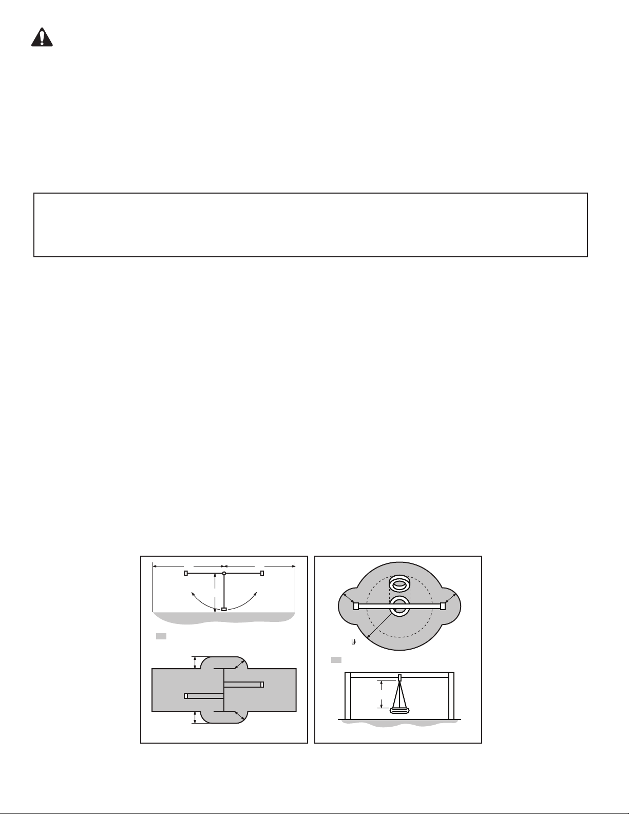
Proper placement and maintenance of protective surfacing is essential. Refer to diagram on front cover. Be sure to;
• Extend surfacing at least 2m from the equipment in all directions.
• For to-fro swings, extend protective surfacing in front of and behind the swing to a distance equal to twice the height of the top bar
from which the swing is suspended.
• For tire swings, extend surfacing in a circle whose radius is equal to the height of the suspending chain or rope, plus 6 feet in all
directions.
2H 2H
H
Denotes Use Zone with Protective Surfacing
6 ft.
6 ft.
Use Zone for Single-Axis Swings
6 ft.
6 ft.
6 ft. 6 ft.
6 ft.
Denotes Use Zone with Protective Surfacing
L
Use Zone for Multi-Axis Swings
From the CPSC Outdoor Home Playground Safety Handbook. At http://www.playgroundregs.com/resources/CPSC%20324.pdf
3
Instructions for Proper Maintenance
Your Cedar Summit Play System is designed and constructed of quality materials with your child’s safety in mind. As
with all outdoor products used by children, it will weather and wear. To maximize the enjoyment, safety and life of your
Play Set, it is important that you, the owner, properly maintain it.
Check the following at the beginning of the play season:
HARDWARE:
Check metal parts for rust. If found,
sand and repaint using a non-lead paint
complying with 16 CFR 1303.
Inspect and tighten all hardware. On
wood assemblies DO NOT OVERTIGHTEN as to cause crushing and
splintering of wood.
Check for sharp edges or protruding screw threads, add
washers if required.
If Bolt protrudes
beyond T-Nut
Use an extra
flat washer
SHOCK ABSORBING SURFACING:
Check for foreign objects. Rake and check depth of loose
fill protective surfacing materials to prevent compaction and
maintain appropriate depth. Replace as necessary.
(See Protective Surfacing, page 3)
GROUND STAKES (ANCHORS):
Check for looseness, damage or deterioration. Should firmly
anchor unit to ground during use. Re-secure and or replace,
if necessary.
SWING HANGERS:
Check that bolts are secure and tight. Quick clips should be
completely closed and threaded clips screwed tight.
If squeaking occurs lubricate bushings with oil or WD-40®.
SWINGS, ROPES AND RIDES:
Reinstall if removed during cold season. Check all moving
parts including swing seats, ropes, chains and attachments
for wear, rust and other deterioration. Replace as needed.
Check that ropes are tight, secure at both ends and cannot
loop back as to create an entrapment.
WOOD PARTS:
Check all wood members for deterioration, structural
damage and splintering. Sand down splinters and replace
deteriorated wood members. As with all wood, some
checking and small cracks in grain is normal.
Applying a water repellent or stain (water-based) on a yearly
basis is important maintenance to maintain maximum life
and performance of the product.
Check twice a month during play season:
HARDWARE:
Inspect for tightness. Must be firmly against, but not
crushing the wood. DO NOT OVER-TIGHTEN.
This will cause splintering of wood.
Check for sharp edges or protruding screw threads.
Add washers if required.
SHOCK ABSORBING SURFACING:
Rake and check depth of loose fill protective surfacing
materials to prevent compaction and maintain appropriate
depth. Replace as necessary.
(See Protective Surfacing, page 3)
Check once a month during play season:
SWING HANGERS:
Check that they are secure and orientated correctly. Hook
should rotate freely and perpendicular to support beam.
If squeaking occurs lubricate bushings with oil or WD-40®.
SWINGS AND RIDES:
Check swing seats, all ropes, chains and attachments for
fraying, wear, excessive corrosion or damage.
Replace if structurally damaged or deteriorated.
Check at the end of the play season:
SWINGS AND RIDES:
To prolong their life, remove swings and store inside when
outside temperature is below 32°F/0°C. Below freezing,
plastic parts may become more brittle.
If you dispose of your play set: Please disassemble and dispose of your unit so that it does not create any unreasonable
hazards at the time it is discarded. Be sure to follow your local waste ordinances.
SHOCK ABSORBING SURFACING:
Rake and check depth of loose fill protective surfacing
materials to prevent compaction and maintain appropriate
depth. Replace as necessary.
(See Protective Surfacing, page 3)
4
About Our Wood
Cedar Summit Premium Play Systems uses only premium playset lumber, ensuring the safest product for your children’s
use. Although we take great care in selecting the best quality lumber available, wood is still a product of nature and susceptible to
weathering which can change the appearance of your set.
What causes weathering? Does it affect the strength of my Play System?
One of the main reasons for weathering is the effects of water (moisture); the moisture content of the wood at the surface is
different than the interior of the wood. As the climate changes, moisture moves in or out of the wood, causing tension which can
result in checking and or warping. You can expect the following due to weathering. These changes will not affect the strength of
the product:
1. Checking is surface cracks in the
because the surface and interior moisture content will vary more widely than in thinner wood.
2. Warping results from any distortion (twisting, cupping) from the original plane of the board and often happens from rapid
wetting and drying of the wood.
3. Fading happens as a natural change in the wood color as it is exposed to sun-light and will turn a grey over time.
How can I reduce the amount of weathering to my Play System?
At the factory we have coated the wood with a water repellent or stain. This coating decreases the amount of water absorption
during rain or snow thus decreasing the tension in the wood. Sunlight will break down the coating, applying a water repellant or
stain on a yearly basis is important mainten
Most weathering is just the normal result of nature and will not affect safe play and enjoyment for your child. However if you are
concerned that a part has experienced a severe weathering problem please call our consumer relations department for further assistance.
warranty service.
wood along the grain. A post (4” x 4”) will experience more checking than a board (1” x 4”)
ance. (see your local stain and paint supplier for a recommended product)
10 Year Limited Warranty
Cedar Summit by KidKra warrants that this product is free from defect in materials and workmanship
for a period of one year from the original date of purchase. In addition, lumber is warranted for 10
years against structural failure due to rot and insect damage. All other parts, such as hardware, swings,
rides, accessories, and slides carry a one-year warranty only.
This warranty applies to the original owner and registrant and is non-transferable.
Regular maintenance is required to assure the integrity of your Play System. Failure by the owner
to maintain the product according to the maintenance requirements may void this warranty. This
warranty does not cover any inspection cost.
This Limited Warranty does not cover:
• Labour for replacement of any defective item(s);
• Incidental or consequential damages;
• Cosmetic defects which do not affect performance or integrity;
• Vandalism; improper use or installation; acts of nature;
• Minor twisting, warping, checking, or any other natural occurring properties of wood that do not
affect performance or integrity.
Cedar Summit by KidKraft products have been designed for safety and quality. Any modifications
made to the original product could damage the structural integrity of the unit leading to failure
possible injury. Cedar Summit by KidKraft cannot assume any responsibility for modified products.
Furthermore, modification voids any and all warranties.
This product is warranted for RESIDENTIAL USE ONLY. Under no circumstance should a Cedar Summit
by KidKra Play System be used in public settings such as schools, churches, playgrounds, parks, day cares
and the like. Such use may lead to product failure and potential injury. Any and all public use will void this
warranty.
Cedar Summit by KidKraft disclaims all other representations and warranties of any kind, express or implied
and
.
province to province. This warranty excludes all consequential damages, however, some states do not allow the
limitation or exclusion of consequential damages, and therefore this limitation may not apply to you.
5
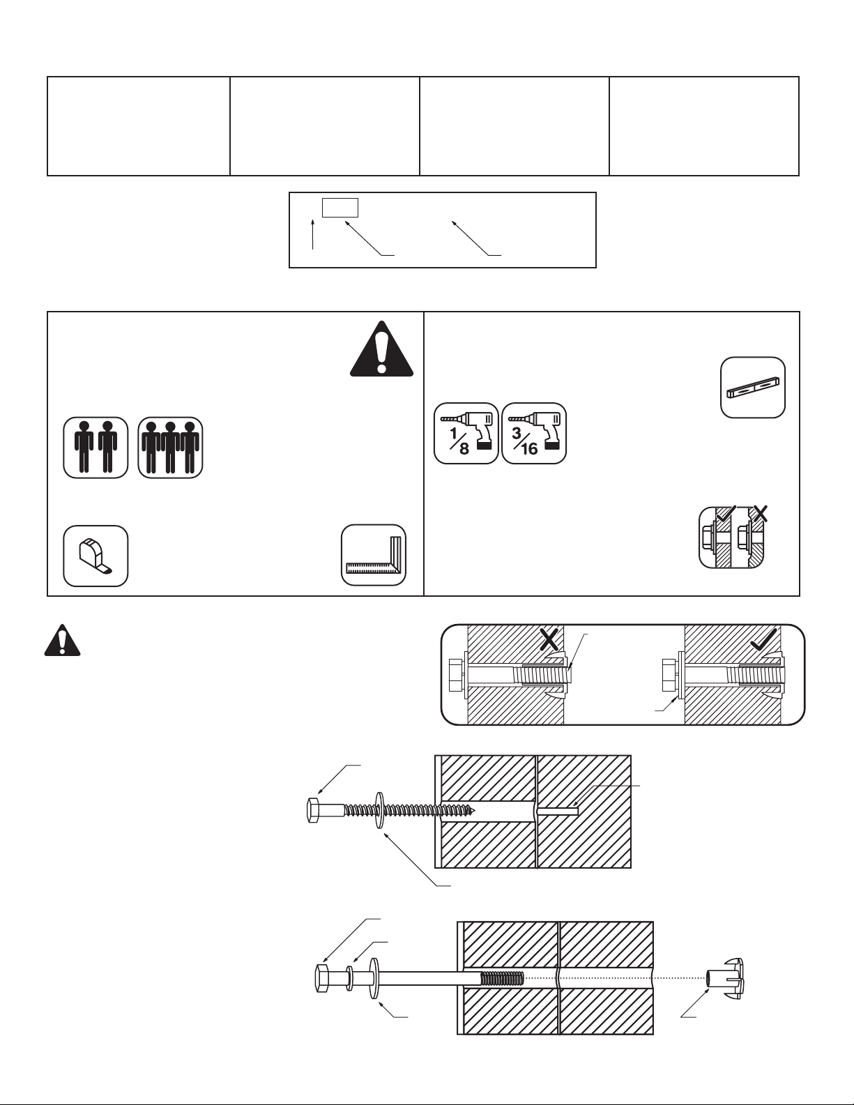
Tools Required
Keys to Assembly Success
• Tape Measure
• Carpenters Level
• Carpenters Square
• Claw Hammer
• Standard or Cordless Drill
Part Identification Key
On each page, you will find the parts
and quantities required to complete the
assembly step illustrated on that page.
Here is a sample.
• #1 Phillips, #2 Robertson
and Screwdriver
• Ratchet with extension
(1/2” & 9/16” sockets)
• Open End Wrench
(1/2” & 9/16”)
• Adjustable Wrench
• 1/8” & 3/16” Drill Bits
2X 012 Post 2 x 4 x 83”
Quantity Key Number
Part Description,
Part Size
• 3/16” Hex Key
• 8’ Step Ladder
• Safety Glasses
• Adult Helpers
• Pencil
Key Number: The first two digits
represent the step number. The third
digit represents the piece. Note that if
the part is used in multiple steps then
the number only reflects the first step it
is used in.
Symbols
Throughout these instructions symbols are provided as important reminders for proper and safe assembly.
This identifies information that requires special
attention. Improper assembly could lead to an unsafe
or dangerous condition.
Use
Help
Measure
Distance
Use
Help
Check that assembly is square
before tightening bolts.
Use a measuring tape to assure
proper location.
Where this is shown, 2 or 3 people
are required to safely complete the
step. To avoid injury or damage
to the assembly make sure to get
help!
Square
Assembly
Check that set or assembly is properly level
before proceeding.
Pre-drill 1/8” & 3/16” Bit
Pre-drill a pilot hole
before fastening screw
or lag to prevent
splitting of wood.
This indicates time to tighten bolts, but
not too tight! Do not crush the wood.
This may create splinters and cause
structural damage.
Use
Level
Tighten
Bolts
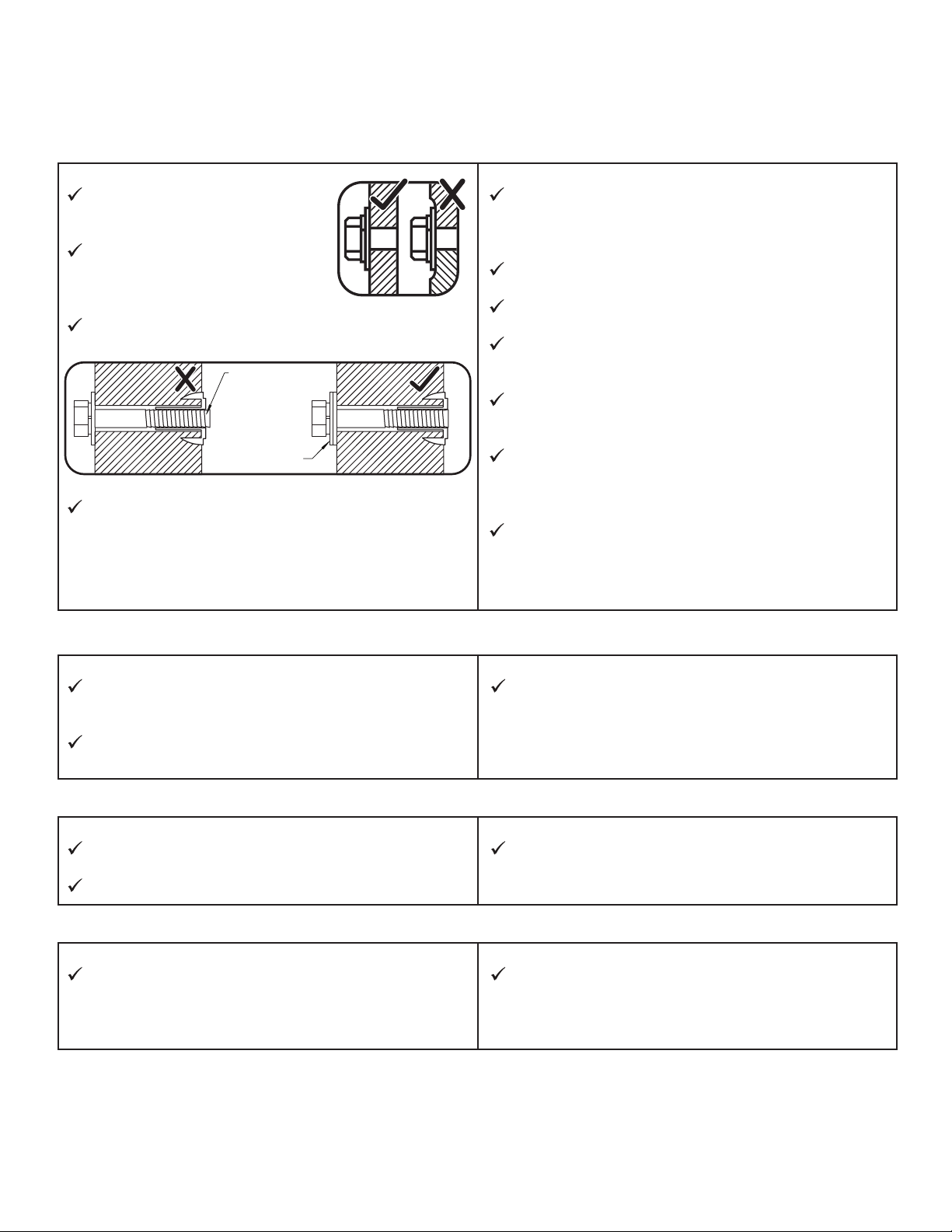
CAUTION – Protrusion Hazard
Once the assembly is tightened, watch for exposed threads.
If a thread protrudes from the T-Nut, remove
the bolt and add washers to eliminate this condition.
Extra washers have been provided for this purpose.
Proper Hardware Assembly
Lag screws require drilling pilot
holes to avoid splitting wood. Only
a flat washer is required. For ease of
installation liquid soap can be used
on all lag-type screws.
For bolts, tap T-Nut into hole with
hammer. Insert the hex bolt through
lock washer first then flat washer then
hole. Because the assemblies need to
be squared do not completely tighten
until instructed. Pay close attention to
diameter of the bolts. 5/16” is slightly
larger than 1/4”.
Note: Wafer head bolts with blue lock
tight or a bolt with a Ny-Lok nut do
NOT require a lock washer.
Lag Screw
Hex Bolt
Lock
Washer
Flat
Washer
No Yes
If Bolt protrudes
beyond T-Nut
Use an extra
flat washer
Lag Assembly
Before mounting Lag
Screw, use factory drilled
holes as guides to drill 1/8”
pilot holes
Flat Washer
Bolt Assembly
T-Nut
(Hammer into place)
Do not crush wood!
6

Your Key To Quick Assembly
SORTING WOOD PARTS INTO
EACH ASSEMBLY STEP WILL
SAVE TIME!
Step Step Step
SAVE TIME - TIP #1:
Wood parts are found in Box 2, 3, 4 & 5. Open each box with wood parts and
look for the Key Number stamped on the end of the wood part (see chart below).
Sort each wood part into the different assembly steps.
2X 012 Post 2 x 4 x 83”
Part Quantity Key Number
Step Number
(This is Step 1)
01 2
Order Listed
(The order the part is
SAVE TIME - TIP #2:
In addition to the key number stamp, you can also identify the wood parts by
using the Parts Identication pages in the manual or the Parts Identication
weather resistant poster.
Part Description Part Size
Key Number: The rst two digits represent the step
number. The third digit represents the order in which
the part is listed in the step.
listed in step 1)
Note that if the part is used in multiple steps then
the key number only reects the rst step it is used in.
.
HARDWARE:
The majority of each hardware part comes packed in a separate bag so
you do not need to sort the hardware. Each assembly step indicates which
hardware (bolt, screw, washer etc.) you will require to complete the step.
7
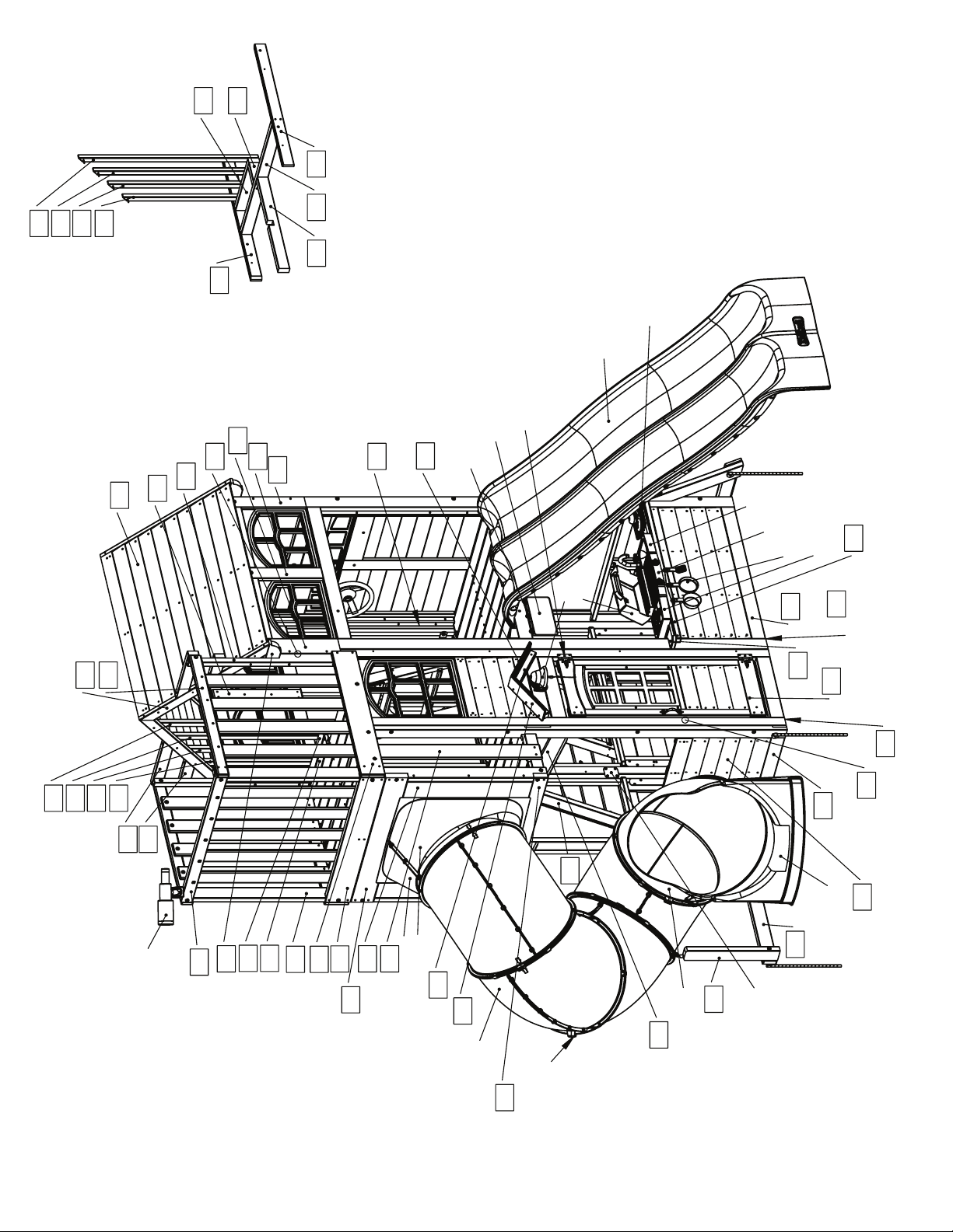
9x TNR 2 Slide Elbow
TNR 4 Clamp Ring Set (10Pk)
Flat Panel Bracket Set (4Pk)
FRONT
420
421
422
423
Front Roof Panel FSC
311
x2
325
x2
381
054
053
(hidden)
x2
391
055
x2
323
x2
324
x2
322
052
051
252
(Swing
hidden)
x2
341
443
Door Hardware
Sign
Utensil Shelf x2
Fruit & Basket
Double Ride Maze N Wave Slide
Sink
BBQ Base
BBQ Utensils
Cooktop
131
420
x4
301
421
422
x2
411
423
4132x412
2x
Telescope w/ Mount
225
371
2x
294
295
221
2x
233
224
223
261
262
2x
2x
TNR 2 Slide LT Flange
442
2x
441
TNR 2 Slide RT Flange
Bell
024
BBQ Lid
227
571
072
Wall FSC
Panel Front
132
570
081
(hidden)
2x
161
Panel FSC
Door Window
162
060
End Panel FSC
(hidden)
061
End Half Wall FSC
TNR 3 Short Exit
063
Narrow Front Panel FSC
TNR 2 Slide Exit Top
222
8
x2
Heavy "C" Bracket
Heavy "L" Bracket x3
Crow Ladder Grip
292
291
231
(hidden)
x2
x3
232
043
041
x2
044
(hidden)
251
x2
226
2x Steel
Hand Grips
(hidden)
TNR 4 Post Mount
(hidden)
TNR Tube Support
414
13x
(hidden)
Bracket (3Pk)
Narrow Angle
Back Roof Panel FSC
312
321
2x
331
332
2x
172
042
112
082
2x
Plaque
KK Playset
271
228
113
031
x18
111
032
061
025
033
033
023
032
121
033
142
032
123
033
030
062
Back Panel Narrow FSC
033
Rocks (18Pk)
030
x4
022
122
141
(hidden)
020
EN71 Hand Rail
151
021
073
Panel FSC
Wakll Back
071
Swing Wall Panel FSC
Panel Corner Bracket (8Pk)
Flat Bracket (2Pk)
Corner Bracket (9Pk)
Swing Belt Seat x2
Swing Rope x4
Plastic Formed
BACK
Heavy Flat Bracket x2
2x MOD 5 Pane Window (2Pk)
Washers (18Pk)
Acro Rope x2
171
Quick Links x6
Spring Loaded
DX Swing Hanger (6Pk)
Acro Bar
Acro Handle x2
181
182
191
Stake (6Pk)
183
Rebar Ground
2x
9
Part Identification (Reduced Part Size)
Part Identification (Reduced Part Size)
Part Identification (Reduced Part Size)
Part Identification (Reduced Part Size)
2pc. -044 - 15.9 x 82.6 x 482.6mm - Nest Ladder Gap FSC - Box 3 - 4819234
5/8 x 3-1/4 x 19"
1pc. -023 - 15.9 x 82.6 x 533.4mm - Ladder Gap FSC - Box 3 - 4818958
5/8 x 3-1/4 x 21"
1pc. -
292
- 15.9 x 82.5 x 971.5 - Crowsnest Floor Long Gap FSC - Box 3 - 4819315
5/8 x 3-1/4 x 38-1/4"
1pc. -025 - 15.9 x 82.6 x 1060.5 mm - RW-AL Support FSC - Box 3 - 4819263
5/8 x 3-1/4 x 41-3/4"
1pc. -453 - 15.9 x 85.7 x 285.8 mm - Bell Top RT FSC - Box 3 -
5/8 x 3-3/8 x 11-1/4"
1pc. -451 - 15.9 x 85.7 x 285.8 mm - Bell Top FSC - Box 3 - 4609102
5/8 x 3-3/8 x 11-1/4"
1pc. -294 - 15.9 x 85.7 x 398.5mm - Short Floor Gap FSC - Box 3 - 4819264
5/8 x 3-3/8 x 15-11/16"
1pc. -295 - 15.9 x 85.7 x 398.5mm - Short Floor FSC - Box 3 - 4819265
5/8 x 3-3/8 x 15-11/16"
13pc. -414 - 15.9 x 85.7 x 827.1mm - Cedar Wall FSC - Box 3 - 4819308
1pc. -113 - 15.9 x 85.7 x 904.9mm - Floor Board FSC - Box 3 - 4819050
2pc. -
261
- 15.9 x 101.6 x 923.8 - Wall Board FSC - Box 2 - 4819313
4609101
5/8 x 3-3/8 x 32-9/16"
5/8 x 3-3/8 x 35-5/8"
5/8 x 4 x 36-3/8"
1pc. -
031
- 15.9 x 108 x 562mm - Access Board FSC - Box 3 - 4819032
5/8 x 4-1/4 x 22-1/8"
18pc. -111 - 15.9 x 114.3 x 904.9mm - Floor Board FSC - Box 2 - 4819051
5/8 x 4-1/2 x 35-5/8"
1pc. -271 - 15.9 x 114.3 x 904.9mm - Crowsnest Front Gap FSC - Box 3 - 4819291
5/8 x 4-1/2 x 35-5/8"
2pc. -291 - 15.9 x 114.3 x 971.5mm - Crowsnest Floor Long FSC - Box 3 - 4819314
5/8 x 4-1/2 x 38-1/4"
10
Part Identification (Reduced Part Size)
Part Identification (Reduced Part Size)
Part Identification (Reduced Part Size)
Part Identification (Reduced Part Size)
2pc. -
030
- 15.9 x 133.4 x 562mm - Access Rock Bottom FSC - Box 3 - 4818515
5/8 x 5-1/4 x 22-1/8"
3pc. -
032
- 15.9 x 133.4 x 562mm - Rock Board A FSC- Box 3 - 4818511
5/8 x 5-1/4 x 22-1/8"
5pc. -
033
- 15.9 x 133.4 x 562mm - Board Rock B FSC - Box 3 - 4818512
5/8 x 5-1/4 x 22-1/8"
1pc. -
123
- 23.8 x 57.2 x 482.6mm - Small Half Wall Top FSC - Box 2 -
15/16 x 2-3/8 x 19"
1pc. -
121
- 23.8 x 57.2 x 850.9mm - SW Wall Top FSC - Box 3 - 4819071
1pc. -122 - 23.8 x 57.2 x 990.6mm - Half Wall Top FSC - Box 2 - 4819131
4819323
15/16 x 2-3/8 x 33-1/2"
15/16 x 2-1/4 x 39"
2pc. -411 - 23.8 x 63.5 x 857.3 - Crowsnest Top Side FSC - Box 2 - 4819309
15/16 x 2-1/2 x 33-3/4"
2pc. -391 - 23.8 x 76.2 x 435mm - Short Wall Tie FSC - Box 2 - 4819266
15/16 x 3 x 17-1/8"
2pc. -325 - 23.8 x 76.2 x 489mm - Wall Tie FSC - Box 3 - 4819117
15/16 x 3 x 19-1/4"
1pc. -
141
- 23.8 x 82.6 x 362 mm - SW Ground FSC - Box 3 - 4812606
15/16 x 3-1/4 x 14-1/4"
3pc. -043 - 23.8 x 82.6 x 444.5mm - Nest Tread FSC - Box 2 - 4819243
15/16 x 3-1/4 x 17-1/2"
4pc. -
022
- 23.8 x 82.6 x 495.3 mm - Tread FSC - Box 3 - 4818957
15/16 x 3-1/4 x 19-1/2"
1pc. -151 - 23.8 x 82.6 x 601.7mm - Support Diagonal FSC - Box 2 - 4819269
15/16 x 3-1/4 x 23-11/16"
1pc. -132 - 23.8 x 108 x 1086.5mm - Table Top FSC - Box 2 - 4819324
15/16 x 4-1/4 x 42-3/4"
1pc. -233 - 23.8 x 133.4 x 889mm - Crowsnest Bottom Side Front FSC - Box 2 - 4819307
15/16 x 5-1/4 x 35"
11
Part Identification (Reduced Part Size)
Part Identification (Reduced Part Size)
Part Identification (Reduced Part Size)
Part Identification (Reduced Part Size)
1pc. -231 - 23.8 x 133.4 x 889mm - Crowsnest Bottom Side Back FSC - Box 2 - 4819306
15/16 x 5-1/4 x 35"
1pc. -423 - 25.4 x 31.8 x 686.2mm - Angle Wall D FSC - Box 2 - 4819319
1pc. -422 - 25.4 x 31.8 x 786.7mm - Angle Wall C FSC - Box 2 - 4819320
1pc. -421 - 25.4 x 31.8 x 887.2mm - Angle Wall B FSC - Box 2 - 4819321
1pc. -420 - 25.4 x 31.8 x 987.7mm - Angle Wall A FSC - Box 2 - 4819322
1pc. -052 - 25.4 x 60.3 x 865mm - Front Wall Tie FSC - Box 2 - 4819302
1pc. -053 - 25.4 x 60.3 x 865mm - Back Wall Tie FSC - Box 1 - 4819303
1pc. -162 - 25.4 x 63.5 x 254mm - Door Stop FSC - Box 2 - 4812715
1 x 2-1/2 x 10"
4pc. -
301
- 31.8 x 57.2 x 838.20mm - Roof Support FSC - Box 2 - 4609105
1pc. -
055
- 31.8 x 60.3 x 139.7mm - Ladder Joist Side FSC - Box 3 - 4819296
1-1/4 x 2-3/8 x 5-1/2"
2pc. -412 - 31.8 x 60.3 x 170.5mm - Short Roof Tie FSC - Box 3 - 4819318
1-1/4 x 2-3/8 x 6-3/4"
1 x 1-1/4 x 27"
1 x 1-1/4 x 30-31/32"
1 x 1-1/4 x 34-15/16"
1 x 2-3/8 x 34-1/16"
1 x 2-3/8 x 34-1/16"
1-1/4 x 2-1/4 x 33"
1 x 1-1/4 x 38-7/8"
2pc. -232 - 31.8 x 60.3 x 266.7mm - Wall Board Support FSC - Box 2 - 4819312
1-1/4 x 2-3/8 x 10-1/2"
2pc. -413 - 31.8 x 60.3 x 340.8mm - Roof Tie FSC - Box 3 - 4819260
1-1/4 x 2-3/8 x 13-13/32"
1pc. -054 - 31.8 x 60.3 x 374.7mm - Nest Joist Back FSC - Box 3 - 4819294
1-1/4 x 2-3/8 x 14-3/4"
1pc. -252 - 31.8 x 60.3 x 654mm - Nest Joist Center FSC - Box 2 - 4819295
1-1/4 x 2-3/8 x 25-3/4"
1pc. -051 - 31.8 x 60.3 x 857.3mm - Nest Joist Mid FSC - Box 2 - 4819297
1-1/4 x 2-3/8 x 33-3/4"
2pc. -226 - 31.8 x 63.5 x 311.2mm - Crowsnest Side Joist FSC - Box 3 - 4819298
1-1/4 x 2-1/2 x 12-1/4"
2pc. -332 - 31.8 x 63.5 x 419.1mm - Swing Side Upright FSC - Box 2 - 4819112
1-1/4 x 2-1/2 x 16-1/2"
2pc. -381 - 31.8 x 63.5 x 844.6mm - Wall Post FSC - Box 2 - 4819316
1-1/4 x 2-1/2 x 33-1/4"
1pc. -225 - 31.8 x 63.5 x 971.5mm - Barrier Top End FSC - Box 2 - 4819305
1-1/4 x 2-1/2 x 38-1/4"
12
Part Identification (Reduced Part Size)
Part Identification (Reduced Part Size)
Part Identification (Reduced Part Size)
Part Identification (Reduced Part Size)
2pc. -321 - 31.8 x 63.5 x 1124mm - TB Support FSC - Box 2 - 4819114
2pc. -371 - 31.8 x 76.2 x 138.7mm - Swing Top Small FSC - Box 3 - 4819270
1-1/4 x 3 x 5-15/32"
1pc. -251 - 31.8 x 76.2 x 311.2mm - Short Joist FSC - Box 3 - 4819326
1-1/4 x 3 x 12-1/4"
2pc. -324 - 31.8 x 76.2 x 419.1mm - Center Upright FSC - Box 2 - 4819106
1-1/4 x 3 x 16-1/2"
2pc. -322 - 31.8 x 76.2 x 419.1mm - Right Upright FSC - Box 3 - 4819110
1-1/4 x 3 x 16-1/2"
1pc. -
571
- 31.8 x 76.2 x 514.4mm - TNR Upright FSC - Box 3 - 4818965
1-1/4 x 3 x 20-1/4"
1pc. -
142
- 31.8 x 76.2 x 558.8mm - Diagonal FSC - Box 3 - 4812607
1-1/4 x 3 x 22"
1-1/4 x 2-1/2 x 44-1/4"
1pc. -570 - 31.8 x 76.2 x 819.2mm - TNR Ground Brace FSC - Box 3 - 4818963
1-1/4 x 3 x 32-1/4"
2pc. -
081
- 31.8 x 76.2 x 1035.1mm - Floor Joist FSC - Box 3 - 4812608
1-1/4 x 3 x 40-3/4"
1pc. -331 - 31.8 x 76.2 x 1187.5mm - Swing Top FSC - Box 3 - 4819113
1pc. -
112
- 31.8 x 76.2 x 1606.6 - Long Floor Joist FSC - Box 2 - 4819056
2pc. -
221
- 31.8 x 76.2 x 1816.1 - Crowsnest Post FSC - Box 3 - 4819304
1pc. -222 - 31.8 x 79.4 x 971.5mm - Crowsnest Front FSC - Box 2 - 4819299
1-1/4 x 3-1/8 x 38-1/4"
1pc. -228 - 31.8 x 88.9 x 391mm - Crowsnest Gusset Back FSC - Box 2 - 4819310
1-1/4 x 3-1/2 x 15-25/64"
1pc. -227 - 31.8 x 88.9 x 418.5mm - Crowsnest Gusset Front FSC - Box 2 - 4819311
1-1/4 x 3 x 46-3/4"
1-1/4 x 3 x 63-1/4"
1-1/4 x 3 x 71-1/2"
1-1/4 x 3-1/2 x 16-1/2"
2pc. -323 - 31.8 x 108 x 419.1mm - Left Upright FSC - Box 3 - 4819107
1-1/4 x 4-1/4 x 16-1/2"
1pc. -
223
- 31.8 x 123.7 x 971.5 - Crowsnest Slide Top FSC - Box 1 - 4819300
1-1/4 x 4-7/8 x 38-1/4"
13
Part Identification (Reduced Part Size)
Part Identification (Reduced Part Size)
Part Identification (Reduced Part Size)
Part Identification (Reduced Part Size)
2pc. -262 - 31.8 x 128 x 684.3mm - Crowsnest Front Spacer FSC - Box 2 - 4819293
1-1/4 x 5-1/32 x 26-15/16"
1pc. -
224
- 31.8 x 139.8 x 971.5 - Crowsnest Bottom End FSC - Box 3 - 4819301
1pc. -041 - 34.9 x 63.5 x 1045.2mm - Nest Right Access FSC - Box 1 - 4819236
1pc. -042 - 34.9 x 63.5 x 1045.2mm - Nest Left Access FSC - Box 1 - 4819237
1pc. -
024
- 34.9 x 63.5 x 1468.8mm - Rock Rail FSC - Box 3 - 4819058
1-1/4 x 5-1/2 x 38-1/4"
1-3/8 x 2-1/2 x 41-1/8"
1-3/8 x 2-1/2 x 41-1/8"
1-3/8 x 2-1/2 x 57-53/64"
1pc. -021 - 34.9 x 63.5 x 1468.8mm - Left Access FSC - Box 3 -
1pc. -020 - 34.9 x 63.5 x 1468.8mm - Right Access FSC - Box 3 -
2pc. -
452
- 38.1 x 38.1 x 269.9mm - Bell Support FSC - Box 2 1-1/2 x 1-1/2 x 10-5/8"
1pc. -
131
- 38.1 x 38.1 x 1006.5mm - Table Support FSC - Box 3 - 4812612
2pc. -
341
- 38.1 x 38.1 x 1409.7 - Wall Support FSC - Box 1 - 4819118
2pc. -
082
- 38.1 x 38.1 x 1600 - Side Joist FSC - Box 1 - 4819064
1pc. -
181
- 63.5 x 76.2 x 381 - SW Block Angle FSC - Box 3 -
2-1/2 x 3 x 15"
1pc. -
182
- 63.5 x 76.2 x 381 SW Block FSC - Box 3 - 4818507
2-1/2 x 3 x 15"
1pc. -
172
- 76.2 x 76.2 x 406.4 - SW Mount FSC - Box 3 - 4819069
3 x 3 x 16"
4819054
4609100
4819068
1-3/8 x 2-1/2 x 57-53/64"
4819055
1-1/2 x 1-1/2 x 39-5/8"
1-1/2 x 1-1/2 x 63"
1-3/8 x 2-1/2 x 57-53/64"
1-1/2 x 1-1/2 x 55-1/2"
1pc. -
191
- 63.5 x 76.2 x 1295.4 - Support Cross FSC - Box 1 - 4819067
2-1/2 x 3 x 51"
2pc. -
183
- 76.2 x 76.2 x 2336.8mm - SW Post FSC - Box 1 - 4819070
3 x 3 x 92"
1pc. -
171
- 76.2 x 133.4 x 2336.8 - Engineered SW Beam FSC - Box 1 - 4819049
14
3 x 5-1/4 x 92"
Part Identification (Reduced Part Size)
Part Identification (Reduced Part Size)
Part Identification (Reduced Part Size)
Part Identification (Reduced Part Size)
1pc. -
073
- 31.8 x 1092.2 x 2336.8mm
Wall Back Panel FSC - Box 2 - 47819203
1-1/4 x 43 x 92"
1pc. -
072
- 31.8 x 1092.2 x 2336.8mm
Panel Front Wall FSC - Box 2 - 47819135
1-1/4 x 43 x 92"
Narrow Front Panel FSC - Box 2 - 47819144
1pc. -
071
- 31.8 x 939.8 x 2336.8mm
SW Wall Panel FSC - Box 3 - 47819150
1-1/4 x 37 x 92"
1pc. -
063
- 31.8 x 546.1 x 2336.8mm
1-1/4 x 21-1/2 x 92"
1pc. -
060
- 31.8 x 939.8 x 2336.8mm
End Panel FSC - Box 3 - 47819200
1-1/4 x 37 x 92"
1pc. -
062
- 31.8 x 546.1 x 2336.8mm
Back Panel Narrow FSC - Box 2 - 47819193
1-1/4 x 21-1/2 x 92"
15
Part Identification (Reduced Part Size)
Part Identification (Reduced Part Size)
Part Identification (Reduced Part Size)
Part Identification (Reduced Part Size)
1pc. -
061
- 31.8 x 514.4 x 809.6mm
End Half Wall FSC - Box 3 - 47819201
1-1/4 x 20-1/4 x 31-7/8"
1pc. -
311
- 31.8 x 825.5 x 1143 mm
Front Roof Panel FSC - Box 3 - 47609082
1-1/4 x 32-1/2 x 45"
1pc. -
161
- 31.8 x 400.1 x 1070mm
Door Window Panel FSC - Box 2 - 47602837
1-1/4 x 15-3/4 x 42-1/8"
1pc. -
312
- 31.8 x 819.2 x 1143 mm
Back Roof Panel FSC - Box 3 - 47609124
1-1/4 x 32-1/4 x 45"
1x
- TNR3 Short Exit
(3310132)
1x
- TNR 2 Slide Exit Top
(3310124)
1x
- TNR 2 Slide Rt Flange
(3310123)
1x
- TNR 2 Slide Lt Flange
(3310122)
1x
- TNR 4 Clamp Ring Set
(3300130) (10 Pk)
9x
- TNR 2 Slide Elbow
(3310121)
16
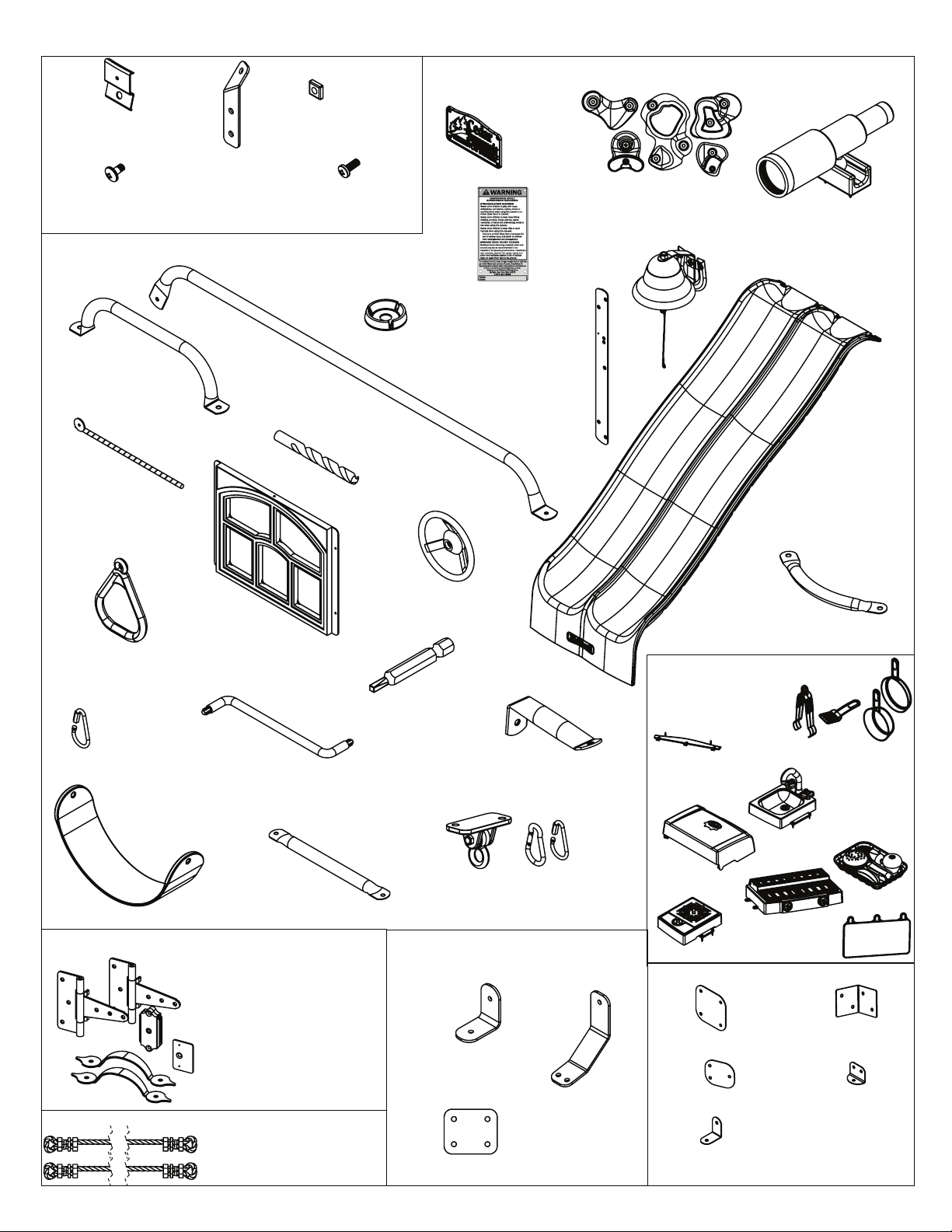
Part Identification
2x
- TNR 4 Post Mount
Clamp
(9200157)
30x
- 1/4 x 12.7mm Pan
Head Bolt
(53453202)
2x
- Steel Hand Grip
(9200211) -Yellow
1x
- Rebar Ground
Stake (6 Pk)
(3200318)
1x
- TNR 4 Post Mount
1x
- TNR 4 Post Mount
2x
31x
Base
(9200156)
(3200155)
1x
- EN71 Hand Rail (3200224) -Yellow
1x
- MOD 5 Pane Window
(2Pk) (3330502)
(Reduced Part Size)
1x
- Cedar
- Square Nylok Nut
(54902200)
1x
- 1/4 x 14.5mm Pan
Head Bolt
(53452209)
1x
- Plastic Formed
Washer (18 Pk)
(3290000)
- 3/8" Drill Bit
1x
Summit/KidKraft
Plaque
(9320358)
1x
- KK Playset
Plaque
(9320370)
1x - Flange Mount
(2pk)
- Steering Wheel
(3320255)
(3325996)
1x
- Rocks (8pk) (3320013)
1x
- Bell with Horseshoe
(3200309)
- Double Ride Maze N Wave Slide (3318125)
1x
1x
- Telescope w/ Mount
(3320161)
1x
- Crow Ladder
Grip
(9200235)
2x
- Acro Handle
(9200131)
1x
- Quick Links w.
Thread (2pk)
(3200022)
1x
- Quadrex Driver
(9200015)
2x
- Swing Belt Seat
(9320130)
1x
- Door Hardware (3200710)
2x 9207712
Door Hinge
9207713
Door Catch
1x Magnetic Catch
1x Catch Plate
2x 9207711
Door Handle
1x
- Crimp Rope Bag (3502045)
Robertson Driver
1x
- Acro Bar
(9200131)
2x Acro Rope EN71
4x Swing Rope w/ Crimps
1x
- #2 x 2"
(9200014)
1x
- DX Swing Hangers
with Quick Links (6 Pk)
1x
3x
- Heavy L-Bracket
(9200151)
2x
- Heavy Flat Bracket
(9200149)
1x
- TNR3 Tube Support
(9200158)
(3201950)
- Heavy Bracket Set
(3205701)
1x
- Heavy C-Bracket
(9200153)
1x
- BBQ Deluxe Kitchen
Set (3330008)
2x
- Utensil Shelf
9321691
1x
- BBQ Sink Set
3332608
1x
- BBQ Lid
9327812
1x - BBQ Base
3331611
1x - BBQ Cooktop 3332609
1x
- Playset Bracket Set (3205955)
1x
- Flat Panel Bracket
1x
(4 Pk)(3205941
1x
- Flat Bracket (2 Pk)
(3205960)
1x
- Narrow Angle
Bracket (3 Pk)
(3205940)
1x
- BBQ Utensils
3331610
1x
- Basket with
Fruit 3330015
1x
- Sign
9331614
- Corner Panel
Bracket (6 Pk)
(3205977)
1x
- Corner
Bracket (3 Pk)
(3205973)
17
Hardware Identification
(10)
LW2 - 5/16" Lock Washer - (51303300)
(58)
LW1 - 1/4" Lock Washer - (51303200)
(Actual Size)
(18)
FW0 - 3/16" Flat Washer -
(51103100)
(52)
FW1 - 1/4" Flat Washer - (51103200)
(8) FW6 - #12 Screw Bezel - (9299500)
-
(40)
TN1
- 1/4" T - Nut
(54503200)
(67)
LN1
(18)
LN2
(7) LN3 -
(10)
S40
(56)
PB1 - Pan Bolt
1/4 Lock Nut
-
- 5/16" Lock Nut
3/8 Lock Nut
- Truss Screw
- (54303200)
-
- (54303800)
#6 x 3/4"
1/4 x 3/4"
(54303300)
- (52933903)
- (53453203)
(66)
FW2 - 5/16" Flat Washer - (51103300)
(14)
FW10 - 3/8" Flat Washer - (51103800)
(66) S0
- Truss Screw
(25)
(17)
#8 x 7/8"
TN2
- 5/16" T- Nut
BN1
- 1/4" Barrel Nut
- (52933505)
-
(54503300)
-
(54803200)
(12)
PB6 - Pan Bolt
(32)
S37 - Pan Screw
(3)
S10 - Pan Screw
(34) S8
(19) S6
(29) S7
- Pan Screw
- Pan Screw
- Pan Screw
1/4 x 1"
#7 x 5/8"
#8 x 1"
#12 x 3/4"
#12 x 1"
#12 x 2"
- (53413210)
- (52433009)
- (52433510)
- (52433603)
- (52433610)
- (52433620)
(17)
PB2 - Pan Bolt
(9)
S38 - Pan Screw
(246)
S20 - Wood Screw
(9) S2
(118) S3
(22) S4
- Wood Screw
(88)
S11 - Wood Screw
- Wood Screw
- Wood Screw
1/4 x 1-1/4"
#7 x 1-1/8"
#8 x 1-3/8"
#8 x 1-1/2"
#8 x 2"
#8 x 2-1/2"
#8 x 3"
- (52043530)
- (53433212)
- (52433014)
- (52043516)
- (52043512)
- (52043520)
- (52043522)
18
Hardware Identification
(Actual Size)
(7)
WB7 -
(8) WL3 - Wafer Lag
(52613216)
(19)
(1)
LS1 - Lag Screw
(1) H8
(5)
Wafer Bolt 5/16 x 3"
WL5 - Wafer Lag
1/4 x 1-1/2"
Hex Bolt 1/4 x 4-1/4"
-
LS9 - Lag Screw
1/4 x 1-3/8"
1/4 x 2-1/2"
5/16 x 4-3/4"
- (53613330)
- (52613222)
- (52213212)
- (53703241)
- (52213343)
(6)
WB9 -
(2)
WB8 -
(6) WB10 -
(6)
H10 -
(2) H3
(8) H1
Wafer Bolt 5/16 x 2-1/8"
Wafer Bolt 5/16 x 2-3/8"
Wafer Bolt 5/16 x 2-5/8"
Hex Bolt 1/4 x 2-1/4"
Hex Bolt 1/4 x 2-1/2"
-
Hex Bolt 1/4 x 1-1/2"
-
- (53703221)
- (53613324)
- (53613326)
- (53613329)
- (53703222)
- (53703212)
(6)
G21 -
(2) G5 -
(12)
G13 -
(1)
G20 -
(4)
G17 -
Hex Bolt 5/16 x 3-3/4"
Hex Bolt 5/16 x 4-1/2"
Hex Bolt 5/16 x 6-1/8"
Hex Bolt 3/8 x 4"
Hex Bolt 3/8 x 6"
- (53703840)
- (53703860)
- (53703333)
- (53703342)
- (53703364)
(10)
Hex Bolt 1/4 x 3"
H12 -
(5) H2
- (53703230)
Hex Bolt 1/4 x 2"
-
(6) H9
(53703211)
Hex Bolt 1/4 x 1-1/4"
-
- (53703220)
(1)
19
Hex Bolt 3/8 x 9-1/4"
G26 -
- (53703891)
Step 1: Inventory Parts - Read This Before Starting Assembly
STOP STOPSTOP STOP
A.
This is the time for you to inventory all your hardware, wood and accessories,
referencing the parts identication sheets. This will assist you with your assembly.
• The wood pieces will have the key number stamped on the ends of the boards.
Organize the wood pieces by step, as per the key numbering system below.
2X 012 Post 2 x 4 x 83”
Quantity Key Number Part Description,
• Please refer to Page 6 for proper hardware assembly.
Part Size
Key Number: The rst two digits represent the step
number. The third digit represents the piece. Note
that if the part is used in multiple steps then the
number only reects the rst step it is used in.
• Each step indicates which bolts and/or screws you will need for assembly, as well as
any at washers, lock washers, t-nuts or lock nuts.
B. If there are any missing or damaged pieces or you need assistance with
assembly please contact the consumer relations department directly. Call us
before going back to the store.
customersupport@kidkraft.com
Online Parts Replacement:
Cedarsummitplay.com/parts-centerwarranty-claim
Customer Service:
1(800) 933-0771 or (972) 385-0100
C. Read the assembly manual completely, paying special attention to EN71 and
Europe Customer Service: +31 (0)20 305 8620
europecustomerservice@kidkraft.com
EU Online Parts Replacement: parts.kidkraft.eu
ASTM warnings; notes; and safety/maintenance information on pages 1 - 6.
D. Before you discard your cartons ll out the form below.
• The carton I.D. stamp is located on the end of each carton. The tracking number is
located on the Cedar Summit ID Plaque (9320370).
• Please retain this information for future reference. You will need this information if you
contact the Consumer Relations Department.
MODEL NUMBER: F29055E
CARTON I.D. STAMP: __ __ __ __ __ 14459 ___ (Box 1)
CARTON I.D. STAMP: __ __ __ __ __ 14459 ___ (Box 2)
CARTON I.D. STAMP: __ __ __ __ __ 14459 ___ (Box 3)
TRACKING NUMBER (from ID Plaque):
20
CARTON I.D. STAMP: __ __ __ __ __ 14459 ___ (Box 4)
CARTON I.D. STAMP: __ __ __ __ __ 14459 ___ (Box 5)
CARTON I.D. STAMP: __ __ __ __ __ 14459 ___ (Box 6)
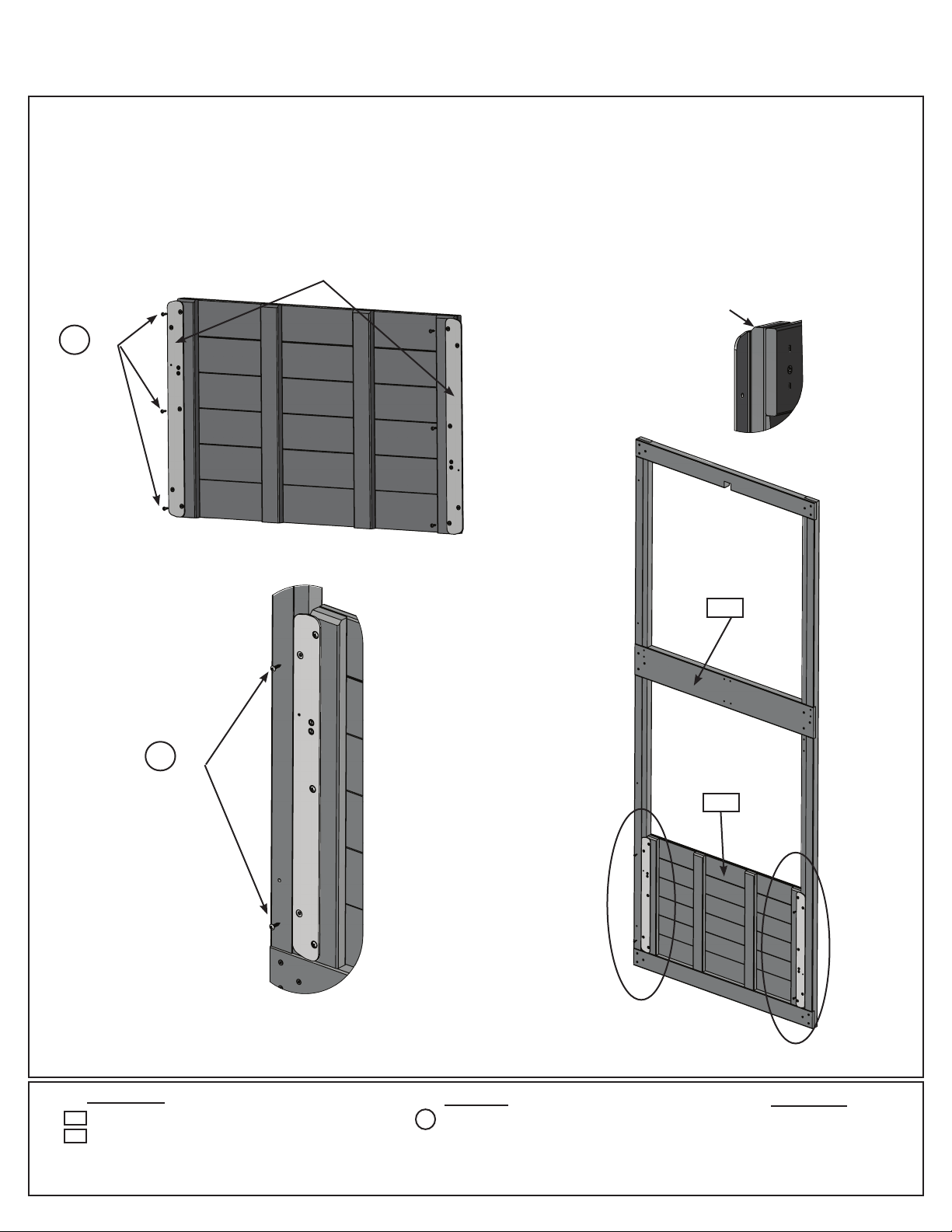
Step 2: Access Ladder / Rockwall Assembly
Part 1
A: Place (020) Right Access on one side of 4 (022) Treads and (021) Left Access on the other side with the
grooves facing in. (g. 2.1)
B: Fit each (022) Tread into grooves on both (020) and (021) Access rails, make sure the top edge of the (022)
Treads are ush to the front of the Access rails. (g. 2.1 and 2.2)
C: Pre-drill pilot holes with a 1/8” drill bit and attach rails and treads together using 4 (S3) #8 x 2-1/2” Wood
Screws per tread. (g. 2.1)
Fig. 2.1
022
S3
021
Flush to
top edge
020
S3
Fig. 2.2
End View
Flush to
edges
Wood Parts Hardware
1 x Right Access 1-3/8 x 2-1/2 x 57-53/64”
020
021
1 x Left Access 1-3/8 x 2-1/2 x 57-53/64”
022
4 x Tread 15/16 x 3-1/4 x 19-1/2”
21
022
Top Edge of Access Rail
S3
16 x #8 x 2-1/2” Wood Screw
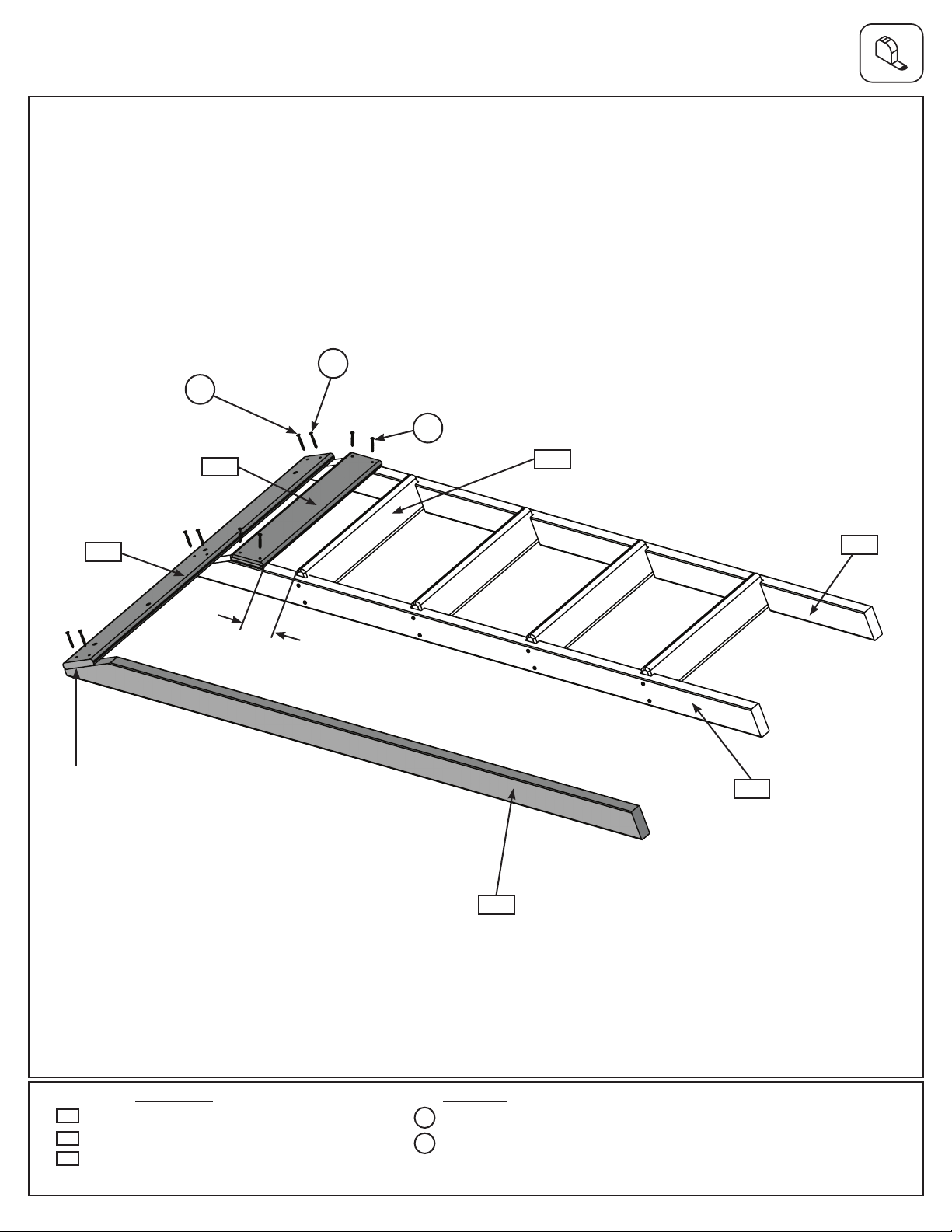
Step 2: Access Ladder / Rockwall Assembly
Part 2
D: Place (023) Ladder Gap on each access rail so there is a 2-3/8” gap between (023) Ladder Gap and the top
(022) Tread. Attach using 4 (S20) #8 x 1-3/8” Wood Screws. (g. 2.3)
E: Place (024) Rock Rail on the ground next to (020) Right Access so it matches the orientation of the two access
rails as shown in g. 2.3. Attach (025) RW-AL Support ush to the top of Access Ladder assembly and (024) Rock
Rail using 3 (S20) #8 x 1-3/8” Wood Screws in the top holes and 3 (S11) #8 x 2” Wood Screws in the bottom holes.
Pilot holes in (025) RW-AL Support should be centred over the rails. (g. 2.3)
Fig. 2.3
x 3 in bottom holes
S11
S20
x 3 in top holes
S20
x 4
Flush
025
023
2-3/8” gap between top
Tread and Ladder Gap
022
021
020
024
Wood Parts Hardware
023
1 x Ladder Gap 5/8 x 3-1/4 x 21”
1 x Rock Rail 1-3/8 x 2-1/2 x 57-53/64”
024
1 x RW-AL Support 5/8 x 3-1/4 x 41-3/4”
025
S11
3 x #8 x 2” Wood Screw
S20
7 x #8 x 1-3/8” Wood Screw
22
Step 3: Rockwall Assembly
A: Place (031) Access Board ush to the top of the Access Ladder/Rockwall Assembly and (030) Access Rock
Bottom at the bottom of the assembly as shown in g. 3.1. Then place (032) Board Rock A’s, (033) Board Rock
B’s and (030) Access Board as they are shown in g. 3.1. Do not screw boards down yet. Rock holes are to be
staggered so they do not form a straight line and are at the top of the boards. Note: Rock Boards are to be ush
to (021) Left Access Rail and pilot holes are centred over (024) Rock Rail. (g. 3.1)
B: Make sure all boards are tight together and the assembly is square, then attach all boards except for (031)
Access Board using 4 (S20) #8 x 1-3/8” Wood Screws per board. (031) Access Board to be attached in Step15
Part 2, keep aside until needed. (g. 3.1)
Fig. 3.1
Do not attach yet,
031
put aside until
Step 15
S20
x 4 per
board
Flush
IMPORTANT!
Follow hole
pattern
032
033
033
032
033
032
033
030
033
024
030
020
021
Wood Parts
030
2 x Access Rock Bottom 5/8 x 5-1/4 x 22-1/8”
031
1 x Access Board 5/8 x 4-1/4 x 22-1/8”
032
3 x Board Rock A 5/8 x 5-1/4 x 22-1/8”
033
5 x Board Rock B 5/8 x 5-1/4 x 22-1/8”
40 x #8 x 1-3/8” Wood Screw
Hardware
S20
23
Nest Access Ladder
Step 4: Nest Ladder Assembly
Nest Access Ladder
A: Place (042) Nest Left Access on one side of 3 (043 ) Treads and (041) Nest Right Access on the other side
with the grooves facing in. (g. 4.1)
B: Fit each (043) Nest Tread into grooves on both ( 041) and (042) Nest Access Rails, make sure the top edge of
the ( 043) Treads are ush to the front of the Access rails. (g. 4.1 and 4.2)
C: Pre-drill pilot holes with a 1/8” drill bit and attach rails and treads together using 4 (S3) #8 x 2-1/2” Wood
Screws per tread. (g. 4.1)
D: Place (044) Nest Ladder Gap on each access rail so there is a 2-3/8” gap between (044) Ladder Gap and the
top (043) Tread. Attach using 4 (S20) #8 x 1-3/8” Wood Screws. (g. 4.3)
E: Center a second (044) Ladder Gap between the bottom (043) Nest Tread and the bottom ends of the access
rails and attach using 4 (S20) #8 x 1-3/8” Wood Screws. (g. 4.3)
Fig. 4.1
041
Flush to
top edge
043
Fig. 4.2
End View
043
042
Fig. 4.3
S3
x 6 per
side
044
2-3/8” gap between top
Tread and Ladder Gap
Flush to
edges
S20
044
Top Edge of
Access Rail
x 2 per side
Wood Parts
042
1 x Nest Left Access 1-3/8 x 2-1/2 x 41-1/8”
041
1 x Nest Right Access 1-3/8 x 2-1/2 x 41-1/8”
043
3 x Nest Tread 15/16 x 3-1/4 x 17-1/2”
044
2 x Nest Ladder Gap 5/8 x 3-1/4 x 19”
12 x #8 x 2-1/2” Wood Screw
8 x #8 x 1-3/8” Wood Screw
Hardware
S3
S20
24
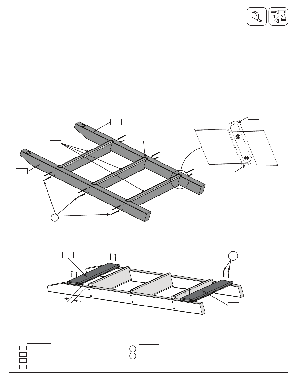
Step 5: Nest Joist Assembly
A: Place (051) Nest Joist Mid between (052) Front Wall Tie and (053) Back Wall Tie as shown in g. 5.1 making
sure to closely follow the hole orientation. Attach using 4 (S3) #8 x 2-1/2” Wood Screws.
B: Using the next set of pre-drilled holes on the (053) Back Wall Tie attach the (054) Nest Joist Back using 2 (S3)
#8 x 2-1/2” Wood Screws. (g. 5.2)
C: Place (055) Ladder Side Joist between (051) Nest Joist Mid and (054) Nest Joist Back and attach using 4
(S3) #8 x 2-1/2” Wood Screws as shown in g. 5.2.
053
Fig. 5.1
052
S3
Fig. 5.2
Note hole
orientation
051
051
S3
Note hole
orientation
053
S3
055
054
Wood Parts
051
1 x Nest Joist Mid 1-1/4 x 2-3/8 x 33-3/4”
052
1 x Front Wall Tie 1 x 2-3/8 x 34-1/16”
053
1 x Back Wall Tie 1 x 2-3/8 x 34-1/16”
054
1 x Nest Joist Back 1-1/4 x 2-3/8 x 13-5/32”
055
1 x Ladder Side Joist 1-1/4 x 2-3/8 x 5-1/2”
10 x #8 x 2-1/2” Wood Screw
Hardware
S3
25
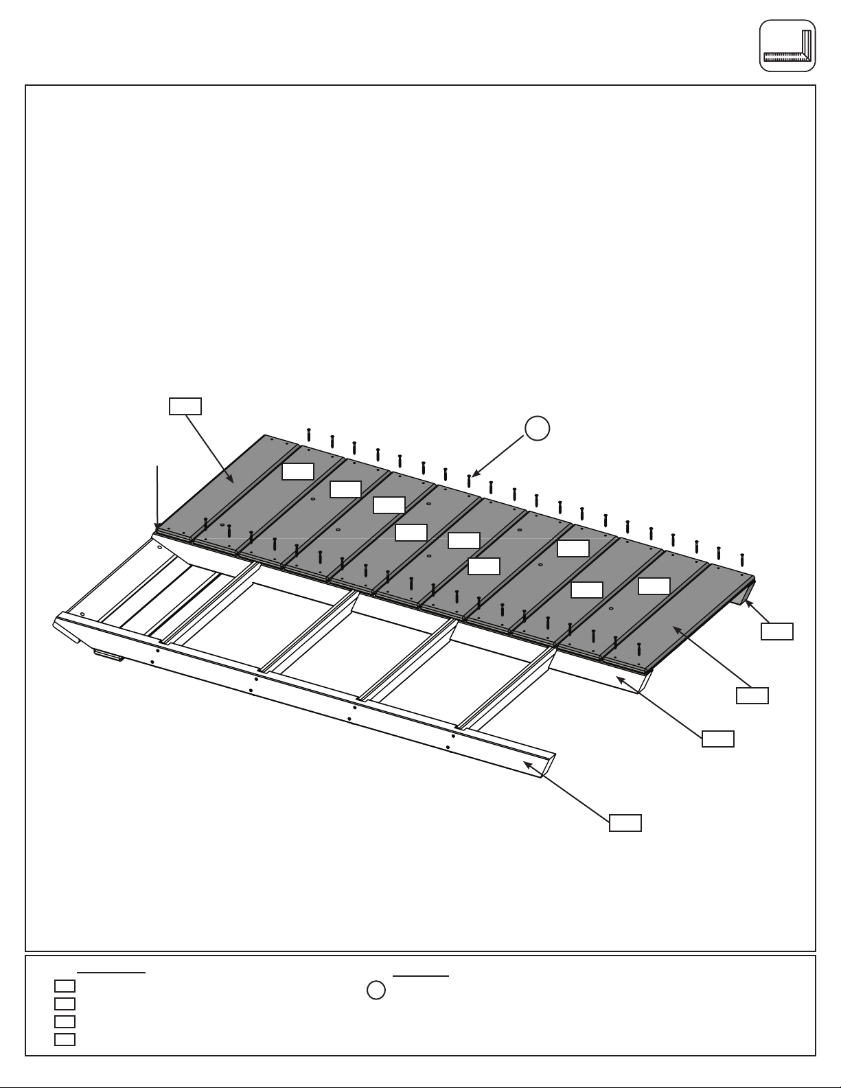
Step 6: Slide Wall Assembly
Part 1
A: Place 1 Flange 20 on each side of the End Half Wall making sure that the panel is slat side up. Check to
ensure that anges are ush at the top and bottom and attach each ange using 3 (S40) #6 x 3/4” Truss Screws
per side. g.6.1 & 6.3 & 6.4.
B: Taking note of the panel orientation, t (061) End Half Wall into the bottom of (060) End Panel as shown in
g.6.2 & 6.3 & 6.4. Attach (061) End Half Wall to (060) End Panel using 2 (S40) #6 x 3/4” Truss Screws per side.
Flange 20
Fig. 6.1
S40
x 3
per side
Fig. 6.3
Fig. 6.4
Flush
Fig. 6.2
S40
per side
060
x 2
061
Wood Parts
060
1 x End Panel 1-1/2 x 37 x 92”
061
1 x End Half Wall 1-1/4 x 20-1/4 x 31-7/8”
26
10 x #6 x 3/4” Truss Screw
S40
Hardware
Other Parts
2 x Flange 20
Step 6: Slide Wall Assembly
Part 2
A: Place (062) Narrow Panel Back against the left side of (060) End Panel noticing panel orientation. The tops
and bottoms of the panels should be ush and panels square. Pre-drill with a 3/16” drill bit, then fasten (062)
Narrow Panel Back to (060) End Panel with 4 (WL5) 1/4 x 2-1/2” Wafer Lags. (Fig. 6.5, 6.6 and 6.8)
B: Place (063) Narrow Front Panel against the right side of (060) End Panel noticing panel orientation. The tops
and bottoms of the panels should be ush and panels square. Pre-drill with a 3/16” drill bit, then fasten (060) End
Panel to (063) Narrow Front Panel with 4 (WL5) 1/4 x 2-1/2” Wafer Lags. (Fig. 6.5, 6.7 and 6.8)
Fig. 6.6
Flush
062
Notice (062) Narrow
Back Panel overlaps
(060) End Panel
WL5
060
Fig. 6.5
062
060
063
Fig. 6.7
Notice (060) End Panel
overlaps (063) Narrow
Front Panel
WL5
Flush
060
Fig. 6.8
WL5
061
Flush
Wood Parts
062
1 x Narrow Panel Back 1-1/4 x 21-1/2 x 92”
063
1 x Narrow Front Panel 1-1/4 x 21-1/2 x 92”
8 x 1/4 x 2-1/2” Wafer Lag
Hardware
WL5
27

Step 7: Swing Wall Assembly
A: Place (072) Panel Front Wall against the left side of (071) SW Wall Panel noticing panel orientation. The tops
and bottoms of the panels should be ush and panels square. Pre-drill with a 3/16” drill bit, then fasten (072)
Panel Front Wall to (071) SW Wall Panel with 4 (WL5) 1/4 x 2-1/2” Wafer Lags. (g. 7.1 and 7.2)
B: Place (073) Wall Panel Back against the right side of (071) SW Wall Panel noticing panel orientation. The
tops and bottoms of the panels should be ush and panels square. Pre-drill with a 3/16” drill bit, then fasten
(071) SW Wall Panel to (073) Wall Panel Back with 4 (WL5) 1/4 x 2-1/2” Wafer Lags. (g. 7.1 and 7.3)
Fig. 7.2
Flush
072
Notice (072) Front Wall
Panel overlaps (071)
SW Wall Panel
071
Fig. 7.1
073
Fig. 7.3
Notice (071) SW Wall
Panel overlaps (073)
Back Wall Panel
WL5
Flush
071
WL5
Wood Parts
071
1 x SW Wall Panel 1-1/2 x 37 x 92”
072
1 x Panel Front Wall 1-1/4 x 43 x 92”
073
1 x Wall Panel Back 1-1/4 x 43 x 92”
Hardware
WL5
8 x 1/4 x 2-1/2” Wafer Lag
071
Flush
28
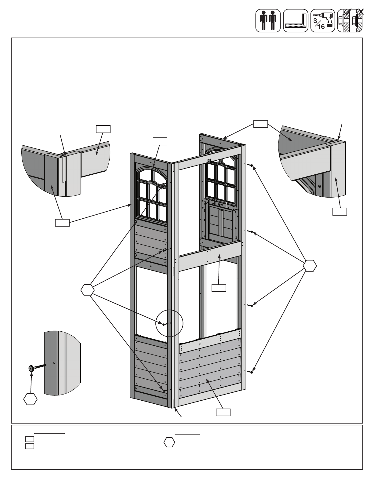
Step 8: Join Swing and Slide Assemblies
Part 1
A: With at least two helpers lift the Slide Wall Assembly and Swing Wall Assembly so the (062) Narrow Panel
Back and (063) Narrow Front Panel meet with (073) Wall Panel Back and (072) Panel Front Wall and are tight
together as shown in g. 8.1.
B: Make sure the assembly is square then on the inside of the assembly, tight to (060) End Panel and ush to
the bottom of the panels attach 1 (081) Floor Joist to (062) Narrow Panel Back and (083) Wall Panel Back and
a second (081) Floor Joist to (063) Narrow Front Panel and (072) Panel Front Wall with 4 (S7) #12 x 2” Pan
Screws per board. (g. 8.1 and 8.2)
063
Fig. 8.1
Swing Wall
Slide Wall
Assembly
Assembly
071
Fig. 8.2
060
060
062
073
072
081
062
073
Tight
(both sides)
Wood Parts Hardware
081
2 x Floor Joist 1-1/4 x 3 x 40-3/4”
29
29
Flush
S7
x 4 per board
S7
8 x #12 x 2” Pan Screw
081
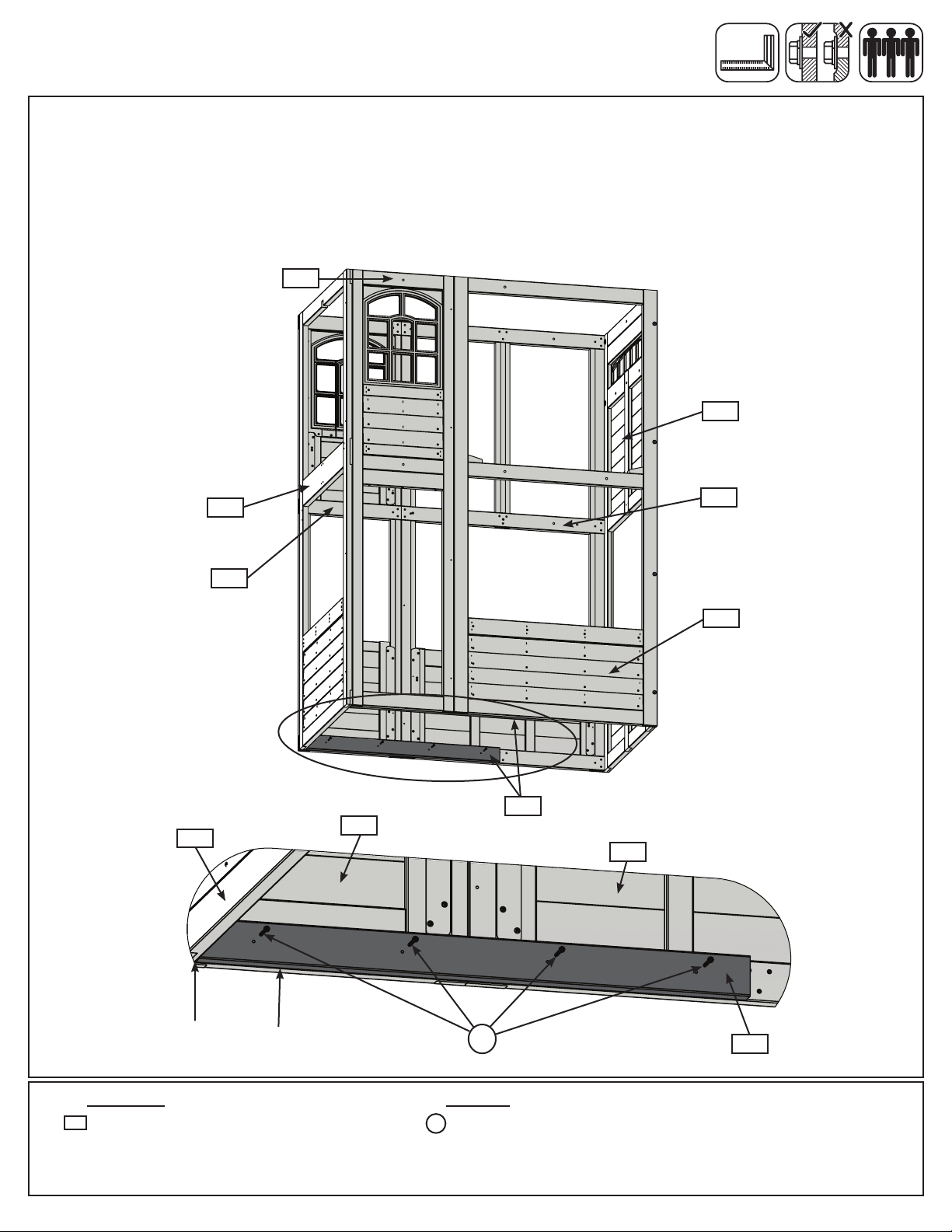
Step 8: Join Swing and Slide Assemblies
Part 2
C: From inside the assembly, tight to both (072) Front Wall Panel and (063) Narrow Front Panel, halfway up the
assembly, 5/8” below the panel, loosely attach 1 (082) Side Joist to (072) Front Wall Panel and (063) Narrow Front
Panel Back with 3 (WB10) 5/16 x 2-5/8” Wafer Bolts (with at washer and t-nut). Bolts are installed from inside
the assembly. Make sure (082) Side Joist is level then attach with 2 (S3) #8 x 2-1/2” Wood Screws and tighten
bolts. (g. 8.3, 8.4 and 8.5)
D: From inside the assembly insert 3 t-nuts into the (073) Wall Back Panel as shown in g. 8.4 then repeat Step
C to attach 1 (082) Side Joist to (062) Back Panel Narrow and (073) Wall Back Panel. (g. 8.3 & 8.4)
073
Fig. 8.3
062
072
071
Fig. 8.5
Panel
060
082
Fig. 8.4
063
5/16”
T-Nut(hidden)
5/8”
082
Note these 3 x 5/16” t-nuts
go into the back wall before
installing the joist
5/16”
T-Nut
5/16”
T-Nut
5/16” Flat
Washer
082
S3
Wood Parts
082
2 x Side Joist 1-1/2 x 1-1/2 x 63”
30
30
WB10
Hardware
S3
4 x #8 x 2-1/2” Wood Screw
WB10
6 x 5/16 x 2-5/8” Wafer Bolt
(5/16” at washer, 5/16” t-nut)
3 x 5/16” t-nut
5/16” Flat
Washer
S3
 Loading...