

Kidde Technologies SR2033, SR2087, SR2156 Operation & Maintenance Manual

OPERATION & MAINTENANCE MANUAL
FOR
NFI 40FT CNG BUSES AT
BC TRANSIT
(SR2033, SR2087 & SR2156)
Manual No: 181922
Revision B: Oct 25, 2017
PROPRIETARY NOTICE
THIS DOCUMENT IS THE PROPERTY OF UTC AEROSPACE SYSTEMS. YOU MAY NOT POSSESS, USE, COPY OR DISCLOSE THIS
DOCUMENT OR ANY INFORMATION IN IT, FOR AN Y PURPOSE, INCLUDING WITHOUT LIMITATION, TO DESIGN, MANUFACTURE OR
REPAIR PARTS, OR OBTAIN ANY GOVERNMENT APPROVAL TO DO SO, WITHOUT UTC AEROSPCE SYSTEMS’ EXPRESS WRITTEN
PERMISSION. NEITHER RECEIPT NOR POSSESSION OF THIS DOCUMENT ALONE, FROM ANY SOURCE, CONSTITUTES SUCH
PERMISSION. POSSESSION, USE, COPYING OR DISCLOSURE BY ANYONE WITHOUT UTC AEROSPACE SYSTEMS’ EXPRESS
WRITTEN PERMISSION IS NOT AUTHORIZED AND MAY RESULT IN CRIMINAL AND/OR CIVIL LIABILITY.
EAR NOTICE
SUBJECT TO THE EAR, ECCN [EAR99].
THIS INFORMATION IS SUBJECT TO THE EXPORT CONTROL LAWS OF THE UNITED STATES, SPECIFICALLY INCLUDING THE
EXPORT ADMINISTRATION REGULATIONS (EAR), 15 C.F.R. PART 730 ET. SEQ. TRANSFER, RETRANSFER, OR DISCLOSURE OF THIS
DATA BY ANY MEANS TO A NON-U.S. PERSON (INDIVIDUAL OR COMPANY), WHETHER IN THE UNITED STATES OR ABROAD,
WITHOUT ANY REQUIRED EXPORT LICENSE OR OTHER APPROVAL FROM THE U.S GOVERNMENT IS PROHIBITED, INCLUDING
WITHOUT LIMITATION ANY DIVERSION TO A MILITARY END USER OR USE IN A MILITARY END USE APPLICATION.

181922 Rev B
TableofContents
INTRODUCTION..................................................................................................................................................3
BLOCKDIAGRAM...............................................................................................................................................3
SYSTEMOPERATION..........................................................................................................................................4
NORMALCONDITION................................................................................................................................................4
FIRESCENARIO..........................................................................................................................................................4
GASTRACELEAK(20%LEL)SCENARIO........................................................................................................................4
GASSIGNIFICANTLEAK(50%LEL)SCENARIO.............................................................................................................5
SYSTEMFAULTSCENARIO.........................................................................................................................................5
COMPONENTDESCRIPTION................................................................................................................................5
PROTECTIONPANEL(413484‐1345)..........................................................................................................................5
MANUALACTIVATIONSWITCH(421317)..................................................................................................................7
SPOTTHERMALDETECTOR(420419‐350).................................................................................................................8
GASLEAKDETECTOR(420473‐2050).........................................................................................................................9
END‐OF‐LINEDEVICE(420241)................................................................................................................................10
DISTRIBUTIONBLOCK(420588).................................................................................................................................10
NOZZLE(474946)....................................................................................................................................................10
ELECTRICALINTERCONNECTIONS...........................................................................................................................11
SYSTEMRESET..................................................................................................................................................12
FIRE:........................................................................................................................................................................12
TRACEGASLEAK:............................................................................................................................... ......................13
SIGNIFICANTGASLEAK:..........................................................................................................................................13
PERIODICMAINTENANCE..................................................................................................................................14
PRE‐TRIP..................................................................................................................................................................14
EVERY3000MILESORMONTHLY(WHICHEVEROCCURSFIRST)......................................................................................14
EVERY18000MILESORSEMI‐ANNUALLY(WHICHEVEROCCURSFIRST)..........................................................................15
EVERYSIXYEARS......................................................................................................................................................15
EVERYTWELVEYEARS............................................................................................................................... ..............15
ADDITIONALINSPECTIONS......................................................................................................................................15
TROUBLESHOOTINGGUIDE...............................................................................................................................16
REPLACEMENTPARTSLIST................................................................................................................................20
CONTACTINFORMATION..................................................................................................................................21
REVISIONHISTORY............................................................................................................................................21
PROPRIETARY INFORMATION – Refer to the restrictions provided on the Title Page of this document.
EAR DATA - Subject to the export control restrictions on the Title Page of this document or file
2
Controlled by ECCN:EAR99
181922 Rev B
INTRODUCTION
This manual describes the operation and maintenance of the Kidde Automatic Fire Detection
and Suppression System (AFSS) and Gas Leak Detection System (GDS) as installed on the
NFI 40ft CNG buses at BC Transit.
The AFSS system is of a 1 Zone, 1 Shot type configuration. The fire detection system provides
fire detection coverage for the engine compartment and consist of:
Three (3) spot thermal detectors in the engine compartment
The suppression system provides extinguisher coverage for the engine compartment and
consist of:
A single fire extinguisher
A four (4) nozzle distribution system
The GDS provides gas leak detection coverage for vehicle. Four (4) gas detectors are installed:
Two (2) in the roof tank area
One (1) in the area above the CNG fill
One (1) in the engine compartment
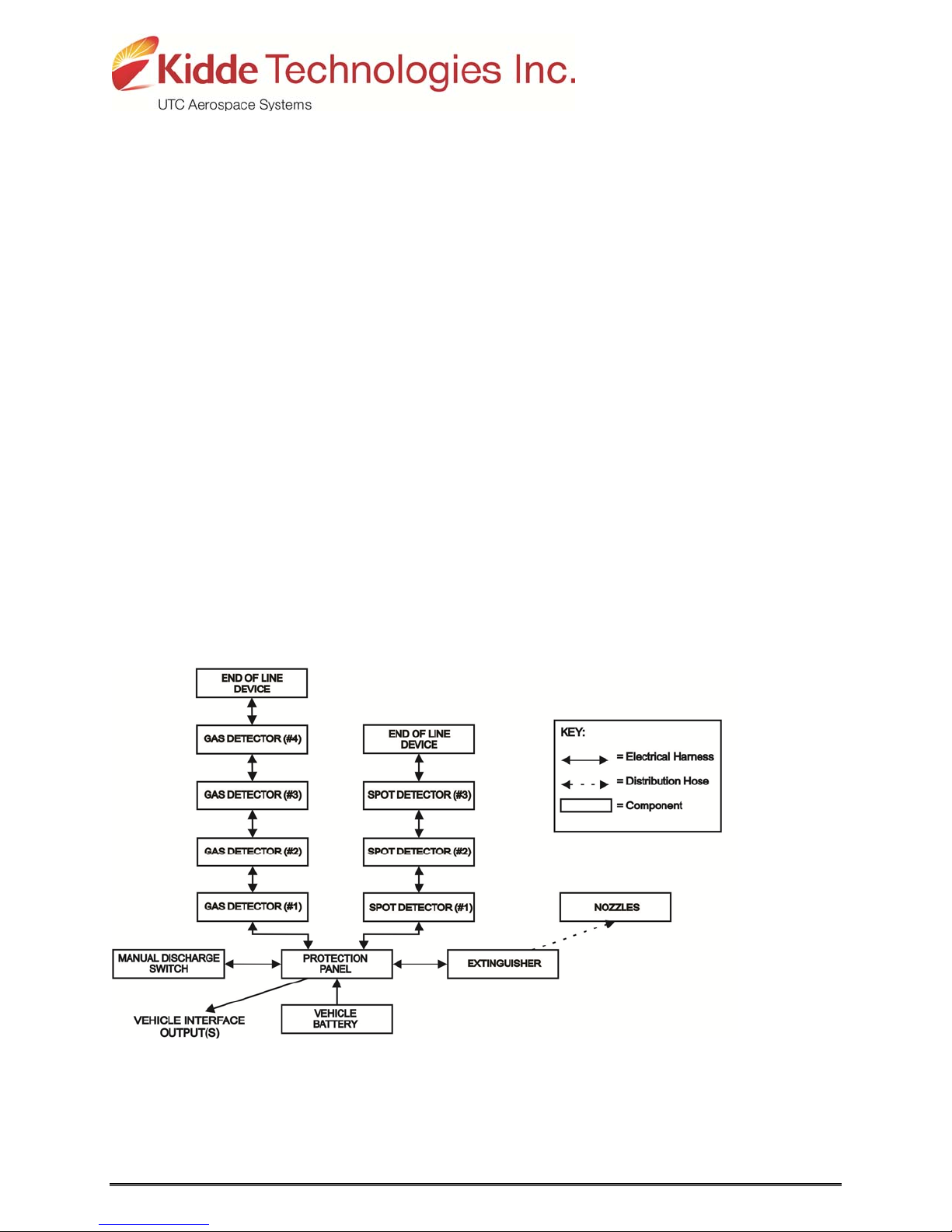
BLOCK DIAGRAM
A system block diagram is shown in Figure 1.
FIGURE 1 – SYSTEM BLOCK DIAGRAM
PROPRIETARY INFORMATION – Refer to the restrictions provided on the Title Page of this document.
EAR DATA - Subject to the export control restrictions on the Title Page of this document or file
3
Controlled by ECCN:EAR99

181922 Rev B
SYSTEM OPERATION
The state of the system is constantly monitored and is displayed to the driver via the protection
panel. The system provides visual and audial indicators to the driver when the state of the
system changes.
NORMAL CONDITION
During normal operating conditions (appropriate system power applied and no fault conditions
present), the protection panel’s system “OK” indicator is illuminated solid green.
FIRE SCENARIO
When a fire sensor detects a fire in the engine compartment, the Protection Panel’s FIRE
ALARM and the DELAY ENGINE STOP indicators illuminate, an audio alarm sounds, and the
HVAC shuts down immediately. Fifteen (15) seconds later the engine automatically shuts down
and the fire extinguisher automatically discharges.
Engine shutdown and extinguisher discharge may be delayed an additional fifteen (15) seconds
by depressing the Protection Panel’s DELAY ENGINE STOP indicator/switch.
The Manual Activation Switch may be activated to immediately discharge the Fire Extinguisher
and shutdown the engine and HVAC.
The system must be reset and the extinguisher removed and replaced in accordance with the
System Reset portion of this manual.
WARNING! THE ENGINE WILL STOP 15 SECONDS AFTER THE FIRE ALARM STARTS.
THE OPERATOR MUST BE PREPARED TO BRING THE VEHICLE TO A SAFE
STOP AS SOON AS THE ALARM SOUNDS. STEERING MAY BECOME
DIFFICULT AFTER ENGINE SHUTDOWN. IF MORE TIME IS REQUIRED, THE
“DELAY ENGINE STOP” SWITCH MAY BE PRESSED AND RELEASED FOR
AN ADDITIONAL 15 SECOND DELAY.
WARNING! THE EXTINGUISHER DISCHARGE MAY CAUSE AN OBSCURING CLOUD
BEHIND AND NEAR THE VEHICLE.
GAS TRACE LEAK (20% LEL) SCENARIO
When a gas sensor detects a trace leak, the Protection Panel’s GAS LEAK indicator illuminates
(blinking).
The system will reset itself and indications will clear when the gas dissipates below the trace
leak threshold.
PROPRIETARY INFORMATION – Refer to the restrictions provided on the Title Page of this document.
EAR DATA - Subject to the export control restrictions on the Title Page of this document or file
4
Controlled by ECCN:EAR99

181922 Rev B
GAS SIGNIFICANT LEAK (50% LEL) SCENARIO
When a gas sensor detects a significant leak, the Protection Panel’s GAS LEAK indicator
illuminates (steady-on) and an audio alarm sounds. The gas LEAK indicator and the audible
alarm warnings will stay on until the TEST/RESET button on the Protection Panel is pressed.
The status indicator on the individual Gas Leak Detector that detected the significant gas leak
will remain illuminated solid red until the system is reset in accordance with system reset portion
of this manual.
SYSTEM FAULT SCENARIO
The Protection Panel continuously monitors system integrity and displays the status via the
SYSTEM OK, FIRE TROUBLE, and GAS TROUBLE indicators. Refer to the Component
Description, Protection Panel portion of this manual for the operational description of the
indicators.
COMPONENT DESCRIPTION
PROTECTION PANEL (413484-1345)
The protection panel is located in the driver’s area and displays the current system status. The
Protection panel comprises the following:
SYSTEM OK indicator
o Illuminates solid green when appropriate power is applied to the system and no
trouble conditions exists
o Illuminates blinking green when power is low (under 22VDC)
o Off when power is insufficient
o Off when TROUBLE indicator is illuminated
FIRE TROUBLE indicator
Illuminates blinking yellow when a fault exists in the fire detection and suppression
circuits
Fire ALARM indicator
o Illuminates solid red when a fire is detected
o Illuminates blinking red when the MANUAL DISCHARGE switch is activated
Gas TROUBLE indicator
Illuminates solid yellow when a fault exists in the gas detection circuit
Gas ALARM indicator
o Illuminates blinking red when trace gas is detected (greater than 20%, but less than
50%)
o Illuminates solid red when significant gas is detected (greater than 50%)
Audible alarm
o Intermittent sound indicates fault condition when SYSTEM OK indicator is
extinguished
o Intermittent sound indicates low power condition when SYSTEM OK indicator is
blinking
o Continuous sound indicates fire alarm, manual discharge, or significant gas alarm
PROPRIETARY INFORMATION – Refer to the restrictions provided on the Title Page of this document.
EAR DATA - Subject to the export control restrictions on the Title Page of this document or file
5
Controlled by ECCN:EAR99

181922 Rev B
ALARM SILENCE switch
o Use to silence the audible alarm
TEST/RESET switch with DELAY ENGINE STOP indicator
During normal “System OK” state:
o Allows testing of indicators and audible alarm during standby operation
During Fire Event:
o Illuminates solid red when fire event is detected
o Illuminates blinking red when pressed and released for a 15 second additional delay.
o Returns to solid red illumination after additional time delay had elapsed
o Turns off when the shutdown signal has been activated
o Resets protection panel when pressed and released after a fire event or significant
gas leak
Early warning signal output
Engine shutdown signal output
Manual activation switch signal input
Operating Temperature Range
Quiescent Current
Operating Voltage
-40⁰F to 158⁰F (-40⁰C to 70⁰C)
50mA (Nominal) @ 24V
9 to 32Vdc
PROPRIETARY INFORMATION – Refer to the restrictions provided on the Title Page of this document.
EAR DATA - Subject to the export control restrictions on the Title Page of this document or file
FIGURE 2 - PROTECTION PANEL
6
Controlled by ECCN:EAR99
181922 Rev B
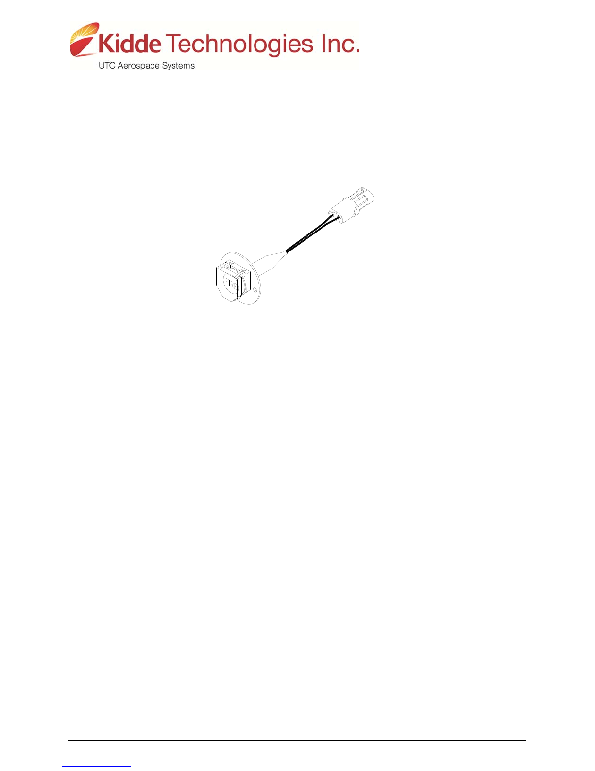
MANUAL ACTIVATION SWITCH (421317)
The Manual Activation Switch allows immediate system activation (extinguisher discharge and
engine shutdown) by the vehicle operator at any time. Activation of the switch is accomplished
by twisting and pulling the tamper seal (not shown) to remove, lifting the cover and pressing the
red “FIRE” button for more than half a second. After the Manual Activation Switch has been
activated, the Protection Panel’s FIRE ALARM indicator will blink until power has been cycled to
the system.
FIGURE 3 – MANUAL ACTIVATION SWITCH
(Depicted without Tamper Seal)
PROPRIETARY INFORMATION – Refer to the restrictions provided on the Title Page of this document.
EAR DATA - Subject to the export control restrictions on the Title Page of this document or file
7
Controlled by ECCN:EAR99
 Loading...