

Page 1

P/N 76-100016-001
®
PEGAsys
Intelligent Suppression-Control
and Fire-Alarm System
August 1999
Installation, Operation,
and Maintenance Manual
UL Listing File No. S2422
Factory Mutual Approval J.I. No. OB2A6.AY
R
LISTED
Fire Systems
Page 2

Page 3

PEGAsys
Intelligent Suppression-Control
and Fire-Alarm System
Installation, Operation,
And Maintenance Manual
Document No. PEGAsys
August 1999
Page 4

Page 5

This Manual Is To Be Used By Trained Distributors Only
FOREWORD
This manual is intended to clearly and accurately reflect the PEGAsys Fire Alarm/Suppression Control System. This publication describes the operation, installation and maintenance of the PEGAsys Fire Alarm/Suppression Control System, P/Ns 76-100000-501 for
Single-Loop System and 76-100000-600 for Multi-Loop System.
TERMS AND ABBREVIATIONS
ADA Americans with Disabilities Act
AI Addressable Contact Input Device
AO Addressable Relay Output Device
BPM Beats Per Minute
CCM Central Control Module
CCP Central Control Panel
EDP Electronic Data Processing
EOC Event Output Control
FCP Fire Control Panel
GUI Graphical User Interface
I/O Input/Output
ID Identification
IRI Industrial Risk Insurers
NC Normally Closed
ACCEPTANCES, APPROVALS, AND CERTIFICATIONS
NO Normally Open
NR Not Registered
NYC New York City
P/N Part Number
PAS Positive Alarm Sequence
PC Personnel Computer
PCS PEGAsys Configuration Software
PC Line Power/Communication Line (RX/TX Loop)
PS Power Supply
RCU Remote Control Unit
RTC Real Time Clock
RX/TX Receive Transmit
UL Underwriter Laboratories
VDC Voltage Direct Current
PEGAsys Single-Loop System (P/N 76-100000-501)
• UL: Underwriter’s Laboratories Listing File Number S2422.
• FM: Factory Mutual Engineering Corp. (Factory Mutual System) Approval J.I. Number 3005511
• CSFM: Pending.
• NYC: Pending.
PEGAsys Multi-Loop System (P/N 76-100000-600)
• UL: Underwriter’s Laboratories Listing File Number S2422.
• FM: Factory Mutual Engineering Corp. (Factory Mutual System) Approval J.I. Number 3005511
• CSFM: Pending.
• NYC: Pending.
i
Page 6

(THIS PAGE IS INTENTIONALLY LEFT BLANK)
ii
Page 7

TABLE OF CONTENTS
Forward .........................................................................................................................................................i
Terms and Abbreviations ................................................................................................................................i
Appendices ...................................................................................................................................................vi
List of Illustrations .......................................................................................................................................... vii
List of Tables ................................................................................................................................................. ix
Safety Summary ............................................................................................................................................x
PARAGRAPH TITLE PAGE
1 GENERAL INFORMATION ................................................................................................................................................1-1
1-1 Introduction ..................................................................................................................................................................... 1-1
1-1.1 System Description ........................................................................................................................................................ 1-1
1-1.2 System Components ..................................................................................................................................................... 1-1
1-2 Component Description .................................................................................................................................................1-1
1-2.1 Central Control Module (CCM) ....................................................................................................................................... 1-1
1-2.2 Display Module ............................................................................................................................................................... 1-1
1-2.3 Receiver/Transmitter Module (RX/TX) ............................................................................................................................ 1-2
1-2.4 Power Supply/Charger Assembly ..................................................................................................................................1-2
1-2.5 Basic Motherboard ......................................................................................................................................................... 1-2
1-2.6 Multi-Loop Motherboard .................................................................................................................................................1-3
1-2.7 Input/Output Modules .....................................................................................................................................................1-3
1-2.7.1 Signal Output Module ..................................................................................................................................................... 1-3
1-2.7.2 Relay Output Module ......................................................................................................................................................1-3
1-2.7.3 Agent Release Output Module .......................................................................................................................................1-4
1-2.7.4 City Tie Module ............................................................................................................................................................... 1-4
1-2.8 Standby Batteries............................................................................................................................................................1-4
1-2.9 Intelligent Loop Devices .................................................................................................................................................1-4
1-2.9.1 SmartOneTM Ionization Detectors ...................................................................................................................................1-4
1-2.9.2 SmartOne Photoelectric Detectors ................................................................................................................................1-5
1-2.9.3 SmartOne Heat Detectors ............................................................................................................................................. 1-5
1-2.10 SmartOne Detector Bases ............................................................................................................................................ 1-5
1-2.11 Addressable Contact Input Devices ..............................................................................................................................1-5
1-2.12 Addressable Relay Output Devices ...............................................................................................................................1-5
1-2.13 Model DH-2000 Air Duct Housing .................................................................................................................................. 1-5
1-2.14 Loop Isolator Devices .................................................................................................................................................... 1-6
1-3 System Specification ......................................................................................................................................................1-6
2 OPERATION ....................................................................................................................................................................2-1
2-1 Introduction ..................................................................................................................................................................... 2-1
2-1.1 Mode of Operation ..........................................................................................................................................................2-1
2-2 Control and Indicators ....................................................................................................................................................2-1
2-2.1 LCD Display ...................................................................................................................................................................2-1
2-2.2 Audible Device ................................................................................................................................................................ 2-2
2-2.3 Control and Indicator Description .................................................................................................................................. 2-2
2-3 System Security .............................................................................................................................................................. 2-2
2-3.1 Levels of Security............................................................................................................................................................ 2-2
2-3.2 Default Passwords......................................................................................................................................................... 2-2
2-3.3 Entering Passwords ......................................................................................................................................................2-2
2-4 System Power-Up .......................................................................................................................................................... 2-2
2-5 System Menus ................................................................................................................................................................2-4
2-5.1 Menu Structure ................................................................................................................................................................2-4
2-5.2 Accessing the System Menus ........................................................................................................................................ 2-4
2-5.3 Exiting the System Menus .............................................................................................................................................. 2-4
2-5.4 Menu Functions .............................................................................................................................................................. 2-4
2-5.4.1 Isolate Menu Function ....................................................................................................................................................2-4
2-5.4.2 List Menu Function .........................................................................................................................................................2-4
2-5.4.3 Set Menu Function ..........................................................................................................................................................2-4
2-5.4.4 Test Menu Function ........................................................................................................................................................2-4
2-6 Modes of Operation ........................................................................................................................................................ 2-5
2-6.1 Normal Standby Mode ....................................................................................................................................................2-5
2-6.2 Active Alarm Mode ........................................................................................................................................................... 2-5
2-6.2.1 Alarm Mode Indications .................................................................................................................................................. 2-5
2-6.2.2 Alarm Mode User Action ................................................................................................................................................. 2-5
iii
Page 8

TABLE OF CONTENTS (CONT.)
PARAGRAPH TITLE PAGE
2-6.3 Active Supervisory Trouble Mode ................................................................................................................................. 2-10
2-6.3.1 Supervisory Trouble Mode Indication ........................................................................................................................... 2-10
2-6.3.2 Supervisory Trouble Mode User Action ........................................................................................................................ 2-10
2-6.4 Active Trouble Mode ...................................................................................................................................................... 2-11
2-6.4.1 Trouble Mode Indications .............................................................................................................................................. 2-11
2-6.4.2 Trouble Mode User Action ............................................................................................................................................. 2-11
2-7 Printing Operation ......................................................................................................................................................... 2-11
2-8 System Programming ................................................................................................................................................... 2-11
2-8.1 EOC Programming........................................................................................................................................................2-11
2-8.1.1 Listing EOC Programming ........................................................................................................................................... 2-12
2-8.2 RTC Programming ....................................................................................................................................................... 2-12
2-8.2.1 Listing RTC Programming ........................................................................................................................................... 2-12
2-8.2.2 Enable/Disable RTC Program Line Numbers ............................................................................................................ 2-12
2-8.3 Types of Inputs and Outputs ........................................................................................................................................ 2-12
2-8.3.1 System Inputs ............................................................................................................................................................... 2-12
2-8.3.2 Remote Control Unit (RCU) ......................................................................................................................................... 2-12
2-8.3.3 RX/TX Loops ................................................................................................................................................................. 2-12
2-8.3.4 System Outputs ............................................................................................................................................................ 2-13
2-8.3.5 System I/O Modules ..................................................................................................................................................... 2-13
2-8.4 Addressing I/O Modules ............................................................................................................................................... 2-13
2-8.5 Registering I/O Module Assignments .......................................................................................................................... 2-13
2-8.5.1 Listing I/O Module Assignment .................................................................................................................................... 2-13
2-8.6 Addressing RCU’s ....................................................................................................................................................... 2-13
2-8.7 Registering RCU’s ....................................................................................................................................................... 2-14
2-8.7.1 Detector Registration ................................................................................................................................................... 2-14
2-8.7.2 Addressable Contact Monitor Registration .................................................................................................................. 2-14
2-8.7.3 Remote Relay Registration .......................................................................................................................................... 2-15
2-8.7.4 Listing all Registered RCU’s ....................................................................................................................................... 2-15
2-8.7.5 Un-registering RCU’s .................................................................................................................................................. 2-15
3 FUNCTIONAL DESCRIPTION .......................................................................................................................................... 3-1
3-1 Introduction ..................................................................................................................................................................... 3-1
3-2 Overall Block Diagram Description ................................................................................................................................ 3-1
3-3 Functional Descriptions ................................................................................................................................................. 3-2
3-3.1 Central Control Module ..................................................................................................................................................3-2
3-3.2 Receiver/Transmitter (RX/TX) Module ............................................................................................................................ 3-3
3-3.3 Power Supply/Charger Assembly, Revision A ................................................................................................................3-4
3-3.4 Power Supply/Charger Assembly, Revision C ............................................................................................................... 3-5
3-3.5 Multi-Loop I/O Motherboard ............................................................................................................................................3-6
3-3.6 Signal Output Module .....................................................................................................................................................3-7
3-3.7 Relay Output Module ......................................................................................................................................................3-8
3-3.8 Agent Release Module ................................................................................................................................................... 3-9
3-3.9 City Tie Module ............................................................................................................................................................. 3-10
3-3.10 Field Devices ................................................................................................................................................................. 3-11
3-3.11 SmartOne Ionization Detectors .................................................................................................................................... 3-11
3-3.12 SmartOne Photoelectric Detectors ............................................................................................................................... 3-11
3-3.13 SmartOne Heat Detectors ............................................................................................................................................3-11
3-3.14 Addressable Contact Input Devices .............................................................................................................................3-11
3-3.15 Addressable Relay Output Devices ............................................................................................................................. 3-12
3-3.16 Model DH-2000 Air Duct Housing ................................................................................................................................ 3-12
3-3.17 Loop Isolator Devices .................................................................................................................................................. 3-12
4 MAINTENANCE PROCEDURE .........................................................................................................................................4-1
4-1 Introduction ..................................................................................................................................................................... 4-1
4-2 Scheduled Maintenance ................................................................................................................................................4-1
4-3 Maintenance Procedures ............................................................................................................................................... 4-1
4-3.1 Lamp Test .......................................................................................................................................................................4-1
4-3.2 Loop Device Test ............................................................................................................................................................ 4-1
4-3.3 Battery Test ..................................................................................................................................................................... 4-1
4-3.4 Walk Test ........................................................................................................................................................................ 4-2
iv
Page 9

TABLE OF CONTENTS (CONT.)
PARAGRAPH TITLE PAGE
4-3.4.1 Walk Testing Detectors ..................................................................................................................................................4-2
4-3.4.2 Walk Test Procedure ......................................................................................................................................................4-2
4-3.5 Alarm Simulation Test (AST) .......................................................................................................................................... 4-2
4-3.5.1 AST Procedure ...............................................................................................................................................................4-3
4-4 Disarming and Rearming Release Circuits..................................................................................................................4-3
4-4.1 Disarming Release Circuits .......................................................................................................................................... 4-3
4-4.2 Arming Release Circuits ................................................................................................................................................ 4-3
4-5 Power-Down System ......................................................................................................................................................4-3
4-5.1 Power-Down Procedure .................................................................................................................................................4-3
4-6 Power-Up System .......................................................................................................................................................... 4-4
4-6.1 Power-Up Procedure...................................................................................................................................................... 4-4
5 TROUBLESHOOTING AND CORRECTIVE MAINTENANCE ............................................................................................. 5-1
5-1 Introduction ..................................................................................................................................................................... 5-1
5-2 Standard Fault Isolation Techniques ............................................................................................................................. 5-1
5-2.1 Visual Inspection ............................................................................................................................................................ 5-1
5-2.2 Power Checks ................................................................................................................................................................5-1
5-3 Troubleshooting .............................................................................................................................................................5-1
5-4 Removal and Replacement ...........................................................................................................................................5-2
5-4.1 Required Tools ............................................................................................................................................................... 5-2
5-4.2 Central Control Module ..................................................................................................................................................5-2
5-4.3 RX/TX Module .................................................................................................................................................................5-2
5-4.4 Field Devices .................................................................................................................................................................. 5-3
6 PARTS LIST .................................................................................................................................................................... 6-1
6-1 Introduction ..................................................................................................................................................................... 6-1
7 INSTALLATION ................................................................................................................................................................7-1
7-1 Introduction ..................................................................................................................................................................... 7-1
7-2 Materials Required For Installation ................................................................................................................................ 7-1
7-3 Installation Procedure For Central Control Panel .........................................................................................................7-1
7-4 Installation Procedure For Expansion Enclosures ........................................................................................................ 7-1
7-5 Installation Procedure For I/O Motherboard ...................................................................................................................7-2
7-6 Installation Procedure For Rx/Tx Module (Multi-Loop Only) ...........................................................................................7-2
7-7 Installation of I/O Modules ..............................................................................................................................................7-3
7-7.1 Signal Audible Output Module ........................................................................................................................................7-3
7-7.2 Relay Output Module ......................................................................................................................................................7-4
7-7.3 Agent Release Module ................................................................................................................................................... 7-4
7-7.4 City-Tie Output Module ...................................................................................................................................................7-4
7-7.6 Power Supply/Charger Assembly ..................................................................................................................................7-4
7-7.7 Power Supply/Charger Assembly, Expansion Enclosure ..............................................................................................7-4
7-7.8. Power Supply Communication Connections ................................................................................................................7-6
7-8 Connecting AC Power ....................................................................................................................................................7-6
7-9 Install And Connect DC Power ....................................................................................................................................... 7-6
7-9.1 Battery Enclosure ...........................................................................................................................................................7-6
7-9.2 Batteries .........................................................................................................................................................................7-6
7-10 Field Device Connection To RX/TX Module ....................................................................................................................7-7
7-10.1 Wiring the RX/TX PC Line ............................................................................................................................................... 7-7
7-11 Output Signal Connection .............................................................................................................................................. 7-9
7-12 External Power Failure Indicator Connection .............................................................................................................. 7-10
7-13 Detector Installation ..................................................................................................................................................... 7-10
7-14 Setting and Adjusting Smoke & Heat Detector Sensitivities ........................................................................................ 7-10
7-14.1 Setting and Adjusting Smoke and Heat Detector Sensitivity Procedure ..................................................................... 7-10
7-15 Addressable Contact Input Device Installation ............................................................................................................. 7-11
7-16 Addressable Relay Output Device Installation ............................................................................................................. 7-11
7-17 Installation Checkout ..................................................................................................................................................... 7-11
7-18 Connection of Peripherals ............................................................................................................................................ 7-11
7-18.1 Connecting a Terminal or Personal Computer ............................................................................................................7-11
7-18.2 Connecting a Printer ..................................................................................................................................................... 7-11
v
Page 10

APPENDICES
APPENDIX TITLE PAGE
A POWER SUPPLY REQUIREMENTS .............................................................................................................................. A-1
B SYSTEM EXPANSION .................................................................................................................................................... B-1
C RELEASING APPLICATIONS ......................................................................................................................................... C-1
D NOT USED .................................................................................................................................................................... D-1
E FACTORY MUTUAL SPRINKLER REQUIREMENTS .................................................................................................... E-1
F GLOSSARY .....................................................................................................................................................................F-1
G DISPLAY ABBREVIATIONS ............................................................................................................................................ G-1
H INDEX ............................................................................................................................................................................ H-1
I SYSTEM DRAWINGS ...................................................................................................................................................... I-1
J PEGAsys NETWORK INTERFACE CARD ...................................................................................................................... J-1
K ADDRESSABLE SIGNAL/SOUNDER ............................................................................................................................ K-1
L REMOTE DISPLAY CONTROL MODULE AND REMOTE DISPLAY MODULE ............................................................... L-1
M ADDRESSABLE ALARMLINE MODULE ........................................................................................................................ M-1
N NETWORKABLE CENTRAL CONTROL MODULE (NCCM) ......................................................................................... N-1
O CENTRAL STATION OPERATION .................................................................................................................................. O-1
vi
Page 11

LIST OF ILLUSTRATIONS
FIGURE TITLE PAGE
1-1 PEGAsys System Overall Diagram ................................................................................................................................ 1-0
1-2 Central Control Module (CCM) ....................................................................................................................................... 1-2
1-3 Display Module Assembly .............................................................................................................................................. 1-2
1-4 Receiver/Transmitter Module (RX/TX) ............................................................................................................................1-2
1-5 Power Supply/Charger Assembly ..................................................................................................................................1-2
1-6 Basic I/O Motherboard ....................................................................................................................................................1-3
1-7 Multi-Loop I/O Motherboard ............................................................................................................................................1-3
1-8 Signal Output Module ..................................................................................................................................................... 1-3
1-9 Relay Output Module ...................................................................................................................................................... 1-4
1-10 Agent Release Output Module .......................................................................................................................................1-4
1-11 City-Tie Module ...............................................................................................................................................................1-4
1-12 Battery Enclosure ...........................................................................................................................................................1-4
1-13 SmartOneTM Detection Device .......................................................................................................................................1-4
1-14 4-inch Detector Base ...................................................................................................................................................... 1-5
1-15 6-inch Detector Base ...................................................................................................................................................... 1-5
1-16 Addressable Contact Input Device .................................................................................................................................1-5
1-17 Addressable Relay Output Device .................................................................................................................................1-5
1-18 Air Duct Housing ............................................................................................................................................................ 1-5
1-19 Loop Isolator, Stand-Alone .............................................................................................................................................1-6
1-20 Loop Isolator, RX/TX Mount ............................................................................................................................................ 1-6
1-21 Loop Isolator, 6” Detector Base Mount ........................................................................................................................... 1-6
2-1 System Front Panel ........................................................................................................................................................ 2-1
2-2 Level One Menu Structure .............................................................................................................................................. 2-6
2-3 Level Two Menu Structure ............................................................................................................................................... 2-7
3-1 Overall Block Diagram, Single-Loop System ................................................................................................................3-1
3-2 Overall Block Diagram, Multi-Loop System ...................................................................................................................3-1
3-3 Central Control Module, Details .....................................................................................................................................3-2
3-4 Receiver/Transmitter Module, Details ...........................................................................................................................3-3
3-5 Obsolete Power Supply/Charger Assembly, Revision A, Details ..................................................................................3-4
3-6 Power Supply/Charger Assembly, Revision C, Details .................................................................................................3-5
3-7 Multi-Loop I/O Motherboard, Details .............................................................................................................................. 3-6
3-8 Signal Output Module, Details ....................................................................................................................................... 3-7
3-9 Relay Output Module, Details ......................................................................................................................................... 3-8
3-10 Agent Release Output Module, Details ..........................................................................................................................3-9
3-11 City Tie Module, Details ................................................................................................................................................ 3-10
3-12 Typical Detector ............................................................................................................................................................. 3-11
3-13 Addressable Contact Input Device ............................................................................................................................... 3-12
3-14 Addressable Relay Output Device ............................................................................................................................... 3-12
3-15 DH-2000 Air Duct Housing ........................................................................................................................................... 3-12
3-16 Loop Isolator, RX/TX Mount .......................................................................................................................................... 3-13
3-17 Loop Isolator, Stand-Alone ........................................................................................................................................... 3-13
3-18 Loop Isolator, 6” Detector Base Mount ......................................................................................................................... 3-13
5-1 Installation for Single Loop ............................................................................................................................................ 5-2
5-2 Installation for Multi-Loop ............................................................................................................................................... 5-2
7-1 CCP Installation Drawing ............................................................................................................................................... 7-1
7-2 Back Plate, I/O Motherboard & 4 P.S. ..............................................................................................................................7-2
7-3 Back Plate, 8 P.S. ............................................................................................................................................................7-2
7-4 Back Plate, 2 I/O Motherboard ........................................................................................................................................ 7-2
7-5 Installation for Multi-Loop ............................................................................................................................................... 7-3
7-6 Power Supply/Charger (Rev A), Wiring Diagram ...........................................................................................................7-4
7-7 Power Supply/Charger (Rev C), Wiring Diagram ..........................................................................................................7-5
7-8 Power Supply/Charger (Rev A), Wiring Diagram for Expansion Enclosure .................................................................. 7-5
7-9 Power Supply/Charger (Rev C), Wiring Diagram for Expansion Enclosure .................................................................7-5
7-10 Battery Enclosure ...........................................................................................................................................................7-7
7-11 Conduit to CCP ...............................................................................................................................................................7-7
7-12 Shielded Wire to CCP .................................................................................................................................................... 7-7
7-13 Style 4, RX/TX PC Line Connections ..............................................................................................................................7-8
vii
Page 12

LIST OF ILLUSTRATIONS (CONT.)
FIGURE TITLE PAGE
7-14 Style 6, RX/TX PC Line Connections ..............................................................................................................................7-8
7-15 Style 6, RX/TX PC Line Connections with Loop Isolators .............................................................................................. 7-9
7-16 Style 7, RX/TX PC Line Connection ................................................................................................................................7-9
7-17 CCM Printer Port ........................................................................................................................................................... 7-12
viii
Page 13

LIST OF TABLES
TABLES TITLE PAGE
1-1 System Specification ......................................................................................................................................................1-6
2-1 Controls and Indicators .................................................................................................................................................. 2-3
2-2 Isolate Menu Function ....................................................................................................................................................2-8
2-3 List Menu Function .........................................................................................................................................................2-8
2-4 Set Menu Function ..........................................................................................................................................................2-9
2-5 Test Menu Function ...................................................................................................................................................... 2-10
3-1 Multi-Loop I/O Motherboard Connectors ........................................................................................................................ 3-6
3-2 Approved Release Output Devices ................................................................................................................................ 3-9
5-1 Troubleshooting Index ...................................................................................................................................................5-1
5-2 RX/TX Configuration Selection ....................................................................................................................................... 5-3
6-1 PEGAsys System Parts List ........................................................................................................................................... 6-1
7-1 RX/TX Configuration Selection ....................................................................................................................................... 7-3
7-2 Aux. Power Supply Module Connections to Rev. A .........................................................................................................7-5
7-3 Aux. Power Supply Module Connections to Rev. C ........................................................................................................ 7-5
ix
Page 14

SAFETY SUMMARY
Installation Precautions Adherence to the following will aid in problem-free installation with long-term reliability:
Warning - Several different sources of power can be connected to this fire alarm control panel. Disconnect all sources of power
before servicing. Control unit and associated equipment may be damaged by removing and/or inserting cards, modules, or interconnecting cables while the unit is energized. Do not attempt to install, service, or operate this unit until this manual is read and understood.
CAUTION - System Reacceptance Test after Software Changes: To ensure proper system operation, this product must be tested in
accordance with NFPA - 1996 Chapter 7 after any programming operation or change in site-specific software. Reacceptance testing is
required after any change, addition or deletion of system components, or after any modification, repair or adjustment to system hardware
or wiring.
All components, circuits, system operations, or software functions known to be affected by a change must be 100% tested. In addition,
to ensure that other operations are not inadvertently affected, at least 10% of initiating devices that are not directly affected by the change,
up to a maximum of 50 devices, must also be tested and proper system operation verified.
This system meets NFPA requirements for operation at 0 to 49° C and at a relative humidity of 85% RH (non-condensing) @ 30°C.
However, the useful life of the system’s standby batteries and the electronic components may be adversely affected by extreme temperature ranges and humidity. Therefore, it is recommended that this system and its peripherals be installed in an environment with a nominal
room temperature of 60-80°F.
Like all solid state electronic devices, this system may operate erratically or can be damaged when subjected to lightning induced
transients. Although no system is completely immune from lightning transients and interference, proper grounding will reduce susceptibility. The use of overhead or outside aerial wiring is not recommended due to the increased susceptibility to nearby lightning
strikes. Consult with the Applications Engineering Department if any problems are anticipated or encountered.
Disconnect AC power and batteries prior to removing or inserting circuit boards. Failure to do so can damage circuits.
Remove all electronic assemblies prior to any drilling, filing, reaming, or punching of the enclosure. When possible, make all cable
entries from the sides. Before making modifications, verify that they will not interfere with battery and printed circuit board location.
Do not over tighten screw terminals, over tightening may damage threads, resulting in reduced terminal contact pressure and difficult
with screw terminal removal.
This system contains static-sensitive components. Always ground yourself with a proper wrist strap before handling any circuits so that
static charges are removed from the body. Use static suppressive packaging to protect electronic assemblies removed from the unit.
Follow the Instructions in the installation, operating, and programming manuals. These instructions must be followed to avoid damage to
the control panel and associated equipment. PEGAsys operation and reliability depend upon proper installation.
Fire Alarm System Limitations While installing a fire alarm system may make lower insurance
rates possible, it is not a substitute for fire insurance!
An automatic fire alarm system - typically made up of smoke detectors, heat detectors, manual pull stations, audible warning devices,
and a fire alarm control with remote notification-capability can provide early warning of a developing fire. Such a system, however, does
not assure protection against property damage or loss of life resulting from a fire.
Any fire alarm system may fail for a variety of reasons:
Smoke detectors may not sense fire where smoke cannot reach the detectors such as in chimneys, in walls, or roofs, or on the other side
of closed doors. Smoke detectors also may not sense a fire on another level or floor of a building. A second floor detector, for example,
may not sense a first floor or basement fire. Furthermore, all types of smoke detectors - both ionization and photoelectric types, have
sensing limitations. No type of smoke detector can sense every kind of fire caused by carelessness and safety hazards like smoking in
bed, violent explosions, escaping gas, improper storage of flammable materials, overloaded electrical circuits, children playing with
matches, or arson.
Audible warning devices such as bells may not alert people if these devices are located on the other side of closed or partly open doors
or are located on another floor of a building.
A fire alarm system will not operate without electrical power. If AC power fails, the system will operate from standby batteries only for a
specified time.
Rate-of-Rise heat detectors may be subject to reduced sensitivity over time. For this reason, the rate-of-rise feature of each detector
should be tested at least once per year by a qualified fire protection specialist.
x
Page 15

Auxiliary Equipment used in the system may not be technically compatible with the control panel. It is essential to use only equipment
listed for service with your control panel.
Telephone lines needed to transmit alarm signals from a premise to a central monitoring station may be out of service or temporarily
disabled.
The most common cause of fire alarm malfunctions, however, is inadequate maintenance. All devices and system wiring should be
tested and maintained by professional fire alarm installers following written procedures supplied with each device. System inspection
and testing should be scheduled monthly or as required by National and/or local fire codes. Adequate written records of all inspections
should be kept.
GENERAL SAFETY NOTICES The following must be observed to maintain personnel safety.
The following general safety notices supplement specific warnings and cautions appearing in the manual. The safety precautions in this
section must be understood and applied during operation and maintenance. This manual is to be used by trained distributors/technicians.
The entire manual should be read and fully understood prior to installation.
TEST EQUIPMENT
Make certain test equipment is in good operating condition. Do not touch live equipment or personnel working on live equipment while
holding a test meter. Some types of measuring devices should not be grounded; these devices should not be held when taking measurements.
FIRST AID
Any injury, no matter how slight, should never go unattended. Always obtain first aid or medical attention immediately.
GENERAL PRECAUTIONS
The following general safety precautions are to be observed at all times:
1. All electrical components associated with equipment shall be installed and grounded in accordance with NEC, NFPA and local
regulation requirements.
2. Special precautionary measures are essential to prevent applying power to equipment at any time maintenance work is in progress.
3. Before working on electrical equipment, use a voltmeter to ensure that system is not energized.
4. When working near electricity, do not use metal rules, flashlights, metallic pencils, or any other objects having exposed conductive
material.
5. When connecting a meter to terminals for measurement, use range higher than expected voltage.
xi
Page 16

Page 17

Intelligent Suppression Control/Fire Alarm System
CHAPTER 1
GENERAL INFORMATION
1-1 INTRODUCTION
This manual contains the operation, maintenance, troubleshooting, parts listing, and installation information necessary to support the PEGAsys Intelligent Suppression Control and Fire Alarm
System.
NOTE: This manual is to be used by trained distributors only.
The entire manual should be read and fully understood
prior to installation.
1-1.1 System Description
PEGAsys is a fire alarm/suppression control system which can
be used for local, auxiliary, remote protective signaling and releasing device service. The system is a microprocessor based
design for use with intelligent detectors and loop devices.
The system utilizes distributed intelligent field devices. These
devices are typically smoke detectors, contact input devices
relay outputs and signal output modules which represent a single
fire alarm initiation/indicating zone. Each device contains its own
data transceiver, micro controller, 4k of memory and applicable
algorithms which allows each device to operate independent of
the control system. These unique devices have the ability to
analyze information, make decisions and store information within
themselves. They communicate with the PEGAsys system using the BIP protocol which utilizes a two-wire (Style 4), four wire
(Style 6) or isolated (Style 7) multiplex trunk. The PEGAsys can
support up to 255 device addresses per loop with a maximum
of 8 loops for a total of 2040 Intelligent device points per system.
The PEGAsys is capable of controlling a wide variety of auxiliary devices, such as relays, audible visual indicating signal
devices and agent/sprinkler release systems. The system also
supports the use of serial printers which provide hard copy of
system status information.
1-1.2 System Components
The system is comprised of three major components as shown
in Figure 1-1: the Central Control Panel (CCP) communicates
with the field devices and drives output devices such as alarm
signals that communicate with central stations and various types
of control equipment. A display panel located on the CCP provides system status LED’s, Control Switches and a 80-character LCD for alphanumeric display of system status information.
The single-loop PEGAsys Central Control Panel (P/N 76100000-501) consists of the Central Control Module (CCM) assembly, one receiver/transmitter (RX/TX) module and one power
supply assembly. Optionally the system can add a motherboard
assembly which allow the installation of optional output modules. An auxiliary power supply module can be added which
increases the base system power supply capacity to 8.0 amps
at 24 VDC.
PEGAsys
In multi-loop form the PEGAsys ML panel (P/N 76-100000-600)
consists of a CCM, one power-supply assembly, one RX/TX module and one multi-loop motherboard mounted in the enclosure.
The unique multi-loop motherboard provides the ability to connect
up to eight RX/TX modules to the system allowing a full 2040 addressable points to be connected to the PEGAsys ML system.
Auxiliary enclosures are available to allow the system to be expanded. The auxiliary enclosure has the same dimensions as that
of the main enclosure with the absence of the window in the door.
There are optional back planes which install in the expansion enclosure. This allows the number of I/O modules and system power
supplies to be expanded. To allow for maximum system flexibility
expansion enclosure(s) and backplane(s) can be added to the
system. Refer to Appendix B for further system expansion details.
1-2 COMPONENT DESCRIPTION
The following paragraphs give a brief description of each components used in the PEGAsys system. For functional descriptions of each component see Chapter 3 of this manual.
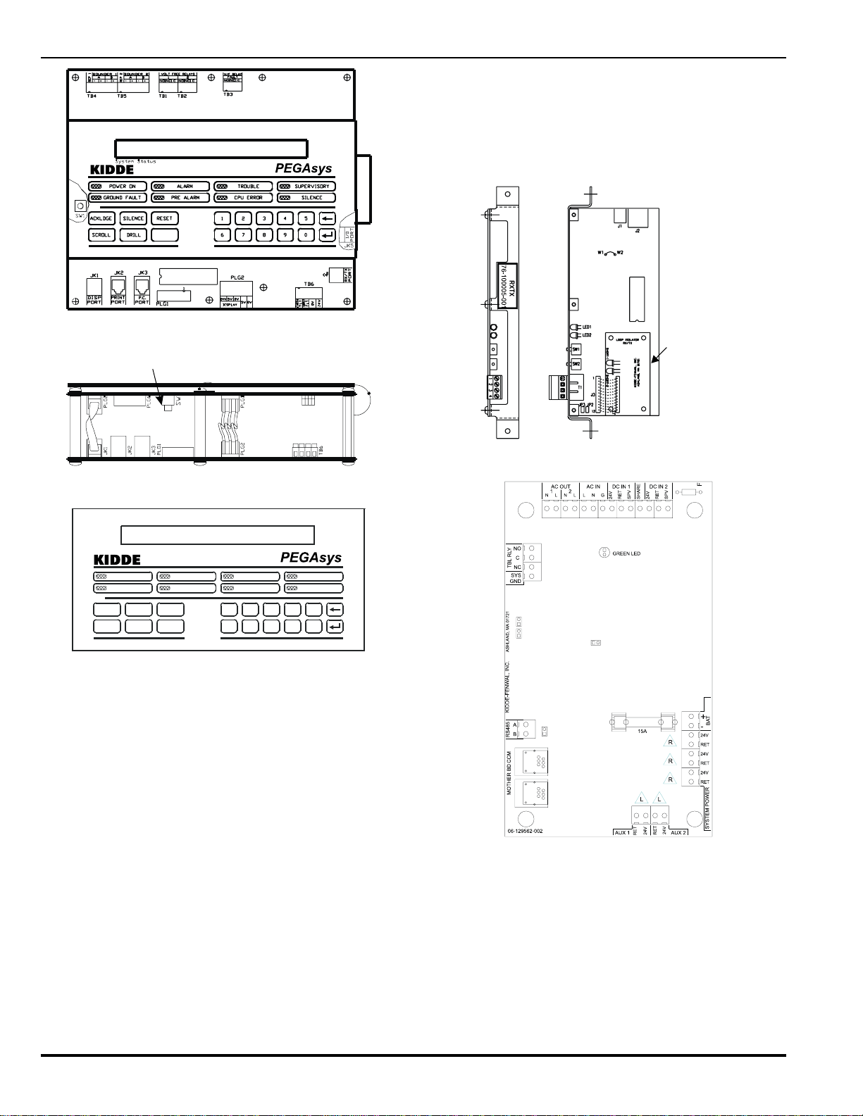
1-2.1 Central Control Module (CCM)
The CCM assembly is the heart of the system and is comprised
of two PCB assemblies, the display module and the main processor module. The CCM controls the operation and supervision of all the system modules and software within the PEGAsys
system. It receives loop device data from the RX/TX module,
processes the data based on pre-programmed instructions and
transmits output commands to the output modules, field devices,
and display module(s).
1-2.2 Display Module
The display module assembly, attached to the main processor
PCB, provides the system with the operator interface for control
switches, system status LED’s, system trouble/alarm buzzer, a
80-character (2 x 40) LCD display and an integral numeric keypad. The keypad is used for entering the security password and
navigating through the user menus. The system buzzer provides two distinctly different signaling patterns for audible warning of system alarms and troubles.
76-100016-001
1-1 August 1999
Page 18
PEGAsys
Display Reset Switch
Intelligent Suppression Control/Fire Alarm System
• Battery charging and supervision
• AC power supervision
• 24 VDC supervision
• Battery load test
• 24 VDC ground fault detection (+/-)
• Auxiliary 24 VDC outputs
Loop Isolator
for Style 7
Figure 1-2. Central Control Module (CCM)
System Status
POWER ON
GROUND FAULT
ACKLDGE RESET
SILENCE
SCROLL DRILL2DRILL
ALARM
PREALARM
TROUBLE
CPU ERROR
14
7890
6
SUPERVISORY
SILENCE
3
5
Figure 1-3. Display Module Assembly
1-2.3 Receiver/Transmitter Module (RX/TX)
The RX/TX functions as the hardware & software interface between the field devices and the CCM. The RX/TX receives control requests from the CCM and establishes communications
with the field devices. The RX/TX receives status changes from
the field devices and reports these changes to the CCM. The
RX/TX shown in Figure 1-4 is capable of communicating with
up to 255 intelligent devices and complies with the wiring requirements of NFPA Style 4, 6 & 7 (with the use of the loop
isolator device). Style 4 initiation circuit wiring will permit “T”
tapping, or branch circuitry.
Figure 1-4. Receiver/Transmitter Module (RX/TX)
Figure 1-5. Power Supply/Charger Assembly
1-2.4 Power Supply/Charger Assembly
The power supply/charger assembly (P/N 76-100009-010) is
comprised of a printed circuit board (PCB) assembly and a AC/
DC switching power supply unit. The switching power supply
unit provides 4 amps of 24 VDC from the 120/240 VAC input
power. The PCB assembly is a microprocessor based unit which
provides the system with:
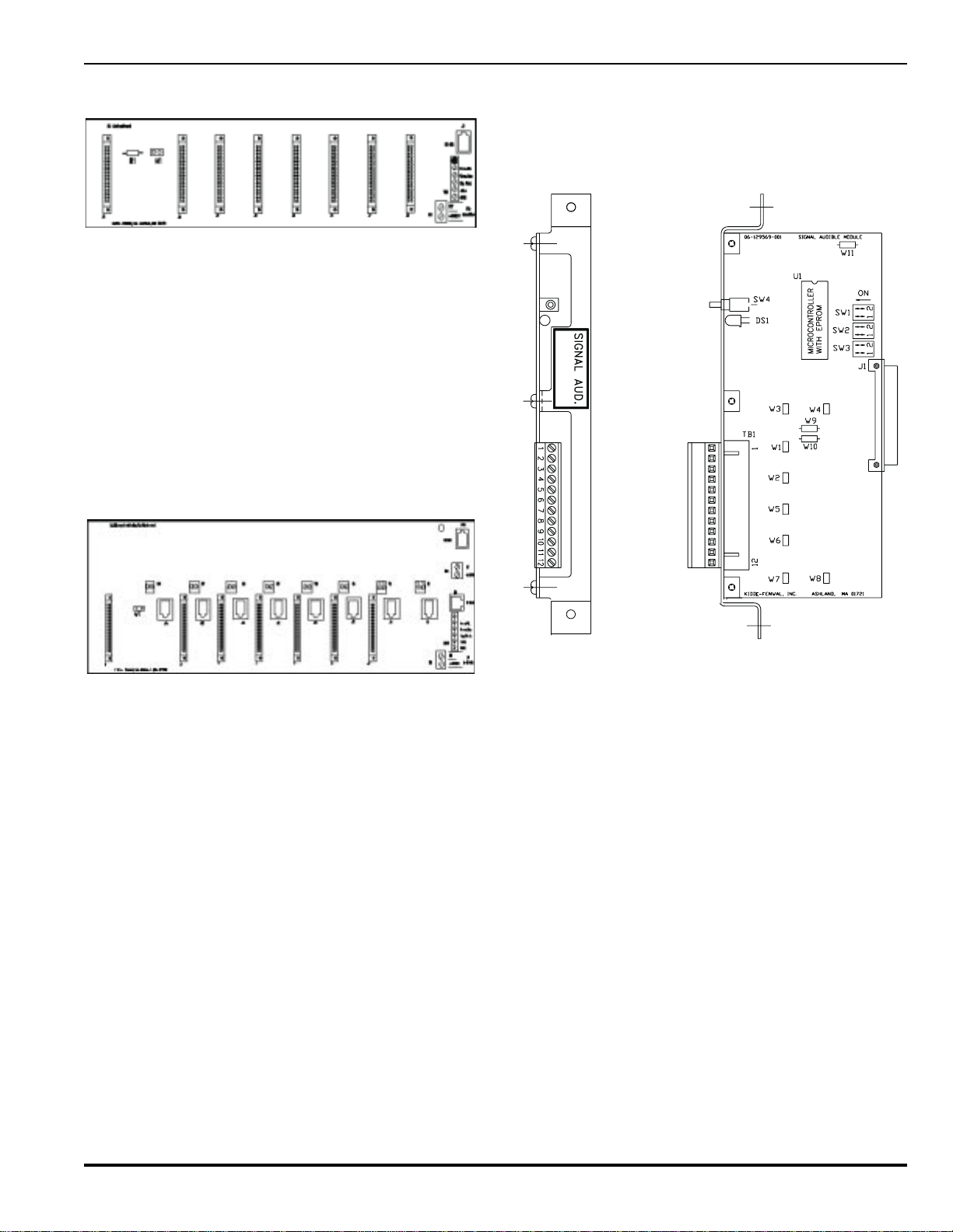
1-2.5 Basic Motherboard
The basic I/O motherboard assembly (P/N 76-100007-001) is
an assembly which can accept up to 8 I/O module circuit board
assemblies. The motherboard is mounted to the back of the
system enclosure and /or the auxiliary enclosures. It distributes
the system 24 VDC power and I/O bus communications to the I/
O modules. The I/O bus communications are provided by a RJ12 (flat phone cable) style connection. The 24 VDC is provided
by the system power supply via a 2-conductor wiring harness.
1-2August 1999 76-100016-001
Page 19
Intelligent Suppression Control/Fire Alarm System
PEGAsys
The I/O motherboard mounts to standoffs on the back of the main
and expansion enclosures with screws provided.
Figure 1-6. Basic I/O Motherboard
1-2.6 Multi-Loop Motherboard
The multi-loop I/O motherboard assembly (P/N 76-100017-001)
is an assembly which can accept up to 8 RX/TX modules and
provide connections for up to 7 I/O module circuit board assemblies. The ML motherboard is mounted to standoffs on the
back of the main system enclosure. It distributes system 24
VDC power, CCM-RX/TX communications for up to 8 RX/TX
modules and I/O bus communications to the I/O modules. The
I/O bus communications are provided by a RJ-12 (flat phone
cable) style connection. A single RJ-12 connection connects
the ML motherboard to the CCM for RX/TX communications.
The 24 VDC is provided by the system power supply via a 2conductor wiring harness.
1-2.7.1 SIGNAL OUTPUT MODULE
The PEGAsys panel has the capacity for a maximum of (8) Alarm
Sounder/Signal Output cards, thus providing 32 possible signal circuits. Each Alarm Sounder/Signal Output card, Figure 18, is equipped with supervised 24 VDC outputs which can
operate as Style “Y” or Style “Z” indicating circuits.
76-100003-001
Figure 1-7. Multi-Loop I/O Motherboard
1-2.7 Input/Output Modules
The optional input/output modules allow the PEGAsys system
to interface with external auxiliary devices. These auxiliary devices can be audible/visual signal devices, HVAC systems, elevator recall, power shut down, remote annunciators, agent/
sprinkler release system and any other control type input or
output which may need to be interfaced to the system.
The input and output modules plug into the motherboard assembly located on the back plate of the system enclosure. Each
I/O module occupies one slot in the motherboard assembly which
has 8 slots available. The I/O modules and the CCM communicate over the RS-485 based I/O bus, which uses a 6-conductor
phone type cable to connect the CCM to the motherboard.
The PEGAsys single-loop panel has the ability to support a
maximum of 16 I/O modules, in any combination. However, no
more than 8 of any one type of module can be used. If using a
City-Tie module, the limit is one per system.
The PEGAsys multi-Loop panel has the ability to support a maximum of 23 I/O modules, in any combination, on the system.
However, no more than 8 of any one type module can be used.
If using a City-Tie module, the limit is one per system.
The following paragraphs describe each available I/O module
in greater detail.
Figure 1-8. Signal Output Module
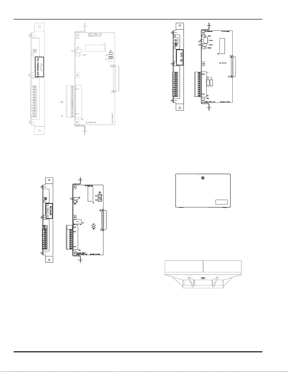
1-2.7.2 RELAY OUTPUT MODULE
The PEGAsys panel has the capacity for a maximum of 8 Auxiliary Relay Output cards, allowing up to 32 relays. Each Auxiliary Relay Output card is equipped with four (4), Form C,
dry-contact relay outputs. The ability to isolate an individual relay
output is provided through the system operator menu.
76-100016-001
1-3 August 1999
Page 20
PEGAsys
Figure 1-9. Relay Output Module
1-2.7.3 AGENT RELEASE OUTPUT MODULE
The PEGAsys panel has the capacity for a maximum of 8 agent
release output modules, providing up to 8 release circuits and
24 maximum signal outputs on those modules.
Intelligent Suppression Control/Fire Alarm System
76-100002-001
Figure 1-11. City Tie Module
1-2.8 Standby Batteries
Space is provided within the central control panel enclosure for
up to two (2) 12-V, 17 Amp Hour, sealed lead-acid batteries
used for 24, 60 or 90 hour standby operation. If additional batteries are required, an optional battery enclosure is available.
The enclosure (Figure 1-12) is a heavy duty steel cabinet which
can house up to two 40AH batteries. For installation information see Paragraph 7-9.1.
Figure 1-10. Agent Release Output Module
1-2.7.4 CITY-TIE MODULE
The City-Tie (Notification) Module will provide connection and
operation for local energy, shunt type master box and reverse
polarity styles of output.
FIREALARM SYSTEM
STANDBYBATTERIES
KIDDE
Figure 1-12. Battery Enclosure
1-2.9 Intelligent Loop Devices
The SmartOneTM Series of Intelligent Fire Alarm devices provide the PEGAsys control system with smoke and heat detection and necessary monitoring and control functions required
by today’s advanced fire alarm systems. The following paragraphs describe each available intelligent detection device.
Figure 1-13. SmartOne Detection Device
1-2.9.1 SmartOne IONIZATION DETECTORS
The SmartOne Ionization smoke detectors provide true distributed-intelligence, addressable microprocessor-based smoke
detection to the PEGAsys system.
1-4August 1999 76-100016-001
Page 21
Intelligent Suppression Control/Fire Alarm System
1-2.9.2 SmartOne PHOTOELECTRIC DETECTORS
The SmartOne Photoelectric smoke detectors provide true distributed-intelligence, addressable microprocessor-based smoke
detection to the PEGAsys system.
1-2.9.3 SmartOne HEAT DETECTORS
The SmartOne Thermistor heat detectors provide true distributed-intelligence, addressable, microprocessor-based heat detection to the PEGAsys system.
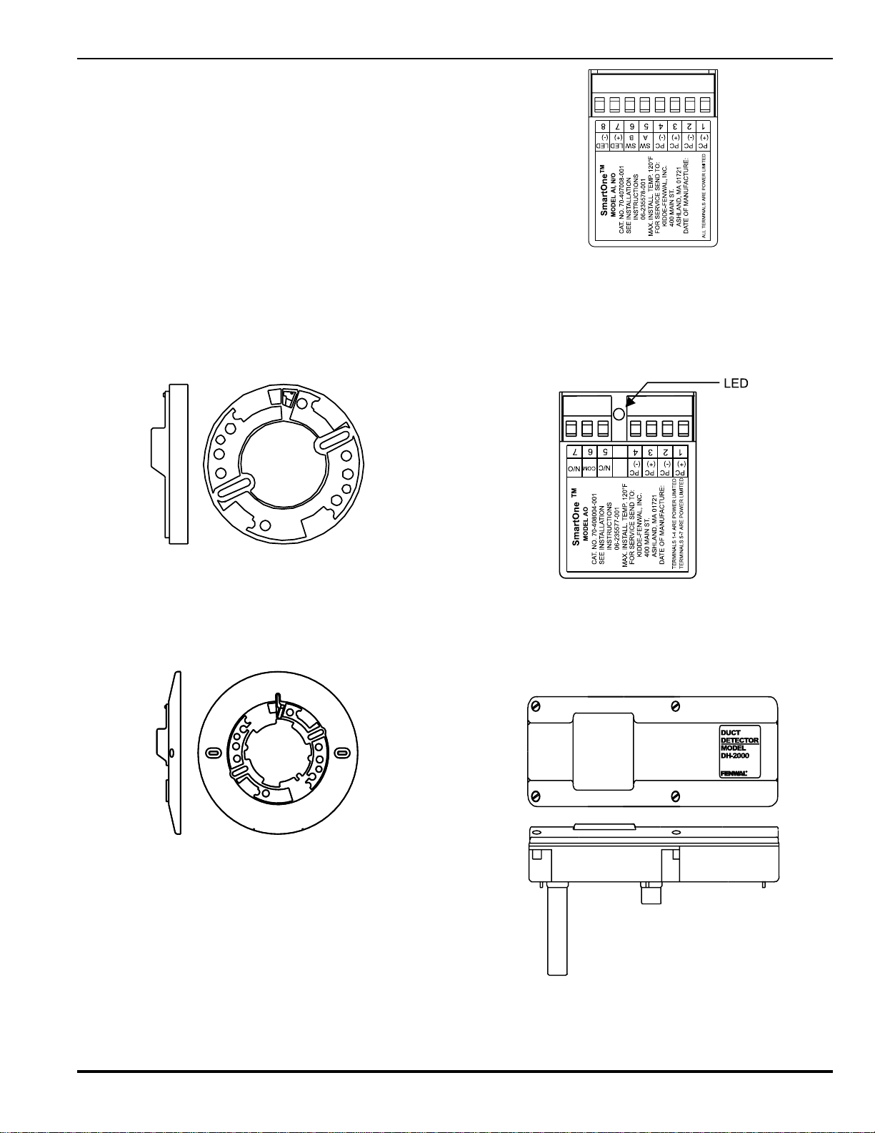
1-2.10 SmartOne Detector Bases
The SmartOne series of detection devices all use universal
mounting bases which are available in three styles. The 4SB is
a European-Style 4-inch base whose outside diameter matches
that of the low profile SmartOne detectors, which when combined, provides a very attractive unit. The 4SB, shown in Figure
1-14, mounts to standard 3, 3.5-inch, or 100-mm electrical boxes
with ease.
PEGAsys
Figure 1-16. Addressable Contact Input Device
1-2.12 Addressable Relay Output Devices
The addressable relay output device (P/N 70-408004-001) provides the PEGAsys system with a Form-C dry-contact interface
for remote control applications.
Figure 1-14. Four-inch Detector Base
The 6SB model, shown above, is a traditional style detector
base with an integral trim ring which provides coverage for any
inconsistencies between the electrical box and ceiling material.
The 6SB mounts to standard 3, 3.5 and 4 inch electrical boxes
with ease.
Figure 1-15. 6-inch Detector Base
1-2.11 Addressable Contact Input Devices
The SmartOne Contact Monitor (P/N 70-407008-00X) allows
an installer the ability to interface typical NO/NC fire alarm devices, such as water flow and tamper switches to the PEGAsys
system. The contact monitor is also used to interface to the
manual alarm, manual release and abort stations.
Figure 1-17. Addressable Relay Output Device
1-2.13 Model DH-2000 Air Duct Housing
The DH-2000 air duct housing is designed for detecting particles of combustion products in air-handling systems.
76-100016-001
Figure 1-18. Air Duct Housing
1-5 August 1999
Page 22

PEGAsys
Intelligent Suppression Control/Fire Alarm System
1-2.14 Loop Isolator Devices
The SmartOne series of loop devices, shown in Figures 1-19
through 1-21, offer optional loop isolation which protects the
loop from wire to wire short conditions (NFPA Style 7.0).
Figure 1-19. Loop Isolator, Stand-Alone
SHORT-1 SHORT-2
J1
Underwriters
Laboratories Inc.
R
REFER TO
INSTALLATION MANUAL
P/N 76-100016-001
FOR MODULE INSTALL.
PROCEDURES
LISTED
DS2 DS1
R
KIDDE-FENWAL, INC.
ASHLAND, MA 01721
LOOP ISOLATOR
RX/TX
Table 1-1. System Specifications
METISCITSIRETCARAHC
ylppuSrewoP
:tnemeriuqeRrewoP*zH06/05,V022/021
)eludoMreP(tupnI.S.P
spmA9.1,CAV021
spmA59.,CAV022
)eludoMreP(tuptuO.S.PspmA4,CDV42
:tuptuOregrahC.taBspmA3,CDV4.62
)2(:stuptuO.xuAhcaespmA5.1,CDV42
MCC
:tuptuOlangiSspmA2,CDV42
:tuptuOesaeleRspmA2,CDV42
:gnitaRtcatnoCyaleRCDV03@pmA1
:gnitaRyaleRelbuorTCDV03@pmA1
eludoMXTXR
:egatloV.xaMCDV4.62
:egatloV.niMCDV0.91
:ecnaticapaCeniL.xaMFu0.1
:ecnatsiseReniL.xaMsmhO62
elbasserddA.xaM
:seciveD
XTXRrep552
eludoMesaeleR
Figure 1-20. Loop Isolator, RX/TX Mount
Figure 1-21. Loop Isolator, 6" Detector Base Mount
1-3 SYSTEM SPECIFICATION
System power specifications are outlined in Table 1-1.
tuptuOesaeleRCDV42@spmA2
tuptuOlangiShcaeCDV42@spmA2
:epyTtuptuOesaeleR
eludoMelbiduAlangiS
:stuptuOlangiS
eludoMyaleR
:gnitaRtcatnoC
eludoMeiTytiC
:tcatnoCtnuhS
:tuptuOygrenElacoL
:yrosivrepuSygrenElacoLAm11
:daoLygrenElacoL
gnisaelerfoelbapaC
noisserppus(sdionelos
)relknirpsdna
elyts)2(ro"Y"elyts)4(
CDV42@spmA2"Z"
hcae
,stcatnoCCmroF)4(
roCDV03@spmA2
CAV021@pmA1
,CDV42@spmA5
evitsiseR
,CDV42@.xamAm005
.miLtnerruC
tnerruCpirTxoBretsaM
lacipyt.spmA52.0
*Refer to Appendix A for total system power and AC branch
circuit requirements.
1-6August 1999 76-100016-001
Page 23
Intelligent Suppression Control/Fire Alarm System
CHAPTER 2
OPERATION
2-1 INTRODUCTION
This chapter describes the PEGAsys system controls and indicators located on the display panel. It also describes the
operating procedures and menu system.
2-2.1 Modes of Operation
There are two modes of PEGAsys system operation:
• In the default operation the panel will be set to latch all
alarm inputs on the system. The latching operation will not
allow the loop input devices to generate an "alarm off" signal that would possibly interrupt a discharge time delay
sequence. To return the panel to normal the "RESET" button will need to be pushed.
• The second mode of operation is non-latching. This option
can be enabled, using the PCS (PEGAsys Configuration
Software) to define if a loop device input is to be non-latching. The non-latching operation will allow the loop input
devices to generate an "Alarm Off" signal to the panel. When
this signal is received the panel would interrupt the discharge time delay sequence of operation. However, all outputs that had been activated previous to the "Alarm Off"
signal will remain on and latched until the panel is reset.
The advantage of offering a latching or non-latching operation
per loop input device, allows the installer/designer to customize the system. This allows the inter mixing of latching and nonlatching devices to protect critical areas where both type may
be specified
PEGAsys
When an Alarm returns to a normal state (Alarm Off), the buzzer
will sound in a pulsed fashion, the alarm off condition must be
acknowledged to silence the buzzer. During the Trouble Off
condition, the audible device provides no sound. The following
summarizes the buzzer operation:
• Alarm condition is indicated by a continuous ON signal,
• Alarm OFF is indicated by a ½ second ON ½ second OFF
signal,
• Trouble condition is indicated by a 1 second ON and 1 second OFF continuous beeping,
Every individual change of status must be individually acknowledged by pressing the ACKLDGE (acknowledge) pushbutton
to silence the Audible device.
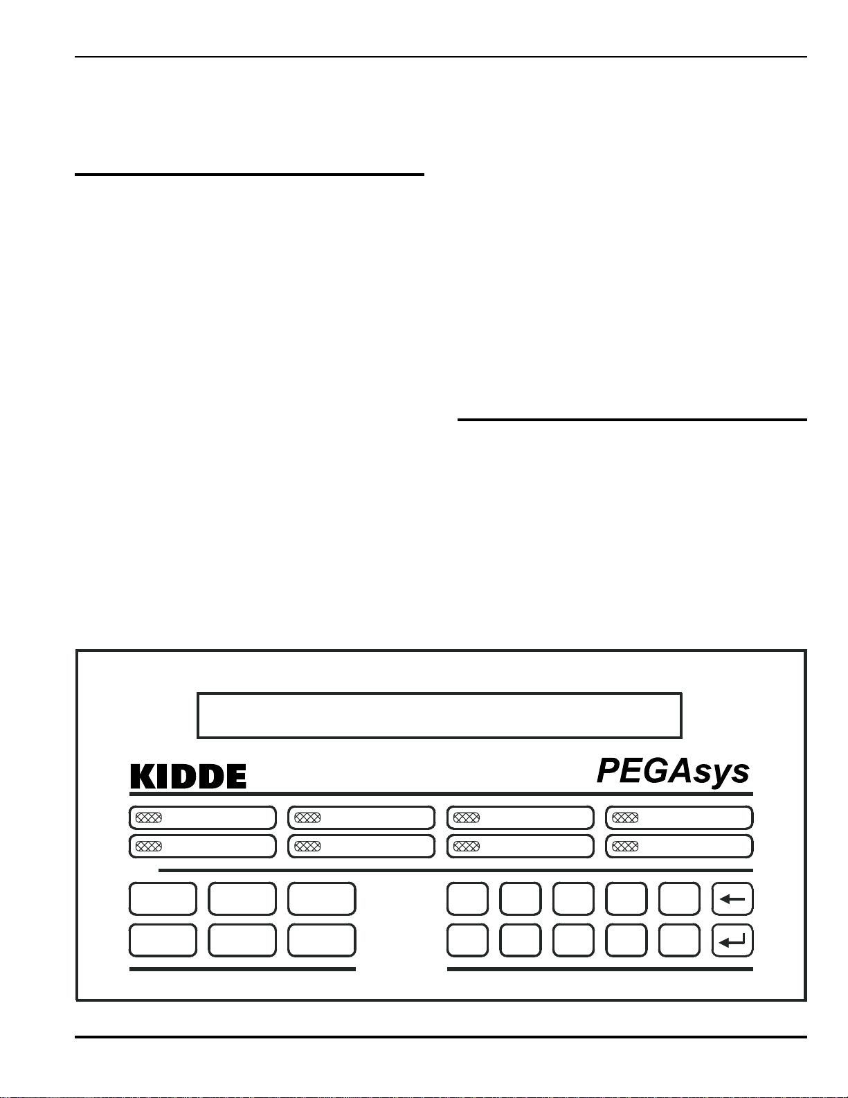
2-2 CONTROLS AND INDICATORS
The control and indicators of the PEGAsys system are located
on the display panel, shown in Figure 2-1. The display panel is
mounted on top of the CCM. To gain access to the CCM, the
panel door must be open. Table 2-1 lists controls and indicators
for the display unit, giving name and functional description.
2-2.1 LCD Display
The display panel contains an 80-character (2X40) alphanumeric display. This LCD display is used to present system status. In the procedure section of this chapter there will be several
System Status
POWER ON
GROUND FAULT
ACKLDGE RESET
SCROLL DRILL
SILENCE
DRILL
ALARM
PREALARM
Figure 2-1. System Front Panel
2-1
TROUBLE
CPU ERROR
14
6
SUPERVISORY
SILENCE
2
7890
3
5
August 199976-100016-001
Page 24

PEGAsys
Intelligent Suppression Control/Fire Alarm System
simulated LCD display readouts. The LCD display readouts
will be used to aid users in the operation of the system.
2-2.2 Audible Device
The Display Panel also contains an audible device which generates two separate audible tones, one for alarms and one for
troubles. This device sounds continuously when a new alarm
condition is received until the condition is acknowledged. It also
sounds intermittently when a trouble, supervisory, or pre-alarm
condition is received until the condition is acknowledged.
2-2.3 Control and Indicator Description
Refer to Table 2-1 for complete description of controls and indicators.
2-3 SYSTEM SECURITY
The PEGAsys system provides three distinct levels of program
protection, as required by UL Standard 864. The user can only
access the system by entering a valid password. Typical valid
passwords consist of three or four characters but may be up to
eight characters in length.
2-3.1 Levels of Security
The three security levels are: Level One, Level Two, and System Manufacturer. The highest security level is reserved for the
system manufacturer. System owner is level one, system installer is level two. Passwords consist of numeric characters (0
- 9) which allows access from the integral keypad of the CCM.
Alphanumeric characters can only be used with the PCS program and if used they will lock out any possible entry using the
CCM keypad to gain entrance to the menus.
If alphanumeric passwords are necessary for a particular application, it is recommended that the Level One password be numeric and the Level Two password be alphanumeric so as to
allow the user to retrieve system information (system information lists) and also prevent a user from changing any programmed system parameters.
2-3.2 Default Passwords
The PEGAsys system provides protection from unauthorized
entry to the system menus by utilizing two levels of default passwords, level one and level two. This feature provides two separate passwords which increases the security of the system.
Default passwords are set when the system is shipped from
Kidde. These default passwords are:
Level One = 987
Level Two = 1865
These default passwords are valid until other passwords are
programmed into the system.
2-3.3 Entering Passwords
The password entry procedure is listed below:
a. Verify that the system status is displayed.
b. Press 0 (zero) key. Verify that the display reads:
PLEASE ENTER PASSWORD
c. Type in three or four digit password into keypad. Ensure a
pound sign (#) appears for each key pressed.
NOTE: Use the default password, if a new password has not
been set.
d. Press the return (
↵↵
↵) key. Verify that the display reads:
↵↵
1:ISOLATE 2:LIST
3:SET 4:TEST
2-4 SYSTEM POWER-UP
The following step-by-step procedure is for initial power-up of
the CCP.
a. Perform the installation check-out procedure in Chapter 7
of this manual.
b. Set the circuit breaker for the CCP power to ON. Verify that
the display reads "Main Processor Power On" and that the
CPU ERROR indicator is lit. Ensure that the audible device
is buzzing continuously.
c. Press the display module reset switch. Verify that the CPU
ERROR indicator is extinguished and the audible device is
silenced.
d. Verify that the display reads as follows:
MAIN PROCESSOR
POWER ON
e. After ten seconds, verify that the display reads as follows:
RXTX NON-MONITORING TROUBLE ON
RXTX1
NOTE: For multi-loop systems only. The above and below RX/
TX messages will repeat themselves for each RX/TX
module installed in the system. The above message
will be displayed while the system is initializing itself.
This initialization can take up to 90 seconds.
To clear the below RX/TX message use the AutoLearn
function from the menu function or upload the
configuration from the PCS program. If using PCS
software, verify that the correct number of RX/TX loops
are enabled in the Loops Topic of the configuration file
prior to uploading.
RX/TX 1 NOT REGISTERED ON
RX/TX LOOP 1
f. Verify that the POWER ON and TROUBLE indicators are
lit.
g. Connect the backup batteries to the CCP in accordance to
the procedure in Chapter 7.
h. Press the ACKLDGE pushbutton. After approximately one
minute the display will momentarily read :
RXTX NON-MONITORING TROUBLE OFF
i. Verify the display reads the incorrect time and date.
j. Set time and date as follows:
(1) Press 0 (zero) key. Verify that the display reads:
PLEASE ENTER PASSWORD
(2) Type in the default 1st level password (987).
(3) Press the return (↵) key. Verify that the display reads:
August 1999 76-100016-001
2-2
Page 25

Intelligent Suppression Control/Fire Alarm System
Table 2-1. Control and Indicators
DELNOITCNUF
NOREWOP
PEGAsys
nehW.rewoptupniCAgniviecersimetsysehttahtsetacidni,detanimullinehW
ehtdna)noitidnocelbuort(derruccosaheruliafrewoptupniCAnasetacidni,ffo
.noitidnocybdnatsyrettabaotdehctiwssahmetsys
MRALA
ELBUORT .metsysehtnistsixenoitidnocelbuortasetacidni,detanimullinehW
YROSIVREPUS
TLUAFDNUORG
MRALA-ERP
RORREUPC
ECNELIS .decnelisneebevahstuptuoelbiduA/langiSehtsetacidni,detanimullinehW
HCTIWSNOITCNUF
EGDELWONKCA
tupninaybdetroperneebsahnoitidnocmralanasetacidni,detanimullinehW
.ecived
aybdetroperneebsahnoitidnocyrosivrepusasetacidni,detanimullinehW
.tupniyrosivrepusrofdemmargorpecivedtupni-metsys
enilCDV42ehtnodetcetedneebsahtluafdnuorgasetacidni,detanimullinehW
.-/+rehtieyalpsidlliwDCLehT.rotinomylppusrewopehtyb
ekomsfoleveladesnessahrotcetedtaehroekomsasetacidni,detanimullinehW
.tnioptesmrala-erpehtsdeecxehcihwtaehro
otstluafedmetsysehT.deliafsaherawtfosMCCsetacidni,detanimullinehW
.sutatslangiSlareneG/mralAenoZ
-nonroftessiecivedtupnifiFFOmralA(NOmralAnaretfadesserpnehW
secnelisti,deruccosahnoitidnocNOmrala-erpro,yrosivrepus,elbuorT)gnihctal
ro,"YROSIVREPUS","ELBUORT","MRALA"ehT.rezzubelbiduas'lenapeht
sahnoitidnocehttahtetacidniotydaetsswolgrotacidniDEL"MRALA-ERP"
ehtdnuoserotlenapehtesuaclliwsnoitidnoctneuqesbuS.degdelwonkcaneeb
.ecneuqesevoba
ECNELIS
TESER
LLORCS
LLIRD
)0-1(DAPYEKCIREMUN .metsysunemehtotninoitamrofnimetsysdnadrowssapretneotesU
ECAPSKCAB .seirtnegnorwtcerrocotdnametsysunemehttixeotesU
NRUTER .metsysunemehtgnisunehwyekretnEehtsadesU
langismetsysehtsecnelisti,mralAtnerrucgnigdelwonkcaretfadesserpnehW
rotacidni"ECNELIS"ehT.elbaecnelissademmargorpneebevahhcihwstuptuo
ehtgnisserP.decnelisneebevahstuptuolangisehttahtetacidniotsetanimulli
.sutatstuptuOyaleRehttceffetonseodhctiws"ECNELIS"
eht,deraelcdnadegdelwonkcaneebevahsmralaevitcallaretfadesserpnehW
:metsys
srotcetederiw4rewopotdesustuptuoCDV42yrailixuasteseR
.snoitidnocmraladehctalllasteseR
.etatslamronriehtotsyalerllasnruteR
.yalpsidlausivehtno"teseRmetsyS"syalpsiD
.ffosrotacidni"MRALAENOZ"dna"MRALA"ehtsnruT
esuaclliw,noitidnocyrosivrepusro,elbuort,mralaevitcanagniruddesserpnehW
tonlliwnoitidnocmralAehT.)s(reffubtneveevitcaehthguorhtllorcsotDCLeht
wollatonlliwnoitidnocyrosivrepuS.deweivebotselbuortroyrosivrepuswolla
.deweivebotreffubselbuorteht
langisllaetavitcalliwmetsyseht,sdnocesevifrofdlehdnadesserpnehW
.noitavitcallirdrofdemmargorpneebevahhcihwstuptuo
2-3
August 199976-100016-001
Page 26

PEGAsys
Intelligent Suppression Control/Fire Alarm System
1:ISOLATE 2:LIST
3:SET 4:TEST
(4) Type in 3111 on the keypad. Verify that the display
reads:
SYSTEM TIME (AM/PM)
ENTER THE TIME _ _ : _ _ (HH:MM)
(5) Type in the time (HH=hours 0-12 and then MM=minutes
0-59). Press the return key. Verify that the display reads:
SYSTEM TIME (AM/PM)
1:AM 2:PM
(6) Type in appropriate selection (1 for AM or 2 for PM).
NOTE: If there has been a mistake in the entered data, press
the backspace key as many times as required to get to
the mistake, then re-enter data from that point.
k. The power-up procedure is complete at this point. The sys-
tem is now ready for loop device registration and programming which is covered in this chapter.
2-5 SYSTEM MENUS
PEGAsys has a built-in menu structure. This menu structure
has been implemented to aid users with system operating functions. The following paragraphs describe the menu structure,
accessing the menu, exiting the menu and menu functions. Figure 2-2 shows the system's Level One menu structure. Figure
2-3 shows the system's Level Two menu structure.
2-5.1 Menu Structure
The PEGAsys menu structure consists of a main menu, and
multiple sub-level menus. The sub-level menus may also contain multiple sub-level menus. The main menu displays after
you enter a valid password. You can also access the Top Level
menu from any sub-level menu at almost anytime by pressing
the backspace key located on the keypad.
NOTE: The top level menu may not be available by using the
backspace key while certain types of programming are
being performed.
It is possible to access a previous higher level menu from a
lower level menu by pressing the backspace key.
The choices of available sub menus after a valid password has
been entered, correspond to the security level password that
has been entered.
The main menu for the 1
security level is:
st
level, 2nd level, and Manufacturer
1:ISOLATE 2:LIST
3:SET 4:TEST
2-5.3 Exiting the System Menus
To exit the system's menus, perform the following steps:
a. Press the backspace key as many times necessary to reach
the top level menu, shown in the top of the next column:
1:ISOLATE 2:LIST
3:SET 4:TEST
b. Press the backspace key. Verify that the system returns to
standby. The display should read:
SYSTEM STATUS NORMAL HH:MM MM-DD YR
40 CHARACTER CUSTOM MESSAGE
NOTE: When exiting the system menus, if the system is normal
the display panel should show the time and date as
shown in the above step.
2-5.4 Menu Functions
Tables 2-2 through 2-5 list and provide a brief description of all
functions that you can perform using the PEGAsys system’s
menus. In addition, the tables provide the security access level
and a keystroke formula for each function. The keystroke formula is a sequence of numbers you enter via the system’s keypad to access a particular function. These formulas provide the
path from the main menu to the desired function. Formulas are
provided for each access level. After you enter the formula, some
of the functions require you to press the return key to start implementing the function.
Most functions will require that you enter additional data to implement the function, such as a device address or desired alarm
threshold.
2-5.4.1 ISOLATE MENU FUNCTION
The isolate menu function (Table 2-2) permits the operator to
isolate field devices and output modules. Isolating any device
immediately places the system in a trouble condition, and initiates an audible trouble alarm and a printout with the time, date,
and device isolated. The feature is typically used to temporarily
isolate auxiliary devices during a system test.
2-5.4.2 LIST MENU FUNCTION
The list menu function (Table 2-3) permits the operator to list
various system parameters. All lists are real time actual system
conditions which are displayed and printed with the time and
date.
2-5.4.3 SET MENU FUNCTION
The set menu function permits the operator to program various
system parameters within the system. A few examples are shown
in Table 2-4.
Any one of the basic functions listed in a main menu can be
selected by pressing the numeric key of the system’s keypad
which corresponds to the desired function. (Example: To select
the LIST function from the main menu, press the 2 key on the
system keypad.) You also select lower level functions from sublevel menus using the numeric keys.
2-5.2 Accessing the System Menus
Perform the steps in Paragraph 2-3.3.
August 1999 76-100016-001
2-5.4.4 TEST MENU FUNCTION
The test menu function, shown in Table 2-5, allows the operator
to test individual or a group of field devices. On command, a
detector or contact input device can be tested, and results will
be printed and displayed at the Central Control Panel. The Test
procedure in the device is activated by imposing a signal within
the device that will cause an alarm output. The Control Panel
verifies that an alarm output is generated and reports “Test
Result OK” for each device.
2-4
Page 27
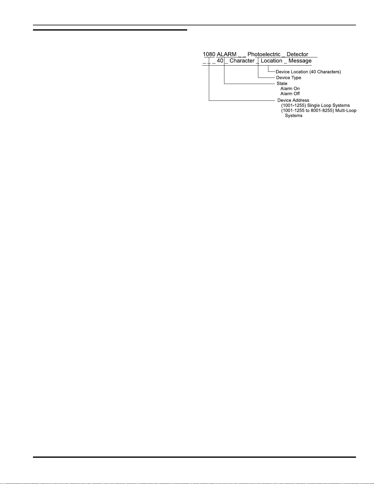
Intelligent Suppression Control/Fire Alarm System
2-6 MODES OF OPERATION
The PEGAsys system has four modes of operation. Each mode
has different indications and action required. The following Paragraphs describe each mode, indications and action if required.
2-6.1 Normal Standby Mode
This is the typical mode of the system. In this mode, no alarm,
trouble, or supervisory conditions exist in the system. The system display will show the time, day of the week, and date. For
example:
SYSTEM STATUS NORMAL 11:06 AM_05-04-90
40_CHARACTER_CUSTOM_MESSAGE
The system provides an option which allows the System Status
Normal message to be replaced with a display of battery charging voltage and current for the system standby batteries. For
example:
PS01_26.0 V_0.10_A_ _ _ _ _11:06 AM_05-04-90
40_CHARACTER_CUSTOM_MESSAGE
The green AC POWER LED will be illuminated to indicate that
the system’s main power source is normal.
NOTE: In the Normal Standby Operation state, it is possible
for the 80-character display to show data other than
the time, day of date. This occurs when the system
menus are being accessed either locally or remotely
through one of its serial ports. This condition will be
indicated by the menu selections being displayed on
the display panel being illuminated.
In the Normal Standby Mode, no indicating LED’s will be illuminated other than the “AC POWER.”
2-6.2 Active Alarm Mode
The system enters an alarm mode if a device (or devices) has
detected an alarm condition, such as smoke / heat above the
alarm threshold level. There are two types of alarms which can
occur:
Device Alarm
An alarm in which a device has communicated the alarm status
properly to the Central Control Panel, by providing the alarmed
device address for indication to the operator.
Zone Alarm
An alarm condition detected by one or several devices, but which
cannot be reported by a specific device due to a malfunction in
communications between the system and the alarmed device(s).
This is a redundant feature to increase system reliability and is
called Failsoft Mode.
NOTE: A device can signal a zone alarm to the system during
some communication failures.
2-6.2.1 ALARM MODE INDICATIONS
The following indicates the system is in its alarm mode of operation.
a. The red “ALARM” LED will be illuminated and there will be
a continuous audible signal by the system buzzer at the
panel.
PEGAsys
b. The 80-character display will cycle between all currently
active alarms. Example:
NOTE: If the alarm is a zone alarm, the Device Address “1000
- 8000” will be displayed depending on which RX/TX
module detects the zone alarm.
b. The outputs which have been previously programmed for
activation upon alarm by the specific devices will be turned
on. (Example: Signal audible signaling devices, control relays for HVAC shutdown or elevator recall.)
2-6.2.2 ALARM MODE USER ACTION
The following steps should be performed when the system is
set into alarm.
a. Press the display panel’s ACKLDGE pushbutton to acknowl-
edge the displayed alarm condition. The 80-character display will continue to cycle between any remaining alarms
which have not been acknowledged. The “ACKNOWLEDGE” switch must be operated once for each alarm received at the panel.
b. Once all current alarms have been acknowledged, the alarm
indicating circuits (audible devices) can be silenced by operating the “SILENCE” switch.
c. After all of the current alarms have been acknowledged,
verify that the display reads: XXX ALARMS REMAIN. The
“XXX” representing the total of all active alarms. All active
alarms can be viewed on the display by pressing the scroll
pushbutton.
NOTE: The first 64 alarms will only be displayed. Subsequent
alarms over the initial 64 will not be displayed, even
when any or all of the first 64 alarms clear. However,
all alarms regardless of total will be processed in the
EOC. For a complete list of active alarms access the
event buffer menu using the CCM keypad.
d. Any subsequent alarms will cause the alarm audible cir-
cuits to resound. Each additional alarm must be acknowledged before the alarm indicating circuits can be silenced.
e. When a device goes out of alarm, the display will indicate
the device address and an alarm off (AOF) message (nonlatching mode). Example:
1080 AOF_ _ _ _PHOTOELECTRIC DETECTOR
40_CHARACTER_LOCATION_MESSAGE
NOTE: If the alarm is a zone alarm, the address “1000-8000”
will be displayed, indicating that active device(s) in
failsoft mode in the zone have gone out of alarm.
f. Each device which goes out of alarm must be acknowl-
edged with the ACKLDGE pushbutton (non-latching).
2-5
August 199976-100016-001
Page 28
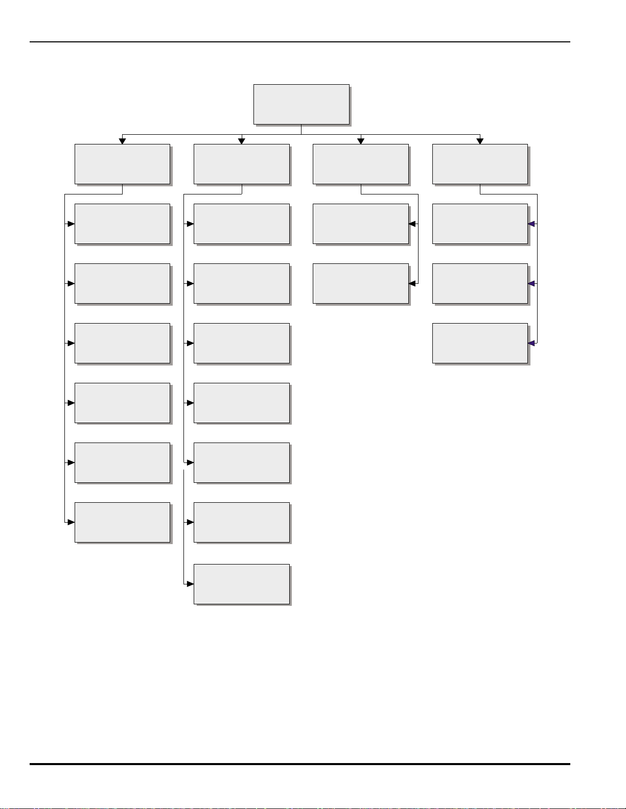
PEGAsys
Intelligent Suppression Control/Fire Alarm System
Please Enter Password
1:ISOLATE
1:LoopDevices
2:SignalOutputs
3:RelayOutputs
4:Release Outputs
2:LIST
1:IsolatedDevices/Outputs
2:EventBuffer
3:Detector Level
4:Active Events
3:SET
1:Time - Date
2:PrinterControl
4:TEST
1:Lamp Test
2:Loop Device(Alarm Test)
3:Battery Test
5:City TieOutput
6:Digital I/O
5:Programming
6:Assignments
7:Voltages
Figure 2-2. Level One Menu Structure
August 1999 76-100016-001
2-6
Page 29
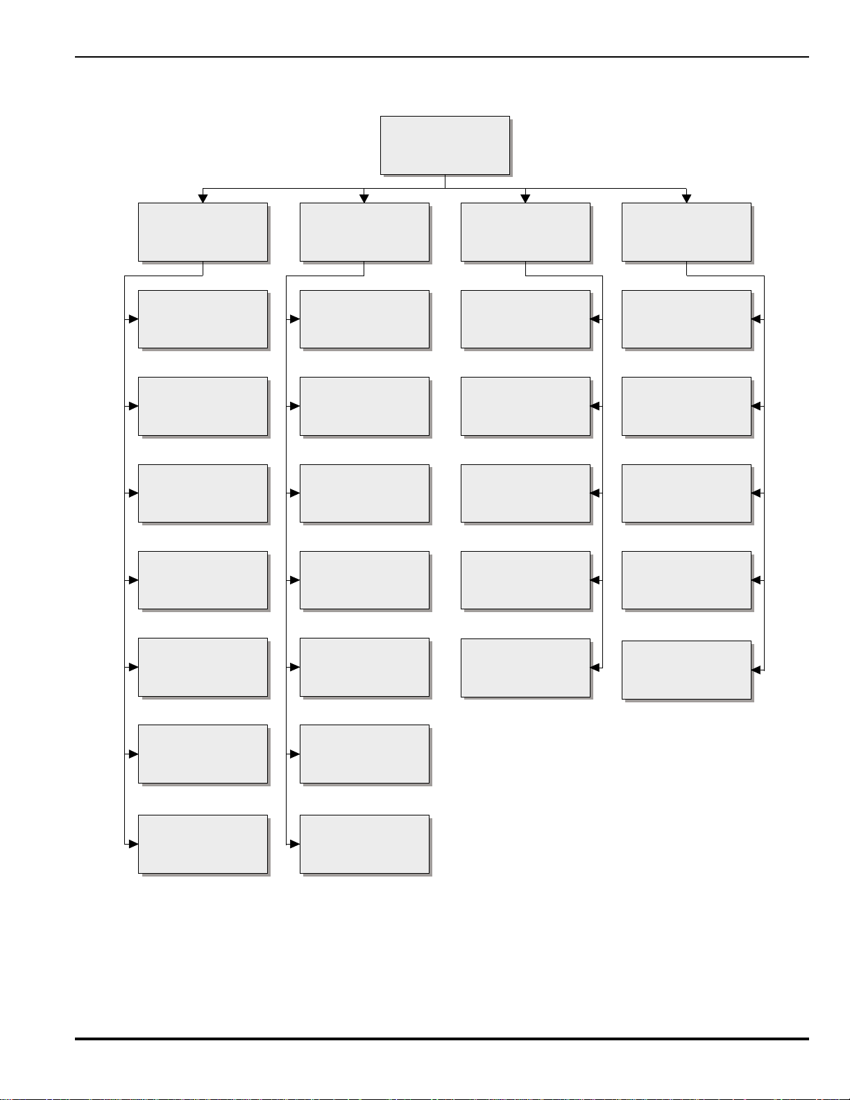
Intelligent Suppression Control/Fire Alarm System
PEGAsys
Please Enter Password
1:ISOLATE
Devices
1:Loop
2:Signal Outputs
Outputs
3:Relay
4:Release Outputs
2:LIST
1:Isolated Devices/Outputs
2:EventBuffer
3:DetectorLevel
4:Active Events
3:SET
1:Time - Date
2:Printer
3:Devices
4:Programming
4:TEST
1:Lamp Test
2:Loop Device(Alarm Test)
3:Battery Test
4:WalkTest
5:CityTieOutput
6:Digital I/O
6:GlobalI/O
7:Global
6:GlobalI/O
5:Programming
6:Assignments
7:Voltages
5:Unused
Figure 2-3. Level Two Menu Structure
2-7
5:Alarm Simulation Test
August 199976-100016-001
Page 30

PEGAsys
Intelligent Suppression Control/Fire Alarm System
Table 2-2. Isolate Menu Function
noitcnuFnoitpircseDalumroF
eciveDpooLetalosI sserddaybUCRnaetalosi-eD/etalosI1-1M/2/1
tuptuOlangiSeludoMO/IetalosI sserddaybtiucrictuptuoeludomlangisaetalosi-eD/etalosI1-2-1M/2/1
tuptuOlangiSesaeleReludoMO/IetalosI .sserddaybtuptuolangiseludomesaeleraetalosi-eD/etalosI2-2-1M/2/1
tuptuOlangiSMCCetalosI tuptuolangisMCCAetalosi-eD/etalosI3-2-1M/2/1
tuptuOyaleReludoMO/IetalosI sserddaybtuptuoyalereludomO/Iaetalosi-eD/etalosI1-3-1M/2/1
tuptuOyaleRMCCetalosI tuptuoyalerMCCetalosi-eD/etalosI2-3-1M/2/1
tuptuOesaeleReludoMO/IetalosI sserddatuptuoybtuptuoesaelertneganaetalosi-eD/etalosI1-4-1M/2/1
tuptuOesaeleRtnegAMCCetalosI
tuptuOeiTytiCetalosI sserddatuptuoybeludomeityticetalosi-eD/etalosI5-1M/2/1
tuptuO/tupnIlatigiDetalosI sserddaO/Iybtuptuo/tupnilatigidetalosi-eD/etalosI6-1M/2/1
stupnIetalosIlabolG seludomO/I;secivedpooltupnimetsysllaetalosi-eD/etalosI1-7-1M/2
stuptuOetalosIlabolG seludomO/Ituptuometsysllaetalosi-eD/etalosI2-7-1M/2
sserdda
tuptuoMCCybtuptuoesaelertneganaetalosi-eD/etalosI
2-4-1M/2/1
sseccA
leveL
NOTE: 1 = LEVEL ONE, 2 = LEVEL TWO, M = MANUFACTURER LEVEL
Table 2-3. List Menu Function
noitcnuFnoitpircseDalumroF
seciveDpooLdetalosItsiLdetalosierahcihwseciveDpooLllatsiL1-1-1-2M/2/1
seludoMO/IdetalosItsiLdetalosierahcihwseludomO/IllatsiL1-2-1-2M/2/1
stuptuoMCCdetalosItsiLdetalosierahcihwstuptuoMCCllatsiL2-2-1-2M/2/1
)stnevE
yrotsiHtnevEtsiL
snoitidnoC
margorPCOEtsiLsenilmargorpCOEtsiL1-5-2M/2/1
margorPCTRtsiLsenilmargorpCTRtsiL2-5-2M/2/1
llA(reffuByrotsiHtnevEtsiL
)stnevEfoegnaR(reffuB
rotceteDelgniSatsiL leveltaeh/ekomsemitlaers’rotceteddetcelesasyalpsiD 1-3-2M/2/1
leveLrotceteDtsiL
)s(mralAevitcAtsiL.)s(mralametsysevitcallatsiL1-4-2M/2/1
yrosivrepuSevitcAtsiL
CDV9eciveDpooLtsiL
levelylppusrewop
etad
.leveltneserpdna
noitidnoCelbuorTevitcAtsiLsnoitidnocelbuortmetsysevitcallatsiL3-4-2M/2/1
sesserddAeciveDpooLtsiL metsysehtotnideretsigersecivedpoolllatsiL1-6-2M/2/1
sesserddAeludoMO/ItsiL metsysehtotnideretsigerseludomO/IllatsiL2-6-2M/2/1
sleveLegatloVeniLCPtsiL ecivedpooldeificepshcaetaslevelegatlovenilCPstsiL1-7-2M/2/1
reffubmorfseirtneyrotsihtnevededrocerllastsiL1-2-2M/2/1
ybseirtneyrotsihtnevefoegnarelbatcelesresuastsiL
stnioptesmraladnamrala-erpsrotcetedmetsysllastsiL
.snoitidnocyrosivrepusmetsysevitcallatsiL2-4-2M/2/1
levelylppusrewoptlov9ecivedpooldeificepsstsiL2-7-2M/2/1
NOTE: 1 = LEVEL ONE, 2 = LEVEL TWO, M = MANUFACTURER LEVEL
sseccA
leveL
2-2-2M/2/1
2-3-2M/2/1
August 1999 76-100016-001
2-8
Page 31

Intelligent Suppression Control/Fire Alarm System
PEGAsys
Table 2-4. Set Menu Function
noitcnuFnoitpircseDalumroF
emiTmetsySteSemitmetsystesotresuswollA 1-1-3M/2/1
etaDmetsySteSetadmetsystesotresuswollA 2-1-3M/2/1
)I+V(yrettaBfoyalpsiDteS
.tnerruc
dnaegatlovgnigrahcyrettabfoyalpsidtesotresuwollA
retnirPlanretnIteS noitcennocretnirplanretniroftropelbanE 1-1-2-3M/2/1
retnirPlanretnIelbasiD noitcennocretnirplanretniroftropelbasiD 2-1-2-3M/2/1
retnirPlanretxEteS noitcennocretnirplanretxeroftropelbanE 1-2-2-3M/2/1
retnirPlanretxEelbasiD noitcennocretnirplanretxeroftropelbasiD 2-2-2-3M/2/1
sserddAeciveDteS.sserddaecivedegnahcotresuswollA 1-3-3M/2
rotceteDnoitazinoIteS
ytivitisneS
sgnittes
rotceteDcirtceleotohPteS
ytivitisneS
sgnittes
rotceteDlamrehTteS
ytivitisneS
sgnittes
mraladnamralaerProtcetednoitazinoItsujdaotresuswollA
mraladnamralaerProtcetedcirtceleotohPtsujdaotresuswollA
mraladnamralaerProtcetedlamrehTtsujdaotresuswollA
sseccA
leveL
3-1-3M/2/1
1-2-3-3M/2
2-2-3-3M/2
3-2-3-3M/2
seciveDretsigeR noitarugifnocmetsysotnisecivedpoolretsigerotresuswollA 3-3-3M/2
seciveDretsigeR-eD
.snoitarugifnoc
metsysmorfsecivedpoolretsiger-edotresuswollA
4-3-3M/2
lortnoCknilB gniknilbDELrotcetedelbasidotresuswollA 5-3-3M/2
edoMthgiN/yaDteS .noitcnufyadrofrotcetedelbaneotresuswollA 1-1-4-3M/2
sdoirePthgiN/yaDteSsdoirepthgiN/yaDtesotresuswollA 2-1-4-3M/2
edoMyaDetavitcAedomyaDetavitcaotresuswollA 3-1-4-3M/2
drowssaPlevelts1teSdrowssaplevelts1tesotresuswollA 1-2-4-3M/2
drowssaPleveldn2teS.drowssapleveldn2tesotresuswollA 2-2-4-3M/2
margorPCTRelbanE noitcnufotenilmargorpCTRelbaneotresuswollA 1-3-4-3M/2
margorPCTRelbasiD .gninoitcnufmorfenilmargorpCTRelbasidotresuswollA 2-3-4-3M/2
edoMnraeLotuAteS noitcnuFnraeLotuAehtetavitcaotresuswollA 4-4-3M/2
noitacifireVmralAteS
.srotcetedfoegnarrosrotcetedlaudividnirof
doirepemitdnanoitcnufnoitacifirevmralaehttesotresuswollA
5-4-3M/2
noitcnuFSAPteS secivedrofecneuqesmralaevitisopehttesotresuswollA 6-4-3M/2
goLtnevEraelC seirtnereffubyrotsihtneveraelcotresuswollA 7-4-3M/2
elbanEegdelwonkcAlabolG erutaeFegdelwonkcAlabolGehtselbanE 1-8-3M/2
elbasiDegdelwonkcAlabolG erutaeFegdelwonkcAlabolGehtselbansiD 2-8-3M/2
NOTES: 1. For installation in the state of California, Alarm Verification Time must not exceed 30 seconds.
2. 1 = LEVEL ONE, 2 = LEVEL TWO, M = MANUFACTURER LEVEL
2-9
August 199976-100016-001
Page 32

PEGAsys
Intelligent Suppression Control/Fire Alarm System
Table 2-5. Test Menu Functions
noitcnuFnoitpircseDalumroF
sseccA
leveL
tseTpmaLytilanoitcnufsDELmetsystsetotresuelbanE1-4M/2/1
tseTeciveDpooL
srotcetedfopuorg
rorotcetedafotsetcinortcelenaetavitcaotresuswollA
1-2-4M/2/1
tseTyrettaB yticapacyrettabyfirevottsetyrettabaetavitcaotresuswollA3-4M/2/1
tseTklaWelbanE tseTklaWotsecivedfoegnarayficepsotresuswollA1-4-4M/2
tseTklaWelbasiDedomtsetklawelbasidotresuswollA2-4-4
tseTnoitalumiSmralA
NOTE: 1. WARNING: The Alarm Simulation Test must be used with care. When activated the Alarm Simulation Test (AST)
processes pre-programmed outputs which are related to the activated (simulated) input device. Before using AST ensure
that any associated outputs are disconnected or isolated to prevent unexpected outputs (releases, signals or shutdowns).
2. 1 = LEVEL ONE, 2 = LEVEL TWO, M = MANUFACTURER LEVEL
For latching mode: To return the system to normal, press
the RESET button once. If powering 4-wire detector from
the PEGAsys, the reset button will need to be pushed once
to reset the detector and once to reset the panel to a normal condition.
g. In a non-latching operation once all alarms have cleared,
the display will read: NO ACTIVE ALARM REMAINS. At
this time, the system may be reset by operating the RESET
pushbutton.
h. When the system is properly reset, the display will show
the System Status Normal message, time, day and date.
The preceding will happen if no active troubles or
supervisories are present, in which case the “Active
Troubles” or “Active Supervisories” message will be displayed.
2-6.3 Active Supervisory Trouble Mode
The system enters supervisory trouble mode when it detects an
abnormal condition on the system that has been defined to be a
much higher priority than a common trouble. This type of trouble
is usually assigned by the installer/designer to monitor critical
parts of the system.
2-6.3.1 SUPERVISORY TROUBLE MODE INDICATION
The following indicates the system is in the supervisory trouble
mode of operation.
a. The yellow SUPERVISORY and TROUBLE LEDs will be
flashing at a 1 second rate and there will be a pulsing buzzer
at the CCM. This audible is distinctively different than an
alarm signal pattern at the CCM.
b. The 80 character display will cycle between all currently
active supervisory troubles. Example:
2-6.3.2 SUPERVISORY TROUBLE MODE USER ACTION
The following steps should be performed when the system is
set into supervisory trouble mode of operation:
a. To silence the supervisory trouble audible signal, all cur-
rent supervisories must be acknowledged by pressing the
ACKLDGE push button. This will silence the system buzzer.
b. When all supervisory trouble conditions have been acknowl-
edged, the 80 character display will read: XXX ACTIVE
SUPERVISORY TROUBLES REMAIN. XXX representing
the total number of active supervisory troubles. All current
trouble conditions can be viewed on the display by pressing the scroll push button.
c. As each supervisory trouble condition is cleared, the dis-
play will read one less active trouble until all supervisories
are clear. When all active supervisory troubles have been
cleared, the SUPERVISORY and TROUBLE LEDs will be
extinguished and the 80 character display will show the
Standby Message. (For example: "System Status Normal")
NOTE: The system has the option to acknowledge both
supervisory and common troubles on a global basis.
The panel by default will require that each trouble be
acknowledged individually. However, if the installer
wishes to enable this function it can be done by
accessing the "set" menu option using the CCM
keypad. Refer to Table 2-4 for more information on
stepping through the menus to enable and disable
otstupnifopihsnoitalerdemmargorpyfirevotrellatsniswollA
.evitcaerastuptuogniyfirevdnastupnignitavitcaybstuptuo
5-4M/2
August 1999 76-100016-001
2-10
Page 33

Intelligent Suppression Control/Fire Alarm System
PEGAsys
the Global Acknowledge function. With global
acknowledge a total of 30 troubles can be
acknowledged at one time.
2-6.4 Active Trouble Mode
The system enters trouble mode when it detects an abnormal
condition which may prevent proper operation or display a
prealarm condition. (Example: loss of communications with a
smoke detector.) Refer to Appendix G for a complete list of
trouble conditions.
2-6.4.1 TROUBLE MODE INDICATIONS
The following indicates the system is in its trouble mode of
operation.
a. The yellow TROUBLE LED will be flashing at a 1 second
rate and there will be a pulsing panel buzzer at the CCP.
This audible signal is distinctively different than the alarm
audible signal.
b. The 80 character display will cycle between all currently
active troubles and prealarms. Example:
2-6.4.2 TROUBLE MODE USER ACTION
The following steps should be performed when the system is
set into the trouble mode of operation:
a. To silence the trouble audible signal, all current trouble
conditions must be acknowledged by pressing the
ACKLDGE pushbutton. This will silence the system buzzer.
b. When all trouble conditions have been acknowledged, the
80-character display will read: XXX ACTIVE TROUBLES
REMAIN. XXX representing the total number of active
troubles. All current trouble conditions can be viewed on
the display by pressing the scroll pushbutton.
NOTE: The first 300 troubles (supervisory or common) on a
Single-Loop will be displayed only. Subsequent troubles
or supervisories will not be displayed even if any or all
300 troubles clear. However, all of the active troubles
or supervisories will be processed and entered into the
event buffer. For a complete listing of all troubles and
supervisories over the initial 300, access the event
buffer using the event buffer using the CCM keypad.
For the Multi-Loop the first 2100 troubles or
supervisories will be displayed. Subsequent troubles
or supervisories over the first 2100 will not be displayed
even if any or all 2100 troubles or supervisories clear.
However, all troubles or supervisories regardless of the
total will be processed and entered into the event buffer.
For a complete listing of all active troubles and
supervisories, access the event buffer through the CCM
keypad.
c. As each trouble condition is cleared, the display will read one
less active trouble until all troubles are cleared. When all active troubles have been cleared, the “TROUBLE” LED will be
extinguished and the 80-character display will show the
standby message (For example: "System Status Normal").
NOTE: The system has the option to acknowledge both
supervisory and common troubles on a global basis.
The panel by default will require that each trouble be
acknowledged individually. However, if the installer
wishes to enable this function it can be done by
accessing the "set" menu option using the CCM
keypad. Refer to Table 2-4 for more information on
stepping through the menus to enable and disable the
Global Acknowledge function. With global acknowledge
a total of 30 troubles can be acknowledged at one time.
2-7 PRINTING OPERATION
In addition to the LCD display, the PEGAsys system information can be viewed using the Printer port of the CCM. For detailed information pertaining to connecting a RS-232 peripheral
device, see the Chapter 7, Paragraph 7-18.
When the printer port is enabled and a serial printer is attached
the system will print out all status change information and any
system information lists that the user would request from the
system using the integral keypad.
Serial-type annunciator devices may be connected to the printer
port to provide graphical LED annunciator type indications to
building occupants. Contact Kidde application engineering for
compatible annunciator vendors.
2-8 SYSTEM PROGRAMMING
The PEGAsys fire alarm system incorporates two unique programming languages that are easy to understand and use.
These two versatile programming languages, Event Output
Control (EOC) and Real Time Control (RTC), can accommodate most any fire alarm control logic application. Programming
the system is accomplished by a personal computer via a system interface cable.
The two programs are constructed by the system Engineer/Installer using the PEGAsys Configuration Software (PCS) program which is Windows™ based. The PCS program allows the
user to configure, verify, upload, download, edit, retrieve, store
and print the entire system configuration program. Refer to the
PCS user’s guide (P/N 76-014) for further details.
2-8.1 EOC Programming
The Event Output Control (EOC) program logically combines the
system’s input devices with the system's output devices. The program consists of sequentially numbered lines of equations containing input addresses, output addresses and logic operators.
When an input becomes true (Active), the system processes the
EOC program and activates any associated outputs as programmed.
2-11
August 199976-100016-001
Page 34

PEGAsys
Intelligent Suppression Control/Fire Alarm System
EXAMPLE:
The simplest event output control (EOC) equation would be:
Input = Output
A basic equation with one or more inputs would be :
Input Operator Input = Output
The system normally processes the EOC from left to right. However,
in equations with parenthesis the contents of the parenthesis are
executed first. Refer to the PCS user’s guide (76-014) for further
details.
2-8.1.1 LISTING EOC PROGRAMMING
The system's Event Output Control (EOC) program can be listed
out using either the owner's or installer's menu functions. To list the
systems EOC programming:
a. Access PEGAsys system menus by:
(1) Press 0 (zero) key. Verify that the display reads:
PLEASE ENTER PASSWORD
(2) Type in the Level 1 or Level 2 password.
(3) Press the return (↵) key. Verify that the display reads:
1:ISOLATE 2:LIST
3:SET 4:TEST
b. Select the list EOC program by typing the function formula, 2-5-
1.
The system will then list all lines of the Event Output Control programming on the LCD and any attached printer.
2-8.2 RTC Programming
The RTC program language permits outputs to be controlled by the
system’s real time clock. Outputs may be programmed to occur on
an hour, day, week and month time control basis. Alarm and Prealarm
threshold levels of all or individual detectors can be increased or decreased in sensitivity (within UL limits) under RTC control. The RTC
programming also provides the ability to control RCU relays, I/O
module Relays and smoke detector pre alarm and alarm set points.
The program consists of sequentially numbered lines each containing control object, control content, time, date and day of week. For
further details refer to the PCS user’s guide.
2-8.2.1 LISTING RTC PROGRAMMING
The RTC program can be listed out using either the owners or installers menu functions. To list the RTC programming:
a. Access the PEGAsys system menus by:
(1) Press 0 (zero) key. Verify that the display reads:
PLEASE ENTER PASSWORD
(2) Type in the Level 1 or Level 2 password.
(3) Press the return (↵) key. Verify that the display reads:
1:ISOLATE 2:LIST
3:SET 4:TEST
b. Select the list RTC program by typing the function formula, 2-5-
2.
The system will then list all lines of the Real Time Control program-
ming on the LCD and any attached printer.
2-8.2.2 ENABLE/DISABLE RTC PROGRAM LINE NUMBERS
Each line number of the RTC Program is automatically enabled when
entered into the system. Once a line number in the RTC Program
has been disabled using the procedure below, the line will be ignored
by the RTC Program until enabled. To enable a line number which
has been previously disabled follow the below procedure selecting
"ENABLE" in step b.
a. Access the PEGAsys system menu’s by:
(1) Press 0 (zero) key. Verify that the display reads:
PLEASE ENTER PASSWORD
(2) Type in the Level 1 or Level 2 password.
b. Select the set RTC program by typing the function formula, 3-4-
3. Verify the display reads:
1:ENABLE 2:DISABLE
c. Select the desired choice and press return. Verify the display
reads:
RTC LINE NUMBER _ _ _
d. Type the three digit line number and press the return key.
e. You may continue with another RTC line or press backspace
key to cancel this function.
2-8.3 Types of Inputs and Outputs
The PEGAsys has various input and output devices/modules which
are discussed in the following paragraphs:
2-8.3.1 SYSTEM INPUTS
Devices which are classified as system inputs are smoke detectors,
heat detectors, and addressable contact monitors (alarm, trouble,
abort, waterflow, manual alarm, manual release, supervisory, and
normal). Refer to the PCS user’s (76-014) guide for further details.
2-8.3.2 REMOTE CONTROL UNIT (RCU)
The RCU input and output devices, which are connected to the RX/
TX loop(s), are specified in EOC programming by the devices four
digit address.
2-8.3.3 RX/TX LOOPS
The system specifies the RX/TX loop controller using its loop number followed by three zeros (1000 for RX/TX 1) in single loop systems and (1000 - 8000) in multi-loop systems. The specifier (1000
-8000) will appear in cases when trouble conditions are present on a
particular RX/TX loop controller (i.e., a PC Line Short on RX/TX 1 would be displayed as "RX/TX PC Line Short Loop 1").
RX/TX loop (zone) alarms occur if a loop device alarm initiates under
one of the following conditions:
• Failed communications between the CCM and RX/TX module
(Trouble Condition)
• Failed RX/TX processor. (Trouble Condition)
• Failed input circuit of RCU device.
An alarmed input device on the RX/TX (in FailSoft mode) can only
activate EOC programming if the RX/TX zone is used as a programmed input (ZA1=1000, ZA2=2000, ZA8 = 8000, etc.).
2-8.3.4 SYSTEM OUTPUTS
Devices which are classified as system outputs are CCM - signals and relays (programmable / non programmable); I/O modules - signal outputs, relay outputs, agent release outputs, release
August 1999 76-100016-001
2-12
Page 35

Intelligent Suppression Control/Fire Alarm System
PEGAsys
signal outputs, city tie outputs and digital I/O module outputs; Loop
devices - addressable relay output module.
2-8.3.5 SYSTEM I/O MODULES
The Input/Output modules which the systems support are Signal
Outputs, Relay Outputs, Agent Release (agent & signal) outputs
and the City Tie output.
2-8.4 Addressing I/O Modules
The I/O modules include: Signal Audible, Relay Output, Agent
Release Output, City Tie output and the power supply module.
I/O modules refer to any I/O module which installs into the optional I/O mother board with exception of the power supply
module(s). The I/O modules communicate with the CCM over
the I/O bus.
Each module has inputs or outputs which can be individually
addressed. The I/O address consists of two alphabetic and two
numeric characters which define the module type, address and
I/O circuit number. The I/O module address scheme is shown
below.
SG1:3
I/O Circuit Number (1-4),
See note 1.
Module Address (1-8),
See note 2.
Module Type,
See note 3.
• SG - Signal / Audible Output
• RY - Relay Output
• CT - City Tie Output
• AR - Agent Release Output
• RS - Release Signal Output
• PS - Power Supply Monitor Module
NOTES:
1. The I/O modules vary in amount of inputs and outputs. Refer
to section one “component description” for thorough descriptions of options.
2. The PEGAsys system can support a total of 16 I/O modules
for single loop and 23 I/O modules for multi-loop, 8 maximum of
any one type.
3. Power supply monitors only need an address, they have no
need for an output number.
The I/O module address is set using the three dip switches contained on each PCB assembly, each module uses different numbered switches for module address assignment. The address
is set during the installation procedure by placing the switches
into the correct position. Refer to the appropriate figure in Appendix I for the particular module you are working with and the
addressing matrix. For a functional description of each module,
refer to Chapter 3.
The switches would be set for each type of module in order. For
example signal modules would be addressed 1 -8 if there were
eight in the system, relay modules would be addressed 1 - 8 if
there were eight in the system, and the same holds true for the
remaining modules with the only exception being the City Tie module there can only be one of these modules in a system at any
time.
2-8.5 Registering I/O Module Assignments
I/O modules are registered into the system configuration through
the use of the PCS program. The installer would configure all
modules in the PCS program file and then upload this file to the
system which would then internally verify the existence of the specified modules. For further details on I/O module registration refer
to the PCS user’s guide.
Added RX/TX Modules in the multi-loop systems are automatically registered by the CCM upon system power-up.
2-8.5.1 LISTING I/O MODULE ASSIGNMENT
All I/O modules which are programmed into the system configuration may be listed out with the use of either the owners or
installers menu functions.
a. Access the PEGAsys system menu’s by:
(1) Press 0 (zero) key. Verify that the display reads:
PLEASE ENTER PASSWORD
(2) Type in the Level 1 or Level 2 password.
(3) Press the return (↵) key. Verify that the display reads:
1:ISOLATE 2:LIST
3:SET 4:TEST
b. Select the list I/O address assignments by typing the func-
tion formula, 2-6-2.
The system will then list all of the registered I/O module addresses on the LCD and any attached printer.
2-8.6 Addressing RCUs
RCUs refer to all devices which connect and operate from the
RX/TX PC (power/communications) Line. These devices include
SmartOne smoke detectors, SmartOne heat detectors, addressable contact input monitors, and addressable output contact
modules.
Each device has a three digit numeric address. This address is
stored in the non-volatile EEPROM memory of the device. The
system address is defined by the CCM by these three digits
and a fourth digit representing the RX/TX channel number.
There are three ways to address the RCU (Loop) devices.
• The RCUs can be addressed using the Hand Held Programmer (P/N 74-200013-001). This optional unit provides
a convenient means of addressing RCUs without using the
CCM.
• The user may address the devices individually on the system by performing the procedure listed below.
To address RCUs using the “SET RCU Address” menu function
each unaddressed RCU’s must be connected to the RX/TX PC
line one at a time. Perform the following steps for each RCU:
a. Access the PEGAsys system menu’s by:
(1) Press 0 (zero) key. Verify that the display reads:
PLEASE ENTER PASSWORD
(2) Type in the Level 2 password.
(3) Press the return (↵) key. Verify that the display reads:
2-13
August 199976-100016-001
Page 36

PEGAsys
Intelligent Suppression Control/Fire Alarm System
1:ISOLATE 2:LIST
3:SET 4:TEST
b. Select the set RCU address function by typing the function
formula, 3-3-1. Verify that the display reads:
PRESENT LOOP DEVICE ADDRESS _ _ _ _
NOTE: All new addressable devices have an address of zero
(000).
c. Enter the present RCU address and press return
pushbutton. The system will display the following:
TARGET LOOP DEVICE ADDRESS _ _ _ _
d. Enter the desired address for the RCU / Detector, press
return. The system will now change the RCU address if
different than previously noted.
The 40 character owner location message cannot be entered
using the system keypad. The owners location message can
only be entered by use of the PCS program and uploaded into
system memory.
2-8.7 Registering RCUs
Registration is where the device address is joined with the device information in the system's memory. Device information is
comprised of; Device type, Device Messages and Device settings.
There are four ways to register the RCU (Loop) devices on to
the system.
• The user may register the devices individually on the system
• Register all pre-addressed RCU’s at once using RCU (Loop
Devices) registration function
• Register all pre-addressed RCU’s using the Autolearn function, which sets all devices at default values and any system alarm input activates all system outputs. If pre-addressed
devices are used, multiple devices can be attached and registered to the system all at one time using either the Autolearn
or RCU Registration function.
• RCU’s can also be registered into the system by using the
PCS program. The installer would specify each RCU to be
connected to the system and then upload the system configuration file to the system and then the system would supervise each device specified. Refer to the PCS user’s guide
for further details on RCU registration.
tion would be to attach all pre addressed loop devices to the PC line
of the RX/TX module. Power up the system (if it is not already running). As the loop devices power up they will begin to communicate
with the RX/TX module. The CCM will recognize the loop devices as
not being not registered and raise a trouble for each not registered
(TBL NR) device attached. When the register RCU function is enabled the CCM will prompt the user to enter a range of loop device
addresses to register as valid system devices. At the conclusion of
the register function the CCM will display the total amount of devices
registered.
The AutoLearn function works much the same as the registration
function, where it will automatically enter the devices which it can
identify on the PC line of the RX/TX as not being registered into
system configuration memory.
During both the Autolearn and RCU Registration procedures the
CCM will automatically register the loop devices into memory and
also set each device to default settings (Sensitivity levels and
Input reporting) for the particular device. The CCM will also set the
default operation of the CCM outputs (MP01, MP02, MP03 and
MP04). Any system alarm received after this time will cause all
the CCM outputs (MP01 - MP04) to activate.
Optionally, if the I/O motherboard and I/O modules have been
installed, the PCS program will need to be used to configure the
system for use with the I/O modules. Procedures for registering I/
O modules are provided in the PCS Users Guide (See “Addressing I/O Modules”).
2-8.7.1 DETECTOR REGISTRATION
SmartOne smoke and heat detectors would be registered on to
the system in the same fashion as the RCU’s explained in the
previous section. The only other information which requires selecting is detection devices application, the alarm and pre-alarm,
levels and latching or non-latching. There are three specific applications for smoke detector use: Open Area, Open Area (High
Air Flow) and Duct. The smoke and heat detectors pre-alarm and
alarm set points are adjusted only when necessary if the user
desires the set points to be different from the default values for
each detector type.
The detectors will use the default values unless otherwise programmed. To adjust the set points for the detectors, refer to Chapter
5 Setting and Adjusting Smoke and Heat Detector Sensitivities.
The 40 character owner location message cannot be entered
using the system keypad. The owners location message can
only be entered by use of the PCS program and uploaded into
system memory.
1004
001-255 = Device Address (registered)
000 = Device Address (un addressed/
un registered)
RXTX Loop Number
1 for single Loop Systems,
1-8 for Multi-Loop Systems
Example: RCU 1032 represents device 32 on RX/TX loop 1.
Connecting an unregistered RCU address (address 000) to the
RX/TX will result in a not registered trouble (TBL NR) indicating
that the control panel has communicated with the device and identified the device as being unregistered.
Procedures for registering RCU devices using the register RCU func-
August 1999 76-100016-001
2-8.7.2 ADDRESSABLE CONTACT MONITOR
REGISTRATION
The addressable contact monitor are registered on to the system
in the same fashion as the RCU’s explained in the previous section. The system will by default, set the response of the device
activation to alarm. During system configuration using the PCS
program the following choices are allowed - Alarm, Trouble, Abort,
Supervisory, Manual Alarm, Manual Release, WaterFlow or Normal. The following table describes the allowable selections for
the input RCU and their EOC relationships.
Contact monitor RCUs are also registered into the system by
using the PCS program. The installer would specify each Contact
Monitor RCU to be connected to the system and then upload the
system configuration file to the system and then the system would
supervise each device specified. Refer to the PCS user’s guide
2-14
Page 37

Intelligent Suppression Control/Fire Alarm System
PEGAsys
for further details on RCU registration.
1: Alarm
Active input initiates an alarm at the central control
panel and is latched in the EOC until the system is
reset after alarm has cleared.
2: Trouble
Active input initiates a trouble at the central control
panel, but does not latch EOC programming and will
self restore upon deactivation.
3: Abort
Active input initiates an abort condition at the central
control panel. This will delay agent release if countdown has begun. It does not latch EOC program and
will self restore upon deactivation. There are 4 styles
of abort available for the device.
4: Waterflow
Active input initiates a waterflow alarm condition at the
central control panel and is latched in EOC program
until reset. Signal outputs will be inhibited from being silenced.
5: Manual Alarm
Active input initiates a manual alarm condition at the
central control panel, latches in EOC program until
reset.
6: Manual Release
Active input initiates a manual release condition at the
central control panel, causes instant release of programmed output, latches in EOC program until reset
7: Normal
Active input initiates a momentary display but does not
latch in EOC program, self restores.
8: Supervisory
Active input initiates a supervisory trouble at the central control panel, but does not latch the EOC, and will
self-restore upon deactivation.
The 40 character owner location message cannot be entered
using the system keypad. The owners location message can
only be entered by use of the PCS program and uploaded into
system memory.
2-8.7.3 REMOTE RELAY REGISTRATION
The addressable contact output device is registered in the
same fashion as the previous RCU's.
Contact Output RCU’s can also be registered into the system
by using the PCS program. The installer would specify each
Contact Output RCU to be connected to the system and then
upload the system configuration file to the system and then the
system would supervise each device specified. Refer to the PCS
user’s guide (76-014) for further details on RCU registration.
The 40-character owner location message cannot be entered
using the system keypad. The owners location message can
only be entered by use of the PCS program and uploaded into
system memory.
a. Access the PEGAsys system menus by:
(1) Press 0 (zero) key. Verify that the display reads:
PLEASE ENTER PASSWORD
(2) Type in the Level 1 or Level 2 password.
(3) Press the return (↵) key. Verify that the display reads:
1:ISOLATE 2:LIST
3:SET 4:TEST
b. Select the List RCU address function by typing the function
formula, 2-6-1. Verify that the display and any attached printers list all registered RCU addresses.
2-8.7.5 UN-REGISTERING RCUs
The system provides the capability to remove a single device or
group of devices from the system configuration. This function
removes the device address from the system memory but leaves
the address in the device intact. Performing this operation will
cause the system to generate a trouble NR (Not Registered) for
any devices which remain connected to the RX/TX PC line.
Removal or disconnection of the device(s) from the PC line will
clear the trouble condition(s) on the system.
This function would be used during a system retrofit where some
devices may be desired to be removed from the system temporarily during a building renovation and then reattached after renovations are complete. This feature is very efficient because the
device maintains its address information which speeds device
reregistering after the renovations.
To perform the device un-registering operation perform the following:
a. Access the PEGAsys system menus by:
(1) Press 0 (zero) key. Verify that the display reads:
PLEASE ENTER PASSWORD
(2) Type in the Level 1 or Level 2 password.
(3) Press the return (↵) key. Verify that the display reads:
1:ISOLATE 2:LIST
3:SET 4:TEST
b. Select the set RCU De-Registration function by typing the
function formula, 3-3-4. Verify that the display reads:
DEVICE DE-REGISTRATION
DEVICE FROM_ _ _ _TO_ _ _ _
c. Enter the desired RCU address(s) and press return. The
display will read the following in response to verify the device de-registration:
DEVICE DE-REGISTRATION
XX DEVICES DE-REGISTERED
d. Verify that the display changes to the device menu after 5
seconds. The backspace key can be pressed to return to
the main menu.
e. To reregister RCU devices, perform the procedure which is out-
lined in the RCU registration paragraph in this chapter.
2-8.7.4 LISTING ALL REGISTERED RCUs
All RCUs registered on the system can be listed using either the
owners or installers menu function. To list all registered RCUs
2-15
August 199976-100016-001
Page 38

PEGAsys
Intelligent Suppression Control/Fire Alarm System
(THIS PAGE INTENTIONALLY LEFT BLANK)
August 1999 76-100016-001
2-16
Page 39

Intelligent Suppression Control/Fire Alarm System
CHAPTER 3
FUNCTIONAL DESCRIPTION
3-1 INTRODUCTION
This chapter provides a functional description of the devices/
modules used in the PEGAsys system configuration. Each functional description covers one of the blocks shown in the overall
block diagram, Figure3-1.
3-2 BLOCK DIAGRAM
The PEGAsys system is divided into seven functional blocks as
follows:
PEGAsys
• Central Control Module
• Display Module
• RX/TX Module
• I/O Module
• RCUs (Field Devices)
• Power Supply Module
As described in Paragraph 1-1.2, the system comes in two configurations the single-loop system and multi-loop system. The
above devices/modules for both configurations are shown in
the Overall Functional Block Diagrams, Figures 3-1 and 3-2.
Each device/module is described in detail in Paragraph 3-3.
AC Line
Battery
Backup
AC Line
Battery
Backup
Display
Module
Power
Supply
Display
Module
Power
Supply
Central
Control
Module
24 VDC
I/O Bus
24 VDC
I/O Bus
24 VDC
Figure 3-1. Overall Block Diagram, Single-Loop System
Optional
I/O
Motherboard
RX/TX CCM
Comm
I/O Bus
24 VDC
Central
Control
Module
24 VDC
I/O Bus
I/O Bus
24 VDC
RX/TX 24 VDC
RX/TX CCM
Comm
Multi-Loop I/O
Motherboard
RX/TX CCM
Comm
24 VDC
I/O Bus
24 VDC
Receiver/
Transmitter
Module
(RX/TX)
Optional
I/O Module
Receiver/
Transmitter
Module
(RX/TX)
Up to 8 RX/TX
Modules
Optional
I/O Module
Power/Comm
Line
Power/Comm
Line
RCU's
(Field Devices)
RCU's
(Field Devices)
Figure 3-2. Overall Block Diagram, Multi-Loop System
3-1
August 199976-100016-001
Page 40

PEGAsys
To External
Printer
CCM Reset
Button
To Remote PC For
Programing
24VDC From
Power
Supply
To RX/TX
Loop
Controller
To I/O Modules and
Power
Supplies
Display
Port
Proc.
Port
Display Reset
24VDC From
Power
Supply
See Note 2
Note 1: The trouble relay
contacts
are shown in the
unpowered
state.
Note 2: Jumpers JP1-JP4 are
used
to configure MP01 to be
signaling
or releasing (default)
outputs.
Refer to Dwg. No.
06-235443-001,
in Appendix I,
for
further details.
Intelligent Suppression Control/Fire Alarm System
3-3 FUNCTIONAL DESCRIPTIONS
The functional descriptions will describe each device or module depicted in Figures 3-1 and 3-2.
3-3.1 Central Control Module
The Central Control Module (CCM) is available in two versions,
P/N 76-100008-501 for single-loop and P/N 76-100008-600 for
multi-loop. Figure 3-3 contains the main central processing unit,
real time clock, watch dog timer and RS-232 serial communication input/output ports. The CCM controls the operation and
supervision of all the system modules and software within the
PEGAsys system. It receives loop device data from the RX/TX
module, processes the data based on pre-programmed instructions and transmits output commands to the output modules,
field devices and display module(s).
The CCM provides two RS-232C serial ports for programming
and monitoring the PEGAsys system. These ports accept 6wire RJ-12 modular connectors. The PCS program would be
used to interface to the system for programming purposes. A
multilevel password scheme protects the system from unauthorized access.
The real time clock provides the CCM with the ability to display
the current time & date on the system LCD and control the system with time based programming.
Internal diagnostics enhance the troubleshooting ability of the
system, examples: microprocessor failure, memory failure, RS232 port troubles, etc..
Two individually programmable signal output circuits (MP1 &
MP2) provided can be used for signaling devices (horns, strobes,
bells) and allow up to 2.0 amps of 24 VDC power. One of the
two outputs is programmed for releasing solenoid type suppression equipment (Agent and Sprinkler type systems).
Two individually programmable relay outputs (MP3 & MP4) are
provided on the CCM for controlling building functions during
alarm occurrences. These relay outputs are activated through
the EOC programming which allows system inputs to be related to system outputs. Each of these relays have Form C style,
rated at 1A, 30VDC.
One non programmable trouble relay is supplied which is normally powered (24 VDC) and will transfer on any system trouble,
supervisory, pre-alarm and complete power off condition. Form
C contact rating 1A at 30VDC. Refer to DWG. No. 06-235443001 in Appendix I for further installation details.
An event history buffer is provided on the CCM which will store
1024 entries for single-loop and 6100 entries for multi-loop of
system event information and allow the operator to retrieve this
information for review of system operation. The PCS program
provides the ability to download, store and print all or a portions
of the Event History Buffer.
CCM Reset
Button
Display
Port
SOUNDER 1
A
B
REP 1
+
+
-
-
TB4
JP4
JP3
SW1
JK1
PRINT
DISP
PORT
PORT
To External
Printer
PLG2
JK1
JK2
REP 2
TB5
SOUNDER 2
A
+
-
VOLTFREE RELAYS
B
1
2
NC C
C
NO NO
TB1
NC
TB2
See Note 2
See Note 2See Note 2
+
-
V/F RELAY
FAULT
NO C
TB3
See Note 1
NC
JP1
JP2
TB6
FLT
SUPPLY
EARTH
PORT
BT1
JK3
P.C .
1
PLG1
24V5V
DISPLAY
PLG2
0V
0V
5V
To Remote PC For
Programing
Proc.
Port
Display Reset
SW1
PLG6
PLG3
JK2
JK3
PLG1
PLG2
Figure 3-3. Central Control Module, Details
JK5
I/O
PORT
To I/O Modules and
JK4
FLT
0V
24V
Power Supplies
RX/TX
PORT
To RX/TX
Loop Controller
24VDC From
Power Supply
24VDC From
Power Supply
TB6
Note 1: The trouble relay
contacts are shown in the
unpowered state.
Note 2: Jumpers JP1-JP4 are
used to configure MP01 to be
signaling or releasing (default)
outputs. Refer to Dwg. No.
06-235443-001, in Appendix I,
for further details.
August 1999 76-100016-001
3-2
Page 41

Intelligent Suppression Control/Fire Alarm System
PEGAsys
3-3.2 Receiver/Transmitter Module (RX/TX)
The RX/TX functions as the hardware & software interface between the loop devices and the CCM. Each installed RX/TX
module continually monitors all addressable devices for alarm
and trouble conditions. Each device is capable of initiating and
sending alarm and trouble messages to the RX/TX module to
which it is connected.
See Note
The RX/TX receives control requests from the CCM and establishes communications with the loop devices. The RX/TX receives status changes from the loop devices and reports these
changes to the CCM. The RX/TX shown in Figure 3-4 is capable of communicating with up to 255 intelligent devices and
complies with the Signaling Line Circuit (SLC) requirements of
NFPA-72 Style 4, 6 & 7. Style 4 initiation circuit wiring will permit “T” tapping or branch circuitry. Style 7 requires the use of
optional loop isolator devices.
STYLE 6 Signal Line Circuit, with Loop Isolator
Zone 1
Zone 2
Loop
Isolator
Zone 3
Loop
Isolator
76-100005-001
RX/TX
CPU Reset
PC Line Normal
CPU Reset
PC Line Reset
See Note
Note: Refer to jumper table on Dwg. 06-235371-002 in appendix I
STYLE 6 Signal Line Circuit
1
2
3
4
STYLE 4 Signal Line Circuit
1
2
3
4
Loop Isolator
for Style 7
(74-200012-001)
Loop
Isolator
4321
RET
RET
24V
LOOP ISOLATOR
Mounted to RX/TX
74-200012-001
Isolator
24V
RX/TX
Note: Each zone can consist of 30 loop devices
between loop isolators
STYLE 7 Signal Line Circuit
Loop
Loop
Isolator
Zone 2
Loop
Isolator
Isolator
Zone 1
See Note
Loop
Isolator
4321
RET
RET
24V
24V
LOOP ISOLATOR
Mounted to RX/TX
74-200012-001
RX/TX
NOTE: Adjacent loop isolators must be within 20ft. Of a device with wiring in conduit
to be in accordance with NFPA Style 7 requirements.
Loop
Loop
Isolator
Zone 3
Loop
Isolator
Figure 3-4. Receiver/Transmitter Module, Details
3-3
August 199976-100016-001
Page 42

PEGAsys
Intelligent Suppression Control/Fire Alarm System
3-3.3 Power Supply/Charger Assembly, Rev. A
This power supply assembly was provided with earlier systems.
Information is being provided for service purposes only. The
power supply/charger assembly, Figure 3-5 (P/N 76-100009-
001) is comprised of a printed circuit board (PCB) mounted on
a AC / DC switching power module. The switching power provides 4 amps of 24 VDC power from the 120 / 240 VAC input
power. The PCB assembly is a microprocessor based unit which
provides the system with
• Battery charging (up to 33 AH) and supervision Low Voltage Battery cutoff at 19VDC
• AC power supervision
• 24 VDC supervision
• Battery load test
• 24 VDC ground fault detection (+/-)
• Trouble relay that transfers upon any power supply trouble
or power off condition (Relay shown in the unpowered state)
• Auxiliary 24 VDC outputs (programmable for switched or
unswitched configurations)
The auxiliary 24 VDC outputs rated at 1 Amp each and can be
used to power 4 wire type detection devices such as smoke,
flame and gas detectors which must be sized properly to stay
within output current limits.
The power supply/charger assembly is addressable and communicates with the CCM over the I/O bus.
The power supply/charger assembly provides terminal connections for an auxiliary power module. This module comes with 2
different wiring harnesses, as follows:
• P/N 76-100009-002 is supplied with a 36" harness that is
meant to connect a main power supply/charger assembly
to the auxiliary power module in the main cabinet.
• P/N 76-100009-003 is supplied with an 8" harness to mount
a main power supply/charger assembly to an auxiliary power
module in a expansion enclosure.
The addition of an auxiliary power module to the main power
supply/charger assembly will provide an additional 4 amps of
current and make the total available current of 8 amps for this
assembly. The system can support up to 8 main power supply/
charger assemblies with the capability of adding an auxiliary
power module to each one to provide a maximum available current of 64 amps. Each additional power supply/charger assembly (P/N 76-100009-001) would need to have a separate address
to operate in the system. The auxiliary power module would
share the same address as the main power supply/charger assembly that it is connected to. Refer to drawing number 06235443-003, in Appendix I, for further installation details.
Figure 3-5. Obsolete Power Supply/Charger Assembly (Revision A), Details
August 1999 76-100016-001
3-4
Page 43

Intelligent Suppression Control/Fire Alarm System
PEGAsys
3-3.4 Power Supply/Charger Assembly, Rev. C.
• Battery charging (up to 99 AH) and supervision
• Low Voltage Battery cutoff at 19VDC
• AC power supervision
• 24 VDC supervision
• Battery load test
• 2 auxiliary 24 VDC outputs, programmable for switched or
unswitched configuration
• Trouble relay that transfers upon any power supply trouble
or power off condition (Relay shown in the unpowered state)
The power supply/charger assembly (P/N 76-100009-010) provides terminal connections for an auxiliary power module. This
module is available with two different wiring harnesses, which
follow:
• P/N 76-100009-002 is supplied with a 36" harness that is
meant to connect a main power supply/charger assembly
to the auxiliary power module in the main cabinet.
• P/N 76-100009-003 is supplied with an 8" harness to mount
a main power supply/charger assembly to an auxiliary power
module in a expansion enclosure.
The addition of an auxiliary power module to the main power
supply/charger assembly will provide an additional 4 amps of
current and make the total available current of 8 amps for this
assembly. The system can support up to 8 main power supply/
charger assemblies with the capability of adding an auxiliary
power module to each one to provide a maximum available current of 64 amps. Each additional power supply/charger assembly (P/N 76-100009-010) would need to have a separate address
to operate in the system. The auxiliary power module would
share the same address as the main power supply/charger assembly that it is connected to. Refer to drawing number 06235443-003, in Appendix I, for further installation details.
NOTE: The Rev. C. Power Supply/Charger assembly can be
distinguished from the Rev. A. version by the large heat
sink on the right side of the unit.
CAUTION: THE VOLTAGE FOR THE TWO BATTERIES IN SERIES MUST
BE GREATER THAN 22 VDC BEFORE CONNECTION TO THE PANEL.
POWER LIMITED TO 1.5 A DC
POWER LIMITED TO 1.5 A DC
Figure 3-6. Power Supply/Charger Assembly (Revision C), Details
3-5
TWO (2) SEALED
LEAD-ACID
BATTERIES
August 199976-100016-001
Page 44

PEGAsys
Intelligent Suppression Control/Fire Alarm System
3-3.5 Multi-Loop I/O Motherboard
The multi-loop I/O motherboard assembly, P/N 76-100017-001,
is an assembly which can accept any combination of 9 modules consisting of up to 8 RX/TX modules and provide connections for up to 7 I/O module circuit board assemblies. The ML
motherboard is mounted to standoffs on the back of the main
system enclosure. It distributes the system 24 VDC power, CCMRX/TX communications modules and I/O bus communications
to the I/O modules. The I/O bus communications are provided
by a RJ-12 (flat phone cable) style connection. A single RJ-12
connection connects the ML motherboard to the CCM for RX/
TX communications. The 24 VDC is provided by the system
power supply via a 2 conductor wiring harness connected to a
terminal block (TB9) is distributed through terminal blocks (TB1TB8) for connection on RX/TXs. The 24 VDC provided by the
system power supply via 2 conductor wiring connected to terminal block TB-11 is distributed through I/O bus slots for powering I/O modules.
The RX/TX module communicates to the CCM via the multiplexer
located on the motherboard. The CCM identifies each of the installed RX/TX modules by the RS-232 connection on the
motherboard. The table below lists each RX/TX communication
connection located on the motherboard and the loop number and
addresses assigned to the connected module. Refer to Drawing.
No. 06-235443-012, in Appendix I, for installation details.
Table 3-1. Multi-Loop I/O Motherboard Connectors
ROTCENNOCPOOLSSERDDA
1PJ1 5521-1001
2PJ2 5522-1002
3PJ3 5523-1003
4PJ4 5524-1004
5PJ5 5525-1005
6PJ6 5526-1006
7PJ7 5527-1007
8PJ8 5528-1008
Figure 3-7. Multi-Loop I/O Motherboard, Details
August 1999 76-100016-001
3-6
Page 45

Intelligent Suppression Control/Fire Alarm System
PEGAsys
3-3.6 Signal Output Module
The PEGAsys panel has the capacity for a maximum of 8 Signal Output modules, shown in Figure 3-8, thus providing 32 possible signal circuits. Each Signal Output module is equipped
with supervised 24 VDC outputs which can operate as Style “Y”
or Style “Z” indicating circuits. The module will allow for 4 Style
“Y” or 2 Style “Z” or a mix of 2 Style “Y” and 1 Style “Z”. Each
circuit is supervised for open, short and ground fault. The ability
to isolate individual outputs is accessed through the system
operator menu options.
The alarm output circuits are polarity reversing type, rated for
24 VDC signaling devices up to 2.0 Amp maximum per circuit.
Careful consideration of alarm strobe in-rush currents has been
made to help avoid any potential problems with the increased
power requirements in support of the wide range of the ADA /
UL 1971 signaling appliances in the marketplace. Refer to drawing number 06-235443-006 for installation details.
Reset Switch
SIGNAL AUD
Trouble LED
76-100003-001
Power for normal standby and alarm operation derives from either of two sources; 1) primary supply up to its capacity, or 2)
auxiliary power supply input. Provision for hardwire input of auxiliary power has been made through the use of hardwire connections between the auxiliary power supply and terminals 1 &
2 of the terminal block of the signal module. Output circuits are
listed for use in power limited applications.
Each circuit can be individually programmed via the PCS program for Continuous, Pulsed 60 or 120 BPM (March-Time) or
Coded (Temporal Pattern) operation. Relation between each
signal output and its input source shall be defined by the panel
EOC logic program. In Walk Test mode the signal output circuit(s)
shall sound the test signal if programmed properly. The walk
test signal will be a 1.0 second pulse, then off until the next
device is activated.
2 STYLE "Z"
5
-
CIRCUIT 1
6
Module Address
{
Assignment
10K EOR
10K EOR
10
11
12
-
7
+
8
+
9
-
-
+
+
CIRCUIT 3
Auxiliary Power
NotUsed
Sounder Circuits 1-4
Note 1: Refer to DWG. No. 06-235443-006,
in Appendix I, for Configuration
Jumper (W1-W8).
2: Cut Jumpers W9 & W10 when
Auxiliary Power Input is used to
remove module from RS-485
power bus..
3: Only 8 of this Type Module can
be used on the system. Refer
to Section 1-2.7, in Chapter 1,
for other limitations.
TB1
10K EOR
10K EOR
10K EOR
10K EOR
4 STYLE "Y"
See Note 2
{
10K EOR
1 STYLE "Z" AND 2 STYLE "Y"
5
-
6
10K EOR
10K EOR
-
7
+
8
+
9
-
10
-
11
+
12
+
CIRCUIT 4
CIRCUIT 1
CIRCUIT 3
2 STYLE "Y" AND 1 STYLE "Z"
5
-
6
-
7
+
8
+
9
-
10
-
11
+
12
+
CIRCUIT 1
CIRCUIT 2
CIRCUIT 3
CIRCUIT 4
10K EOR
10K EOR
10K EOR
5
-
6
-
7
+
8
+
9
-
10
-
11
+
12
+
CIRCUIT 1
CIRCUIT 2
CIRCUIT 3
Figure 3-8. Signal Output Module, Details
3-7
August 199976-100016-001
Page 46

PEGAsys
Intelligent Suppression Control/Fire Alarm System
3-3.7 Relay Output Module
The PEGAsys panel has the capacity for a maximum of 8 Auxiliary Relay Output cards for up to 32 relays. Each Auxiliary
Relay Output card (shown in Figure 3-9) is equipped with 4
Form C, dry contact relay outputs. The ability to isolate an individual relay output is accomplished through the system operator menu.
The auxiliary relays are rated for 2.0 Amp @ 30 VDC & 1.0 Amp
@ 120 VAC. Refer to Drawing. No. 06-235371-007, in Appendix I, for further installation details.
Each relay output can be individually programmed via the PCS
program for operation. Relation between each relay output and
its input source is defined by the panel EOC logic program. In
Walk Test mode the relay output circuit(s) will not operate when
the input device(s) under test are activated.
76-100004-001
RELAY
Note: A maximum of 8 Relay Output Modules can be used on the system. Refer to paragraph 1-2.7, in Chapter 1, for other limitations.
Figure 3-9. Relay Output Module, Details
August 1999 76-100016-001
3-8
Page 47

Intelligent Suppression Control/Fire Alarm System
rerutcafunaMsdioneloS
lawneF-eddiK
&005684
10005684
lawneF-eddiK181098
lawneF-eddiK494798
lawneF-eddiK571998
lawneF-eddiK036598
srerutcafunaMsuoiraV
&,E,D,B,AspuorGMF
G
sdioneloSrelknirpS
PEGAsys
3-3.8 Agent Release Output Module
The PEGAsys panel has the capacity for a maximum of 8 agent
release output modules, which provides up to 8 possible release
circuits and 24 maximum signal outputs on these modules.
Each Agent Release Output card is equipped with a 24V, supervised output which is programmable for solenoid-type discharge controls. The installer must select discharge control type
required during software configuration programming. The circuit shall be supervised for open or ground fault conditions. The
ability for individual release output isolate is provided through
the system operator menu.
Each card is equipped with supervised signaling outputs for 3
Style “Y” 24 VDC polarity reversing type indicating circuits. Each
signal circuit is supervised for open, short and ground fault conditions. The ability for individual output isolation is provided
through the system operator menu. Careful consideration of
alarm strobe in-rush currents has been made.
The agent release output circuit is rated for 24 VDC control
devices. Each release output can supervise and activate up to
two (2) solenoid control heads.
Table 3-2 details all devices with which the agent release module is approved for operation.
Table 3-2. Approved Release Output Devices
Power for standby and alarm operation of release and signaling
outputs shall derive from one of two sources; 1) primary supply up
to its capacity, or 2) auxiliary power supply input. Input of auxiliary
power is hardwired through terminals 1 & 2 on the modules terminal block. Output circuits are Listed for use in Power Limited applications. All signaling power is fully regulated.
Reset Switch
RELEASE
Trouble LED
1
TB1
12
}
76-100001-001
Auxiliary Power
Release Circuits
Signal Circuits
Note 1: Only a maximum of 8 of this type module can be used on the system.
Refer to paragraph 1-2.7, in Chapter 1, for other limitations.
2: W1 and W2 must be cut when the auxiliary power input is used.
Figure 3-10. Agent Release Output Module, Details
3-9
Module Address
Assignment
See Note 2
August 199976-100016-001
Page 48

PEGAsys
Intelligent Suppression Control/Fire Alarm System
3-3.9 City-Tie Module
The City Notification Card (Figure 3-11) provides connection and
operation for Local Energy, Shunt type Master Box and Reverse
Polarity styles of output. The output type is selected by choosing
which terminals terminate the field wiring. The module has an Amber LED to signify disconnect status. The ability for individual output isolate is provided through the system operator menu.
Local Energy-Type Output: Monitored output for trip circuit wiring and Master Box coil status (Set/Unset), current limited at
550 mA, 24 VDC. Monitored for open, short and ground fault.
Shunt-Type Output: Unsupervised contact rated at 5.0 Amp,
24 VDC resistive.
Reverse Polarity-Type Output: Unsupervised output for trip
circuit wiring only, current limited at 100 mA, 24 VDC.
Reverse Polarity output circuits are listed for use in Power Limited applications. Refer to Drawing. No. 06-235443-008 for further installation details.
The City Tie Module will operate during PEGAsys' “FailSoft”
mode. Any system alarm will cause the output to transfer.
In Walk Test mode the city notification outputs shall be disabled.
In addition, the output has provisions for manual disable or isolate through the operator menu function. The initiation of a walk
test will institute a system trouble causing the city tie output to
transfer to the trouble state.
76-100002-001
CITY TIE
Note: Only 1 City Tie Module can be connected to the system.
Figure 3-11. City Tie Module, Details
August 1999 76-100016-001
3-10
Page 49

Intelligent Suppression Control/Fire Alarm System
PEGAsys
3-3.10 Field Devices
The SmartOne Series of Intelligent Fire Alarm devices provide
the PEGAsys control system with smoke & heat detection, nec-
essary monitoring and control functions required by today’s advanced Fire Alarm systems. Each of the SmartOne devices
features an intrinsic microprocessor with 4K of nonvolatile
memory. Each device constantly monitors its surrounding environment and makes decisions in response to that information
then reports status as required to the control panel. Each loop
device communicates with the RX/TX module over the PC
(power/communications) line.
This “Distributed Intelligence” architecture allows each loop device to make decisions within the monitored area. This unique
utilization of processing power makes possible a system of loop
devices with greater capacity and flexibility than any typical addressable device system with centralized processing.
Each SmartOne device contains a status LED which blinks in
various patterns to indicate device status. The blink rates and
associated status levels are as follows:
Blink Rate Operation status
9 Second Rate Normal mode
2 Second Rate Alarm (activated)
Off (not blinking) Trouble condition
The following three paragraphs describe each type of available
detector. A typical detector is shown in Figure 3-12.
3-3.11 SmartOne Ionization Detectors
The SmartOne Ionization smoke detectors provide true distributed intelligence addressable microprocessor based smoke detection to the PEGAsys system. Model CPD-7052 is a dual
chamber analog ionization type detector which senses both visible and invisible smoke. A unique sensing chamber permits
360° smoke entry and response. Each detector is electronically
addressable and can be fully field programmed. Calibration, device address, pre-alarm & alarm sensitivity set points and drift
compensation algorithm are stored in each detectors non volatile memory.
SmartOne Ionization detectors have an unobtrusive low profile
look and are available using the following:
• Model CPD 7052 SmartOne Ionization Detector:
P/N 70-402001-100
3-3.12 SmartOne Photoelectric Detectors
The SmartOne Photoelectric smoke detectors provide true distributed intelligence addressable microprocessor based smoke
detection to the PEGAsys system. Model PSD-7152 is a analog photoelectric type detector which responds to a broad range
of smoldering and flaming type fires. A unique sensing chamber permits 360° smoke entry and response. Each detector is
electronically addressable and can be fully field programmed.
Calibration, device address, pre-alarm & alarm sensitivity set
points and drift compensation algorithm are stored in each
detector's nonvolatile memory.
SmartOne photoelectric detectors have an unobtrusive low profile look and are available using the following:
• Model PSD 7152 SmartOne Photoelectric Detector:
P/N 71-402001-100
Figure 3-12. Typical Detector
3-3.13 SmartOne Heat Detectors
The SmartOne heat detectors provide true distributed intelligence addressable microprocessor based heat detection to the
PEGAsys system. Model THD-7252 is a analog fixed temperature thermistor type detector which does not respond to rate of
rise conditions until its programmed set point is met. Unique
algorithms are used to compensate for heat rise without problems associated with false alarms due to elevated rates of rise
in ambient temperature.
A unique sensing chamber permits 360° heat entry and response. Each detector is electronically addressable and can
be fully field programmed. Calibration, device address, pre-alarm
& alarm sensitivity set points and drift compensation algorithm
are stored in each detector's nonvolatile memory.
SmartOne Heat detectors have an unobtrusive low-profile look
and are available using the following:
• Model THD 7252 SmartOne Heat Detector:
P/N 70-404001-100
3-3.14 Addressable Contact Input Devices
The PEGASYS Contact Monitor (P/N 70-407008-00X) allows
an installer the ability to interface typical NO/NC fire alarm devices, such as water flow and tamper switches to the PEGAsys
system. The contact monitor is also used to interface to the
Manual Alarm, Manual Release and Abort Stations. The addressable contact monitor device is programmable to report in
the following manners: Alarm (default), Trouble, Manual Alarm,
Waterflow Alarm, Manual Release, Abort, Supervisory and Normal (Silent input). Its default setting is alarm when programmed
using the Autolearn function.
The unit includes a connection for an optional status LED which
allows the device to indicate its present operating status. In normal standby mode the LED will flash every 9 seconds, in trouble
condition the LED will be extinguished, when activated the LED
will flash every 2 seconds.
• Addressable Contact Input Device (NO):
P/N 70-407008-001.
• Addressable Contact Input Device (NC):
P/N 70-407008-002.
3-11
August 199976-100016-001
Page 50

PEGAsys
Ω
Ω
Figure 3-13. Addressable Contact Input Device
3-3.15 Addressable Relay Output Devices
The addressable relay output device (P/N 70-408004-001) provides the PEGAsys system with a Form “C” dry contact interface for remote control applications. The device connects directly
to the RX/TX multiplex loop and contains an SPDT relay for
control of auxiliary equipment. The device can be activated
through the systems EOC or RTC programming and its default
operation programming is done during the Autolearn function.
The unit includes an intrinsic status LED which allows the device to indicate its present operating status. In normal standby
mode the LED will flash every 9 seconds, in trouble condition
the LED will be extinguished, in activated condition the LED will
flash every 2 seconds.
• Addressable Relay Output Device:
P/N 70-408004-001
4321
ASHLAND, MA 01721
400 MAIN ST.
KIDDE-FENWAL, INC.
DATEOF MANUFACTURE:
N/O
7
COM
6
N/C
5
(+) (-) (+) (-)
PC PC PC PC
TERMINALS5-7 ARE POWER LIMITED
TERMINALS1-4 ARE POWER LIMITED
Connections
(+)
(-)
Field
PC Line
Out
Form-C contact rated at:
0.6 A @ 120 VAC
2.0A@30VDC(resistive)
1.0A@30VDC(inductive)
(+)
PC Line
(-)
In
765
N/C
N/O
COM
TM
MODEL AO
SmartOne
INSTRUCTIONS
06-235577-001
SEE INSTALLATION
FOR SERVICE SEND TO:
CAT.NO. 70-408004-001
MAX. INSTALL.TEMP. 120°F
Figure 3-14. Addressable Relay Output Device
3-3.16 Model DH-2000 Air Duct Housing
The DH-2000 air duct housing is designed for detecting particles of combustion in air handling systems. Upon smoke detection the system can be programmed to control a variety of
devices like HVAC fans and power shut down preventing unnecessary damage to the facility.
Intelligent Suppression Control/Fire Alarm System
The duct housing accepts either the PSD-7152 or CPD-7052
smoke detectors. A transparent Lexan cover over the detection
chamber allows visual inspection of the duct detector chamber
and the internal smoke detector status. Sampling of the air in
the duct is accomplished through the use of sampling tubes
which extend into the HVAC duct.
• Model DH-2000 Air Duct Housing:
P/N 70-403001-100
• Model DH-2000 CPDI Air Duct Housing with Ion Det.:
P/N 70-403001-052
• Model DH-2000 PSDI Air Duct Housing with Photo Det.:
P/N 70-403001-152
Refer to DH-2000 Installation manual 74-222 (P/N 06-235398-
001) for further details.
Figure 3-15. DH-2000 Air Duct Housing
3-3.17 Loop Isolator Devices
The SmartOne series of loop devices offer optional loop isolation which protects the loop from wire-to-wire short conditions
(NFPA 72 Style 7). The isolators will open the loop between two
isolators in the presence of a short circuit condition, thus allowing the remainder of the loop to operate normally, however, a
trouble indication for the devices effected by the isolation will
be prompted on the panel. The isolators will return to normal
operation when the short condition has been removed from the
effected wires.
The loop isolators are offered in three package styles, one stand
alone style in a single gang electrical box arrangement, a second in a detector base module arrangement which allows the
unit to be mounted behind a smoke detector in the 6” detector
base and a third which mounts directly on the RX/TX module.
The single gang mount unit includes intrinsic status LED’s which
allows the device to indicate in which direction the short condition is being detected. In normal standby mode the LED will be
extinguished, in activated condition the LED will be on continuously.
• Loop Isolator RX/TX mount:
P/N 74-200012-001
• Loop Isolator Stand-alone (Single Gang):
P/N 74-200012-002
• Loop Isolator 6” detector base mount:
P/N 74-200012-004
August 1999 76-100016-001
3-12
Page 51

Intelligent Suppression Control/Fire Alarm System
Figure 3-16. Loop Isolator, RX/TX Mount
PEGAsys
Figure 3-18. Loop Isolator, 6" Detector Base Mount
Figure 3-17. Loop Isolator, Stand-Alone
3-13
August 199976-100016-001
Page 52

PEGAsys
Intelligent Suppression Control/Fire Alarm System
(THIS PAGE INTENTIONALLY LEFT BLANK)
August 1999 76-100016-001
3-14
Page 53

Intelligent Suppression Control/Fire Alarm System
CHAPTER 4
MAINTENANCE PROCEDURE
4-1 INTRODUCTION.
This chapter contains maintenance instructions for the PEGAsys.
These procedures should be accomplished on a scheduled basis. In the event that system problems are found during the performance of a procedure, refer to Chapter 5 for corrective action.
4-2 SCHEDULED MAINTENANCE.
The scheduled maintenance of the system should be performed
at an established interval. The interval that the maintenance
procedures are performed should not exceed any imposed regulations (NFPA 72 or local codes).
4-3 MAINTENANCE PROCEDURES.
The following paragraphs outline general scheduled maintenance procedures to be performed on an as-necessary basis.
4-3.1 Lamp Test
This test allows the user to check the system display LEDs.
The step-by-step procedure to perform the lamp test follows:
a. Access the PEGAsys system menu’s by:
(1) Press 0 (zero) key. Verify that the display reads:
PLEASE ENTER PASSWORD
(2) Type in the Level 1 or Level 2 password.
(3) Press the return (↵) key. Verify that the display reads:
1:ISOLATE 2:LIST
3:SET 4:TEST
b. Press number 4 push-button, verify that the display reads:
1:LAMP TEST 2:LOOP DEVICES
3:BATTERY TEST SCROLL for more
c. Press number 1 push-button, verify that the display reads:
***LAMP TEST***
***VERSION 1.0***
d. Ensure the following LEDs are momentarily lit:
POWER ON ALARM
TROUBLE SUPERVISORY
GROUND FAULT PREALARM
CPU ERROR SILENCE
4-3.2 Loop Device Test
The PEGAsys system provides a unique detector test function
which allows a user to initiate a test of a detection device through
the use of the system menus and verify the detection device(s)
PEGAsys
is operating as intended. The test actually stimulates the detection chamber of the device and verifies the response from the
device. The CCM will report a result of the test for each device
tested.
NOTE: This test has a pass or fail result. It will not activate
alarm outputs on the system.
The step-by-step procedure to perform the loop device test follows:
NOTE: Addressable Contact Input Modules cannot be tested
with this procedure. This is for SmartOne smoke and
heat detectors only.
a. Access the PEGAsys system menu’s by:
(1) Press 0 (zero) key. Verify that the display reads:
PLEASE ENTER PASSWORD
(2) Type in the Level 1 or Level 2 password.
(3) Press the return (↵) key. Verify that the display reads:
1:ISOLATE 2:LIST
3:SET 4:TEST
b. Press number 4 push-button, verify that the display reads:
1:LAMP TEST 2:LOOP DEVICES
3:BATTERY TEST SCROLL for more
c. Press number 2 push-button, verify that the display reads:
START DEVICE TEST
TEST DEVICES FROM _ _ _ _TO_ _ _ _
d. Enter the device address to be tested and then press the
return push-button.
e. Verify the display scrolls through each selected address
and read as below:
START DEVICE TEST
TESTING (Device Address #)
f. When the device testing is completed the display will read:
TEST COMPLETED
(Address #) TEST (PASSED or FAILED)
g. Press the SCROLL push-button to read the status of each
device tested.
4-3.3 Battery Test
This test allows the user to activate a battery test to verify battery capacity. The step-by-step procedure to perform the battery test follows:
a. Access the PEGAsys system menu’s by:
(1) Press 0 (zero) key. Verify that the display reads:
PLEASE ENTER PASSWORD
(2) Type in the Level 1 or Level 2 password.
(3) Press the return (↵) key. Verify that the display reads:
1:ISOLATE 2:LIST
3:SET 4:TEST
4-1
August 199976-100016-001
Page 54

PEGAsys
Intelligent Suppression Control/Fire Alarm System
b. Press number 4 push-button, verify that the display reads:
1:LAMP TEST 2:LOOP DEVICES
3:BATTERY TEST SCROLL for more
c. Press number 3 push-button, verify that the display reads:
BATTERY TEST
BATTERY TEST ON PS*_ _
d. Enter the power supply address which the batteries are
connected to. Verify the display reads:
BATTERY TEST
TEST ACTIVATED ON PS(_ _)
e. Upon the completion of the test the display will read:
TEST ON PS(_ _) COMPLETED
>_>_ _._V
f. Verify that the voltage is within allowable tolerances.
4-3.4 Walk Test
The PEGAsys system provides a one person walk test function. This allows the service person to enable a group of devices for walk test, then proceed through the installation
activating the specified devices. The system will respond to each
activation with a short burst of the programmed signal circuit.
The related signal circuit will only be pulsed if it has been configured for the Walk Test feature when defining it in the PCS
software.
During the system installation/configuration operation the installer would need to enable each signal circuit installed in the
system for “Walk Test”, if desired. The systems signal outputs
default to walk test disabled. When walk test is activated and
carried out the system enters each activation with a time and
date stamp. The operator can then print out all walk test results
for review.
The walk test feature can be deactivated two ways, the service
person can deactivate it through the user menus or the walk
test function will time out after 10 minutes of non activation ensuring system response if the service person is called away for
an extended period of time.
NOTE: When the walk test is active the panel will annunciate
a trouble condition.
4-3.4.1 WALK TESTING DETECTORS
Place the system in walk test as described in Paragraph 4-3.4.2.
To place a detector into alarm perform the applicable procedure below:
Smoke Detectors:
When testing SmartOne smoke detectors use a "punk-stick" or
"cotton wick" to generate smoke. Apply smoke to the detector
for a minimum of 10 seconds. When a sufficient amount of
smoke has entered the device, the control panel will respond
with an alarm indication. The status LED of the detector will
flash at a 2 second rate during the alarm period. Use of aerosol
smoke simulation product may be used if acceptable to the
Authority having Jurisdiction and if the product is used as directed in the instructions.
Heat Detectors:
When testing SmartOne heat detectors use of a low powered
heat gun is acceptable. Heat the detector for a minimum of ten
seconds. When a sufficient amount of heat has been detected
by the detector, the control panel will respond with an alarm
indication. The status LED of the detector will flash at a 2 second rate during the alarm period. Take care during the heating
of the detector to avoid over heating the plastic housing. Maintain a minimum of 1 foot between the detector and the heat gun
nozzle. Use of open flame devices are not recommended as
discoloration of the plastic housing is likely and this is a potentially hazardous practice.
4-3.4.2 WALK TEST PROCEDURE
The step-by-step procedure to perform the walk test follows:
a. Access the PEGAsys system menu’s by:
(1) Press 0 (zero) key. Verify that the display reads:
PLEASE ENTER PASSWORD
(2) Type in the Level-2 password.
(3) Press the return (↵) key. Verify that the display reads:
1:ISOLATE 2:LIST
3:SET 4:TEST
b. Press number 4 push-button, verify that the display reads:
1:LAMP TEST 2:LOOP DEVICES
3:BATTERY TEST SCROLL for more
c. Press the SCROLL push-button, verify that the display
reads:
4:WALK TEST 5:ALARM SIM TEST
d. Press number 4 push-button, verify that the display reads:
1:START WALK TEST 5:STOP WALK TEST
e. Press number 1 push-button, verify that the display reads:
START DEVICE WALK TEST
WALK TEST STARTED ON LOOP( _ _)
f. After completion of the walk test, press number 2 push-
button to disable the walk test mode.
4-3.5 Alarm Simulation Test (AST)
The PEGAsys system provides a feature which allows the system installer/inspector to verify the actual output operation in
relation to the input(s) which are programmed to activate the
output of interest. The service person would enable the AST
function for a particular input and the system would operate the
output(s) as it is programmed in the Event Output Control program. The system will respond with an alarm condition when
the AST feature is enabled. The user would have to disable the
AST when output operation has been verified.
WARNING
Any outputs which are controlling critical processes or agent releasing should be physically disconnected from the process or agent container to
avoid unwanted shutdowns and/or agent releases.
When the AST function is enabled the pre- programmed outputs for the activated input(s) will
activate.
August 1999 76-100016-001
4-2
Page 55

Intelligent Suppression Control/Fire Alarm System
PEGAsys
4-3.5.1 AST PROCEDURE
The step-by-step procedure to perform the AST follows:
a. Be sure to observe the above warning.
b. Access the PEGAsys system menus by:
(1) Press 0 (zero) key. Verify that the display reads:
PLEASE ENTER PASSWORD
(2) Type in the Level-2 password.
(3) Press the return (↵) key. Verify that the display reads:
1:ISOLATE 2:LIST
3:SET 4:TEST
c. Press number 4 push-button, verify that the display reads:
1:LAMP TEST 2:LOOP DEVICES
3:BATTERY TEST SCROLL for more
d. Press the SCROLL push-button, verify that the display
reads:
4:WALK TEST 5:ALARM SIM TEST
e. Press number 5 push-button, verify that the display reads:
ALARM SIMULATION TEST
DETECTOR ADDRESS _ _ _ _
f. Type in the selected device address and then press the
return push-button. Verify that the display reads:
ALARM SIMULATION TEST
1:ACTIVATE 2:DE-ACTIVATE
g. Press number 1 push-button and then the return push-but-
ton. Verify that the system responds as programed.
h. Press the ACKLDGE push-button to acknowledge the
alarm.
i. De-activate the AST programming by:
(1) Repeat steps b. through f.
(2) Press number 2 push-button and then return (↵).
4-4 DISARMING AND REARMING RELEASE
CIRCUITS
The disarming and rearming procedures which follow must be
performed when testing the PEGAsys system. Prior to preceding ensure the notes below from NFPA 72 Chapter 7 are understood.
IMPORTANT NOTES
1. "Testing personnel shall be familiar with the specific arrangement and operation of the suppression system(s) and releasing function(s) and cognizant of the hazards associated
with inadvertent system discharge."
2. "Occupant notification shall be required whenever a fire
alarm system configured for releasing service is being serviced or tested."
3. "Discharge testing of suppression systems shall not be required by this code. Suppression systems shall be secured
from inadvertent actuation, including disconnection of releasing solenoids/electric actuators, closing of valves, other
actions, or combinations thereof, as appropriate for the
specific system, for the duration of the fire system testing."
4. "Testing shall include verification that the releasing circuits
and components energized or actuated by the fire alarm
system are electrically supervised and operate as intended
on alarm."
5. "Suppression systems and releasing components shall be
returned to their normal condition upon completion of system testing."
4-4.1 Disarming Release Circuits
Perform the following step-by-step procedure prior to system
testing.
a. Isolate all agent release circuits using the system menu
(Refer to Paragraph 2-5.4.1).
WARNING
Use safety precautions when removing solenoids
and connections from initiators (i.e. use the shorting cap when the initiators are disconnected) to
prevent unwanted discharge or activation.
b. Physically remove the solenoids at the storage containers.
WARNING
The suppression system is now fully disarmed from
all automatic activation and, in some cases, all
manual activation.
c. The system can now be tested without the risk of an inad-
vertent release of agent.
4-4.2 Arming Release Circuits
Perform the following step-by-step procedure upon completion
of system testing.
a. Verify that all solenoids are disconnected from storage con-
tainers.
b. Isolate all agent release circuits using the system menu
(Refer to Paragraph 2-5.4.1).
c. Reconnect the solenoids at the storage containers.
d. Ensure the system is free of any alarms to prevent unwanted
discharge or activation.
e. De-isolate agent release circuit(s).
f. The system is now in full operation in accordance with sys-
tem programming.
4-5 POWERING DOWN THE SYSTEM
4-5.1 Power-Down Procedure
The step-by-step procedure to power-down the system follows:
a. Ensure that the panel does not have any active alarms to
prevent unwanted discharge or activation.
CAUTION
If alarms do exist during power-down, power-up of
the panel will cause a reactivation of the alarm sequence and possible activation of the suppression
system.
b. Disarm release circuits as per Paragraph 4-4.1.
4-3
August 199976-100016-001
Page 56

PEGAsys
Intelligent Suppression Control/Fire Alarm System
c. Remove DC power by disconnecting batteries first.
d. Remove AC power by shutting off the circuit breaker to the
panel, second.
4-6 POWERING UP THE SYSTEM
4-6.1 Power-Up Procedure
a. Ensure that all solenoids are disconnected from the stor-
age containers to prevent unwanted discharge or activation.
b. If the system has been powered down energize the system
by performing the following steps:
(1) Set the circuit breaker for the CCP power to ON. Verify
that the display reads "Main Processor Power On" and
that the CPU ERROR indicator is lit. Ensure that the
audible device is buzzing continuously.
(2) Press the display module reset switch. Verify that the
CPU ERROR indicator is extinguished and the audible
device is silenced.
(3) Verify that the display reads as follows:
MAIN PROCESSOR
POWER ON
(4) After ten seconds, verify that the display reads as fol-
lows:
RXTX NON-MONITORING TROUBLE ON
RXTX1
SYSTEM TIME (AM/PM)
1:AM 2:PM
(d) Type in appropriate selection (1 for AM or 2 for
PM).
c. Rearm release circuit per Paragraph 4-4.2.
NOTE: The RX/TX message will repeat itself for each RX/TX
module in the system while the system initializes itself.
This initialization can take up to 90 seconds.
(5) Verify that the POWER ON and TROUBLE indicators
are lit.
(6) Connect the backup batteries to the CCP in accordance
to the procedure in Chapter 7.
(7) Press the ACKLDGE push-button. After approximately
one minute the display will momentarily read:
RXTX NON-MONITORING TROUBLE OFF
(8) Verify the display reads the correct time and date. If
the incorrect time is displayed perform step a.9.
(9) Set time and date as follows:
(a) Press 0 (zero) key. Verify that the display reads:
PLEASE ENTER PASSWORD
(b) Type in the default 1st level password (987).
(c) Press the return (↵) key. Verify that the display
reads:
1:ISOLATE 2:LIST
3:SET 4:TEST
(d) Type in 3111 on the keypad. Verify that the dis-
play reads:
SYSTEM TIME (AM/PM)
ENTER THE TIME _ _ : _ _ (HH:MM)
(e) Type in the time (HH=hours 0-12 and then
MM=minutes 0-59). Press the return key. Verify
that the display reads:
August 1999 76-100016-001
4-4
Page 57

Intelligent Suppression Control/Fire Alarm System
eciveD/eludoM
deliateD
noitartsullI
lanoitcnuF
noitpircseD
hpargaraP
tnemecalpeR
erudecorP
lortnoClartneC
eludoM
3-31.3-32.4-5
-ttimsnarT/revieceR
XTXReludoMre
4-32.3-33.4-5
ylppuSrewoP
eludoM
6-3&5-34.3-3&3.3-3
&7.7-7,6.7-7
8.7-7
pooL-itluM
draobrehtoM
7-35.3-3
O/IcisaB
draobrehtoM
6-15.2-15-7
tuptuOlangiS
eludoM
8-36.3-31.7-7
tuptuOyaleR
eludoM
9-37.3-32.7-7
esaeleRtnegA
eludoM
01-38.3-33.7-7
eludoMeiTytiC11-39.3-34.7-7
eciveDdleiF--8.3-34.4-5
elbasserddA
tupnItcatnoC
eciveD
11-321.3-34.4-5
yaleRelbasseddA
eciveDtuptuO
21-331.3-34.5-5
gnisuoHtcuDriA31-341.3-3launaMeeS
srotalosIpooL
-3urht41-3
61
51.3-3
TROUBLESHOOTING AND CORRECTIVE MAINTENANCE
PEGAsys
CHAPTER 5
5-1 INTRODUCTION
The effectiveness of this chapter is greatly increased by first
reading the entire manual. The service technician must have a
sure understanding of the purpose and correct function of the
module/device before attempting corrective maintenance. This
chapter contains instructions to aid a technician in locating faulty
modules/devices.
This chapter also provides instructions for the removal and replacement of the replaceable modules/devices of the PEGAsys
system.
WARNING
All service to panel must be done with panel powered down to prevent damage to panel components, personnel injury, or both
5-2 STANDARD FAULT-ISOLATION TECHNIQUES
Failure of the PEGAsys system to function properly will usually
be caused by one or more of the following faults:
a. Failure of the Power Supply
b. Burned Out Indicator
c. Damaged Wiring or Corrosion
e. Component Failure
When a failure occurs and the cause is not known, check as
many of these items as is practical before starting a detailed
check. If possible, obtain information about any changes taking
place that may affect the system.
5-3 TROUBLESHOOTING
The PEGAsys system utilizes internal programming for con-
tinuous system testing. Most system faults can be isolated
through the operation of the front panel. Users/technicians
can initiate various testing via the use of the system menu
(See Paragraph 2-5) after entering a valid password.
Table 5-1. Troubleshooting Index
5-2.1 Visual Inspection
When troubleshooting, the fault may often be discovered through
visual inspection alone. Some faults, such as burned out indicators, shorted transformers, or wiring, can be located by sight
or smell. Check for smoke or the odor of burned or overheated
parts. Look for loose connections. Visual inspection is also useful in avoiding damage to the system which could occur through
improper servicing methods. Refer to Table 5-1, Troubleshooting Index, and the paragraphs of this chapter for troubleshooting beyond visual inspection.
5-2.2 Power Checks
Many faults on the system can be caused by problems with
power. Ensure battery and line voltages are checked prior to
troubleshooting the system.
5-1
August 199976-100016-001
Page 58

PEGAsys
Intelligent Suppression Control/Fire Alarm System
5-4 REMOVAL AND REPLACEMENT
The following paragraphs provide required tools and step-by-step
replacement procedures for the PEGAsys. The procedures
should also be used to assist module and device installation.
CAUTION
Some components are subject to damage from
electrostatic discharge (ESD). These components
are not to be removed from their protective wrappings until they are to be installed in their respective equipment locations, and then only by
personnel connected to earth ground.
5-4.1 Required Tools
The following tools will be required to perform the removal and
replacement procedures.
a. Small Flat-Blade Screwdriver
b. 6" Flat-Blade Screwdriver
c. No. 2 Philips Screwdriver
d. Wire Striper
e. Small Needle Nose Pliers
f. Ground strap
5-4.2 Central Control Module
a. Disconnect plug from terminal T1.
b. Remove the two mounting screws from the module and move
module to gain access to connected wiring.
c. Remove the plug from the RS-232 port.
d. Remove power plug from connector jack J1.
e. Remove new RX/TX module from packing and inspect for
physical damage.
f. Ensure jumper configuration is set.
g. Install new RX/TX in the reverse order of removal.
The following paragraph provides the step-by-step procedure for
replacing the CCM.
a. Ensure all programming is saved using PCS software.
b. Disconnect plugs from the I/O Port and RX/TX port, and PC
port (if connected to IIM)
c. Remove the wiring from TB6.
d. Remove the six mounting screws while holding the CCM in
place.
e. Remove CCM from cabinet.
f. Remove new CCM from packing and inspect for physical
damage.
g. Install new CCM in the reverse order of removal.
5-4.3 RX/TX Module
The following paragraph provides the step-by-step procedure
for replacing the RX/TX module. Depending on the system configuration refer to the appropriate Figure, 5-1 or 5-2.
Ensure that the RX/TX jumpers are set properly during the procedure. Verify that the settings of the jumpers on the RX/TX
Module conform to the wiring style of the system being installed.
The RX/TX is shipped from the factory programmed for Style 6
wiring style. Refer to drawing 06-235443-002, in Appendix I, the
installation drawing which shows the jumper locations on the
RX/TX module. The settings are used to set the wiring style ( 4, 6
or 7), with 7 being used with loop isolators. Jumpers on the RX/TX
Module are noted by JP x and Wx (x = a single digit) call-outs on
the module board. Table 5-2 lists the types of allowable configurations you can select along with their respective jumpers.
Figure 5-1. Installation for Single Loop
Figure 5-2. Installation for Multi-Loop
August 1999 76-100016-001
5-2
Page 59

Intelligent Suppression Control/Fire Alarm System
Table 5-2. RX/TX Configuration Selection
PEGAsys
repmuJ4elytS6elytS
2W&1WnepOdetrohSdetrohSdetrohS
2PJdetrohSdetrohSnepOnepO
3PJdetrohSdetrohSnepOnepO
6elytS
pooL/W
rotalosI
7elytS
NOTE: Style-7 requires the use of loop isolators, the RX/TX
module requires the use of one (1) P/N 74-200012001 isolator module to operate in the Style-7
configuration.
5-4.4 Field Devices
The following paragraph provides the step-by-step procedure
to replace field devices into the PEGAsys system.
NOTE: Smoke and heat detectors can be replaced without
powering down the system. If adding new loop devices
to the system, then the panel will need to be powered
down.
NOTE: If device is in alarm, the alarm must be cleared prior to
removal from the system. If the alarm cannot be cleared,
remove the device from the system and push the hard
reset on the CCM motherboard and RX/TX. Once the
system is on-line insert the replacement device onto
the loop.
a. Identify the defective device to be replaced.
b. Remove the defective device from the PC Line.
c. Record the Model Number and Device Type.
d. Ensure the new device is an exact replacement. Verify that
the Model Number is the same as the defective device.
e. Set the address of the new device to the same as the de-
fective device using the procedure in Paragraph 2-8.6.
f. Connect the new device to the PC Line where the defec-
tive device was removed, if not accomplished in the previous step. Use the same detector base or electrical box of
the defective device.
g. Perform the appropriate test listed below:
• Loop Device Test (Paragraph 4-3.2) for Detection Devices.
• Walk Test (Paragraph 4-3.4.2) for AI or AO.
5-3
August 199976-100016-001
Page 60

PEGAsys
Intelligent Suppression Control/Fire Alarm System
(THIS PAGE INTENTIONALLY LEFT BLANK)
August 1999 76-100016-001
5-4
Page 61

Intelligent Suppression Control/Fire Alarm System
PEGAsys
CHAPTER 6
PARTS LIST
6-1 INTRODUCTION
The PEGAsys system parts list, Table 6-1 provides a list of all
repair parts.
Table 6-1. PEGAsys System Parts List
NOMENCLATURE PART NUMBER
SYSTEMS
PEGAsys Control Unit (includes CCM with One RX/TX Module, One Power Supply/ 76-100000-501
Charger Assembly and Enclosure)
PEGAsys Multi-Loop Control Unit (includes CCM with One Multi-Loop 76-100000-600
Motherboard One RX/TX Module, One P.S./Charger Assembly and Enclosure)
MAIN SYSTEM COMPONENTS
Central Control Module (CCM), Single-loop 76-100008-501
Central Control Module (CCM), Multi-loop 76-100008-600
Power Supply/Charger Assembly, includes 4 Amp. P.S., Rev. C. 76-100009-010
RX/TX Module for Single Loop System 76-100005-001
RX/TX Module for Multi-Loop System 76-100005-002
Main Enclosure 76-100000-502
INPUT/OUTPUT MODULES
Agent Release Module 76-100001-001
Signal Output Module 76-100003-001
Relay Output Module 76-100004-001
City Tie Module 76-100002-001
I/O Motherboard for 8 Option Modules 76-100007-001
I/O Multi-Loop Motherboard for up to 8 RX/TX or 7 I/O modules 76-100017-001
POWER SUPPLIES
Power Supply Module, 4 Amp., including 36" Wiring Harness (for main cabinet) 76-100009-002
Power Supply Module, 4 Amp., including 8" Wiring Harness (for expansion cabinet) 76-100009-003
ADDITIONAL COMPONENTS
PEGAsys Expansion Enclosure (order backplane separately) 76-100000-505
Expansion Backplane, for Mounting Motherboard and 4 Power Supplies 76-100000-006
Expansion Backplane, for Mounting 8 Power Supplies 76-100000-007
Expansion Backplane, for Mounting two I/O Motherboards 76-100000-008
Battery Enclosure for Additional Batteries 76-100010-001
Battery 12V, 17AH 06-115915-046
Battery 12V, 33AH 89-100052-001
6-1
August 199976-100016-001
Page 62

PEGAsys
Table 6-1. PEGAsys System Parts List (Continued)
Intelligent Suppression Control/Fire Alarm System
NOMENCLATURE PART NUMBER
SMARTONE FIELD DEVICES
Intelligent Photoelectric Detector, Model PSD-7152 71-402001-100
Intelligent Ionization Detector, Model CPD-7052 70-402001-100
Intelligent Thermal Detector, Model THD-7252 70-404001-100
6' Universal Detector Base, Model 6SB 70-400001-100
4' Universal Detector Base, Model 4SB 70-400001-101
Addressable Contact Input Device (N.O.) 70-407008-001
Addressable Contact Input Device (N.C.) 70-407008-002
Addressable Relay Output Device 70-408004-001
Loop Isolator - 1 Gang Box Mounted 74-200012-002
Loop Isolator - Detector Base Mounted 74-200012-004
Loop Isolator - RXTX Mounted 74-200012-001
DUCT HOUSING AND COMPONENTS
DH-2000 Duct Housing without Detector Installed 70-403001-100
DH-2000 PSDI - Duct Housing with Photoelectric Detector Installed 70-403001-152
DH-2000 CPDI - Duct Housing with Ionization Detector Installed 70-403001-052
Sampling Tube - 12", The number of sampling holes vary with tube length. Order 06-129500-001
sampling tubes that approximate duct width.
Sampling Tube - 24" 06-129500-002
Sampling Tube - 48" 06-129500-003
Sampling Tube - 72" 06-129500-004
Sampling Tube - 96" 06-129500-005
Sampling Tube - 120" 06-129500-006
Exhaust Tube Kit 06-129554-001
MISCELLANEOUS
Handheld Device Programmer 74-200013-001
6-Conductor Telephone Cable with DB25 Adapter (DTE) for Computers and 74-100016-001
Terminals
6-Conductor Telephone Cable with DB25 Adapter (DCE) for Modems 74-100016-002
6-Conductor Telephone Cable with DB9 Adapter (DTE) for Laptop Computers 74-100016-003
DB25 Adapter (DTE) for Computers and Terminals (use with 6-Conductor 06-129341-001
Telephone Cable)
DB25 Adapter (DCE) for Modems (use with 6-Conductor Telephone Cable) 06-129317-003
DB9 Adapter (DTE) for Laptop Computer 06-129373-001
August 1999 76-100016-001
6-2
Page 63

Intelligent Suppression Control/Fire Alarm System
CHAPTER 7
INSTALLATION
7-1 INTRODUCTION
This chapter provides information necessary to install the PEGAsys system. Installation consists of installing a complete sys-
tem. The procedures in this chapter should be accomplished
by technicians familiar with fire alarm system installation and
the requirements of relevant NFPA regulations.
7-2 MATERIALS REQUIRED FOR INSTALLATION
The materials listed below are not supplied with the system, but
are required for installation.
• No. 10 or 1/4 inch Mounting Hardware
• Electrical Conduit for AC Input Power
• 4-inch Electrical Junction Boxes (as required)
• Wire-Nuts and Crimp-On Terminals (as required)
• Ground Strap (for use when handling printed circuit boards
PEGAsys
7-3 INSTALLATION PROCEDURE FOR CENTRAL
CONTROL PANEL
The PEGAsys Central Control Panel enclosure is 28 inches high
x 18 inches wide x 5½ inches deep. It is designed to be surface
or semi-flush mounted using No. 10 or ¼ inch hardware. The
type of hardware to be used is at the discretion of the installer
but must be in accordance with good electrical and safety practices.
Figure 7-1 shows the enclosure’s mounting hole layout. The
lower set of mounting holes should typically be 44 inches from
the floor in order that the display panel is at a convenient viewing height.
To facilitate mounting the enclosure to its wall position, remove
the enclosure’s front door. Be sure to disconnect the ground
wire before removing the door.
To remove the front door, open the door approximately 90º from
its closed position and lift it up enough to allow the door’s hinge
pins to clear their mating hinge sockets located on the left side
of the Central Control Panel.
Place the mounting screws in to the top two holes in the wall.
Leave approximately 1/4” of both screws exposed. Carefully
place the two key holes over the screws in the wall. Ensure the
enclosure has its door hinge sockets located to the left as you
face the enclosure. Allow the enclosure to gently come to rest
on the screws. Tighten the screws.
Figure 7-1. CCP Installation Drawing
With the enclosure held by the top two screws place the bottom
two mounting screws in place. Tighten the screws. Reinstall the
enclosure door at this time. Care must be taken when installing
the door to ensure that the hinge pins are lined up correctly.
7-4 INSTALLATION PROCEDURE FOR
EXPANSION ENCLOSURES
The expansion enclosure (P/N 76-100000-505) uses a back
plate installed in the enclosure to meet various system component requirements. The expansion enclosure maintains the
same outside dimensions as the main system enclosure. There
are three versions of the backplate:
• An I/O module cardcage with mounting provisions for up to
4 power supplies
• Mounting provisions for up to eight power supplies
• Two motherboard cardcages for mounting up to 16 I/O modules in the expansion enclosure.
The optional I/O motherboard and I/O modules must be installed
prior to the system being powered up. The I/O bus (communications) and 24 VDC power are attached to connectors located
on the I/O Motherboard.
NOTE: The I/O Bus (RS-485) wiring must be enclosed in
raceway from the main enclosure for a maximum run
of 20 feet, with expansion enclosures located in the
same room as the main enclosure.
Figure 7-2, shows the expansion backplate which provides
mounting for 4 power supplies and one I/O motherboard. Fig-
7-1
August 199976-100016-001
Page 64

PEGAsys
06-129562-001
NO
NC
RS485
CCM
MOTHERBD
SYSTEMPOWER
RET
RET
24V
RET
24V
24V
RET
RET
24V
RET
AUX
1
AUX
2
DCIN2
DC
IN
1
AC
OUT
AC
IN
SHR
DS1
S3
S1
ASHLAND,MA01721
KIDDE-FENWAL,INC.
RET
TBLRELAY
TBLRELAY
W4
S2
06-129562-001
NO
NC
RS485
CCM
MOTHERBD
SYSTEMPOWER
RET
RET
24V
RET
24V
24V
RET
RET
24V
RET
AUX
1
AUX
2
DCIN2
DC
IN
1
AC
OUT
AC
IN
SHR
DS1
S3
S1
ASHLAND,MA01721
KIDDE-FENWAL,INC.
RET
TBLRELAY
TBLRELAY
W4
S2
06-129562-001
NO
NC
MOTHERBD
SYSTEMPOWER
RET
24V
RET
24V
RET
24V
24V
RET
RET
24V
RET
AUX
1
AUX
2
DCIN2
DC
IN
1
AC
OUT
AC
IN
RET
SHR
DS1
S3
S1
ASHLAND,MA01721
KIDDE-FENWAL,INC.
RET
TBLRELAY
TBLRELAY
W4
S2
06-129562-001
NO
NC
MOTHERBD
SYSTEMPOWER
RET
RET
24V
RET
24V
24V
RET
RET
24V
RET
AUX
1
AUX
2
DCIN2
DC
IN
1
AC
OUT
AC
IN
SHR
RET
SHR
DS1
S3
S1
ASHLAND,MA01721
KIDDE-FENWAL,INC.
RET
TBLRELAY
TBLRELAY
W4
S2
06-129562-001
NO
NC
MOTHERBD
SYSTEMPOWER
RET
24V
RET
24V
RET
24V
24V
RET
RET
24V
RET
AUX
1
AUX
2
DCIN2
DC
IN
1
AC
OUT
AC
IN
RET
SHR
DS1
S3
S1
ASHLAND,MA01721
KIDDE-FENWAL,INC.
RET
TBLRELAY
TBLRELAY
W4
S2
06-129562-001
NO
NC
MOTHERBD
SYSTEMPOWER
RET
RET
24V
RET
24V
24V
RET
RET
24V
RET
AUX
1
AUX
2
DCIN2
DC
IN
1
AC
OUT
AC
IN
SHR
RET
SHR
DS1
S3
S1
ASHLAND,MA01721
KIDDE-FENWAL,INC.
RET
TBLRELAY
TBLRELAY
W4
S2
ure 7-3 shows the expansion backplate which provides mounting for up to 8 auxiliary power supplies. Figure 7-4, shows the
expansion backplate which provides mounting for two I/O motherboards.
To install, position the back plate in the enclosure and fasten it
to the seven studs located in the enclosure using the nuts supplied with the enclosure.
0
ASHLAND,MA01721
KIDDE-FENWAL,INC.
6
RS485
CCM
MOTHERBD
-1
2
9
5
6
2
-0
0
1
A
RET
U
X
1
24V
A
RET
U
X
2
24V
0
6
MOTHERBD
-1
2
9
5
6
2
-0
0
1
A
RET
U
X
1
24V
A
RET
U
X
2
24V
TBLRELAY
TBLRELAY
W2W3
N
N
C
O
C
A
B
W
4
S
2
2
1
R
R
2
R
2
R
2
R
4
4
4
E
E
E
V
V
V
T
T
T
SYSTEMPOWER
KIDDE-FENWAL,INC.
RS485
CCM
A
B
W
4
S
2
2
1
R
R
2
R
2
R
2
R
4
4
4
E
E
E
V
V
V
T
T
T
SYSTEMPOWER
N
D
1
S
A
S
1
C
L
1
O
U
N
T
2
L
2
1
G
A
C
N
IN
L
24V
S
D
3
C
IN
RET
1
SHR
TB9TB8
W1
R
2
R
S
-
+
TP4TP3
E
4
H
E
V
T
T
R
F1
BAT
DCIN2
ASHLAND,MA01721
TBLRELAY
TBLRELAY
W2W3
N
N
C
O
C
N
D
1
S
A
S
1
C
L
1
O
U
N
T
2
L
2
1
G
A
C
N
IN
L
24V
S
D
3
C
IN
RET
1
SHR
TB9TB8
W1
R
2
R
S
-
+
TP4TP3
E
4
H
E
V
T
T
R
F1
BAT
DCIN2
Intelligent Suppression Control/Fire Alarm System
= Back Plate Mounting Studs (7 Locations)
Figure 7-4. Back Plate, 2 I/O Motherboard
= Back Plate Mounting Studs (7 Locations)
7-5 INSTALLATION PROCEDURE FOR I/O
MOTHERBOARD
Figure 7-2. Back Plate, I/O Motherboard & 4 P.S.
0
ASHLAND,MA01721
KIDDE-FENWAL,INC.
6
RS485
CCMMOTHERBD
TBLRELAY
-1
2
9
5
6
2
-0
0
1
A
RET
U
X
1
24V
A
RET
U
X
2
24V
0
6
-1
2
9
5
6
2
-0
0
1
A
RET
U
X
1
24V
A
RET
U
X
2
24V
0
6
-1
2
9
5
6
2
-0
0
1
A
RET
U
X
1
24V
A
RET
U
X
2
24V
0
6
-1
2
9
5
6
2
-0
0
1
A
RET
U
X
1
24V
A
RET
U
X
2
24V
= Back Plate Mounting Studs (7 Locations)
August 1999 76-100016-001
Figure 7-3. Back Plate, 8 P.S.
TBLRELAY
W2W3
N
N
C
O
C
B
A
W
N
4
D
1
S
S
2
1
2
R
R
2
R
2
R
2
R
4
4
4
E
E
E
V
V
V
T
T
T
SYSTEMPOWER
KIDDE-FENWAL,INC.
RS485
CCMMOTHERBD
B
A
W
4
S
2
1
2
R
R
2
R
2
R
2
R
4
4
4
E
E
E
V
V
V
T
T
T
SYSTEMPOWER
KIDDE-FENWAL,INC.
RS485
CCMMOTHERBD
B
A
S
2
1
2
R
R
2
R
2
R
2
R
4
4
4
E
E
E
V
V
V
T
T
T
SYSTEMPOWER
KIDDE-FENWAL,INC.
RS485
CCMMOTHERBD
B
A
W
4
S
2
1
2
R
R
2
R
2
R
2
R
4
4
4
E
E
E
V
V
V
T
T
T
SYSTEMPOWER
A
S
1
C
L
1
O
U
N
T
2
L
1
2
G
A
C
N
IN
L
24V
S
D
3
C
IN
RET
1
SHR
TB9TB8
W1
R
2
R
S
-
+
TP4TP3
E
4
H
E
V
T
R
T
F1
BAT
DCIN2
ASHLAND,MA01721
TBLRELAY
TBLRELAY
W2W3
N
N
C
O
C
N
D
1
S
A
S
1
C
L
1
O
U
N
T
2
L
1
2
G
A
C
N
IN
L
24V
S
D
3
C
IN
RET
1
SHR
TB9TB8
W1
R
2
R
S
-
+
TP4TP3
E
4
H
E
V
T
T
R
F1
BAT
DCIN2
ASHLAND,MA01721
TBLRELAY
TBLRELAY
W2W3
N
N
C
O
C
W
N
4
D
1
S
A
S
1
C
L
1
O
U
N
T
2
L
1
2
G
A
C
N
IN
L
24V
S
D
3
C
IN
RET
1
SHR
TB9TB8
W1
R
2
R
S
-
+
TP4TP3
E
4
H
E
V
T
T
R
F1
BAT
DCIN2
ASHLAND,MA01721
TBLRELAY
TBLRELAY
W2W3
N
N
C
O
C
N
D
1
S
A
S
1
C
L
1
O
U
N
T
2
L
1
2
G
A
C
N
IN
L
24V
S
D
3
C
IN
RET
1
SHR
TB9TB8
W1
R
2
R
S
-
+
TP4TP3
E
4
H
E
V
T
T
R
F1
BAT
DCIN2
The following paragraph provides the step-by-step procedure
to install a I/O motherboard into a single loop configured system.
a. Place motherboard on standoffs in the back of the enclo-
sure.
b. Insert and tighten the 12 mounting screws provided with
the motherboard.
c. Connect the 24VDC wiring from the power supply to termi-
nal TB1.
d. Connect the RJ-12 phone style wire from the MOTHER BD
connector (on the power supply) to J9 on the motherboard.
7-6 INSTALLATION PROCEDURE FOR RX/TX
MODULE (MULTI-LOOP ONLY)
The following paragraph provides the step-by-step procedure
for replacing the RX/TX module. Refer to Figure 7-5.
Ensure the RX/TX jumpers are set properly during the procedure. Verify that the settings of the jumpers on the RX/TX Module conform to the wiring style of the system being installed.
The RX/TX is shipped from the factory programmed for Style 6
wiring style. Refer to Drawing No. 06-235443-002, in Appendix
I, which is the installation drawing which shows the jumper locations on the RX/TX module. The settings are used to set the
wiring style ( 4, 6 or 7), 7 being used with loop isolators. Jumpers on the RX/TX Module are noted by JP x and Wx (x = a
single digit) call-outs on the module board. Table 7-1 lists the
types of allowable configurations you can select along with their
respective jumpers.
7-2
Page 65

Intelligent Suppression Control/Fire Alarm System
Figure 7-5. Installation for Multi-Loop
Table 7-1 RX/TX Configuration Selection
repmuJ4elytS6elytS
2W&1WnepOdetrohSdetrohSdetrohS
2PJdetrohSdetrohSnepOnepO
3PJdetrohSdetrohSnepOnepO
6elytS
pooL/W
rotalosI
7elytS
NOTE: Style seven (7) requires the use of loop isolators, the
RX/TX module requires the use of one (1) P/N 74200012-001 isolator module to operate in the Style 7
configuration.
a. Remove RX/TX module from packing and inspect for physi-
cal damage.
b. Ensure jumper configuration is set. Refer to Table 7-1 set-
ting per wiring style used.
c. Install loop isolator, P/N 74-200012-001, if used.
d. Connect 24VDC wiring from terminal block (TB1-TB8) to
24VDC input plug J1. The terminal block which will be used
to power the RX/TX will be dependant upon which slot the
RX/TX will be installed into.
e. Install the short 6 conductor cable from the RS-232 port on
the RX/TX to either RJ12 sockets JP1-JP8. The socket selected is dependant upon which slot the RX/TX will be installed into.
f. Place the RX/TX against the mounting bracket, in the PE-
GAsys, over the desired slot to be placed in. Install the two
mounting screws and tighten until snug.
g. Removal of the RX/TX would be in the reverse order.
PEGAsys
NOTE: Since the RX/TX's are not addressed by switches the
slot that they are installed in will become there address.
Example: A RX/TX installed in JP1 on the multi-loop
motherboard will become RX/TX 1, Loop 1. If the same
RX/TX was changed into JP4, the address would
become RX/TX 4, Loop 4.
7-7 INSTALLATION OF I/O MODULES
The I/O modules can be inserted into the motherboard in any
order. The CCM automatically reads the I/O modules type and
address upon registration. However, it is recommended that you
insert modules performing like functions adjacent to each other
to facilitate identification and field wiring runs. After powering
up the system, you can request a list of I/O Module assignments from the system menu to verify their registration and accuracy of module address(s).
CAUTION
All personnel installing or servicing PEGAsys equipment must wear a grounding strap when working
in the Central Control panel to avoid generating
static electricity which can destroy integrated circuits. Input / Output Module printed circuit boards
are shipped in anti-static plastic bags and should
be kept in these bags until you are ready to install
them. When you remove these circuit boards from
the Motherboard, they should be replaced in to the
appropriate bags. NEVER PACK THESE BOARDS
IN STYROFOAM OR PLASTIC PELLETS.
WARNING
Input/Output Modules should never be installed in
a “powered-up” system. Always disconnect both
AC and battery power before installing or removing I/O Modules.
To remove a I/O module from the system; secure power, remove terminal block from module, remove the two mounting
screws and pull out the module.
The following paragraphs describe the installation procedure
for each available I/O module type.
7-7.1 Signal Audible Output Module
The following paragraph provides the step-by-step procedure to
install a signal audible output module into the PEGAsys system.
a. Remove the signal audible output module from packing and
inspect for physical damage.
b. Set address switches. Refer to drawing 06-235371-006 in
Appendix I for address switch settings.
c. Set jumpers W1-W3 for appropriate Y/Z wiring styles (refer
to Drawing No. 06-235443-006 in the back of the manual
for jumper settings).
d. Cut jumper between W9 & W10 if using an auxiliary 24VDC
power input.
e. Install module onto the motherboard. Ensure the connec-
tor mates properly.
f. Insert and tighten mounting screws. Refer to appropriate
Figure 5-1 or 5-2.
7-3
August 199976-100016-001
Page 66

PEGAsys
attribute?
attribute?
attribute?
attribute?
attribute?
attribute?
attribute?
Intelligent Suppression Control/Fire Alarm System
7-7.2 Relay Output Module
The following paragraph provides the step-by-step procedure
to install a relay output module into the PEGAsys system.
a. Remove the relay output module from packing and inspect
for physical damage.
b. Set address switches. Refer to Drawing No. 06-235443-
007 in Appendix I for address switch settings.
c. Install module onto the motherboard. Ensure the connec-
tor mates properly.
d. Insert and tighten mounting screws. Refer to appropriate
Figure 5-1 or 5-2.
7-7.3 Agent Release Module
The following paragraph provides the step-by-step procedure
to install a agent release module into the PEGAsys system.
a. Remove the agent release module from packing and
inspect for physical damage.
b. Set address switches. Refer to drawing 06-235443-
005 in Appendix I for address switch settings.
c. Set switches S3 & S4 for solenoid or initiator activa-
tion (refer to drawing 06-235443-005 in the back of the
manual for switch settings).
d. Cut jumper between W1 & W2 if using an auxiliary
24VDC power input.
e. Install module onto the motherboard. Ensure the con-
nector mates properly.
f. Insert and tighten mounting screws. Refer to appropri-
ate Figure 5-1 or 5-2.
7-7.4 City-Tie Output Module
The following paragraph provides the step-by-step procedure
to install a city tie output module into the PEGAsys system.
a. Remove the agent release module from packing and in-
spect for physical damage.
b. Set module configuration. Refer to drawing 06-235443-008
in Appendix I.
c. Install module on the motherboard. Ensure the connector
mates properly.
d. Insert and tighten mounting screws. Refer to appropriate
Figure 5-1 or 5-2.
7-7.6 Power Supply/Charger Assembly
The following paragraph provides the step-by-step procedure
to install a power supply/charger assembly into the PEGAsys
system.
a. Remove the power supply/charger assembly from packing
and inspect for physical damage.
b. Set address switches. Refer to drawing 06-235443-003 in
Appendix I for address switch settings.
c. Identify module revision by referring to Figures 3-5 and 3-
6.
d. Ensure the wiring connections between the switching power
supply (Aux. Power Supply) and monitor module (Main
Power Supply) are accomplished in accordance with the
appropriate Figure, Figure 7-6 or 7-7.
e. Set jumpers in accordance with Drawing No. 06-235443-
003 (located in the back of this manual).
f. Install module in the desired position on the back plate of
the main or extension enclosure.
g. Insert and tighten the four mounting screws/nuts into the
four corners of the mounting plate.
7-7.7 Power Supply/Charger Assembly, Expansion
Enclosure
The following paragraph provides the step-by-step procedure
to install a power supply/charger assembly into the expansion
enclosure.
a. Remove the power supply/charger assembly from packing
and inspect for physical damage.
b. Set address switches. Refer to Drawing No. 06-235443-
003 in Appendix I for address switch settings.
c. Identify module revision by referring to Figures 3-5 and 3-
6.
d. Ensure the wiring connections between the switching power
supply (Aux. Power Supply) and monitor module (Main
Power Supply) are accomplished in accordance with the
appropriate Figure, Figure 7-8 or 7-9.
WHT
BLK/WHT
AC OUT1AC IN
NLNL N
MAIN POWER SUPPLY
(76-100009-001)
AUXILIARY POWER SUPPLY
(76-100009-002)
Figure 7-6. Power Supply/Charger (Rev A), Wiring Diagram
DC IN 1
2
LG
RET
24V
attribute?
SPV
attribute?
attribute?
attribute?
attribute?
ORN
RED
SHARE
DC IN 2
RED
24V
attribute?
BLK
RET
BLK
RET
attribute?
WHT
BLK/WHT
BLK
BLK
RED
RED
ORN
August 1999 76-100016-001
7-4
Page 67

Intelligent Suppression Control/Fire Alarm System
attribute?
attribute?
attribute?
attribute?
attribute?
attribute?
attribute?
attribute?
attribute?
attribute?
attribute?
attribute?
attribute?
attribute?
attribute?
attribute?
attribute?
attribute?
attribute?
attribute?
attribute?
PEGAsys
WHT
BLK/WHT
ORN
RED
RED
AC OUT1AC IN
NLNL N
DC IN 1LGDC IN 2
2
attribute?
attribute?
attribute?
RET
RET
24V
24V
SPV
SHARE
attribute?
attribute?
attribute?
MAIN POWER SUPPLY
(76-100009-010)
AUXILIARY POWER SUPPLY
(76-100009-002)
g. Insert and tighten the four mounting screws into the four
corners of the mounting plate.
BLK
BLK
VIO
SPV
attribute?
Table 7-2. Aux. Power Supply Module Connections to Rev A,
Main Power Supply/Charger Assembly
rewoP.xuA
ylppuS
noitcnuFylppuSniaM
etihW)lartueN(tupniCA)N(31BT
etihW/kcalB)toH(tupnICA)L(31BT
deR).soP(tuptuOCD)CDV42(9BT
kcalB).geN(tuptuOCD)teR(8BT
egnarOerahS)RHS(9BT
Table 7-3. Aux. Power Supply Module Connections to Rev C,
WHT
BLK/WHT
BLK
BLK
VIO
RED
RED
ORN
Main Power Supply/Charger Assembly
ylppuSrewoP.xuAnoitcnuFylppuSniaM
etihW)lartueN(tupniCA)N(31BT
etihW/kcalB)toH(tupnICA)L(31BT
Figure 7-7. Power Supply/Charger (Rev C), Wiring Diagram
e. Set jumpers in accordance with drawing 06-235443-003
(located in the back of this manual).
f. Install module in the desired position on the back plate of
the expansion enclosure.
N
1
ACOUT
L
attribute?
N
2
L
attribute?
G
ACIN
N
MAIN POWER SUPPLY
(76-100009-001)
attribute?
RET
attribute?
L
24V
DCIN 1
attribute?
RET
SPV
attribute?
attribute?
RET
24V
SHARE
DCIN 2
ORN
RED
RED
BLK
BLK
Figure 7-8. Power Supply/Charger (Rev A), Wiring Diagram for Expansion Enclosure
WHT
BLK/WHT
deR).soP(tuptuOCD)CDV42(9BT
kcalB).geN(tuptuOCD)teR(8BT
teloiVnoisivrepuS)VPS(8BT
egnarOerahS)RHS(9BT
AUXILIARY POWER SUPPLY
(76-100009-003)
N
1
ACOUT
L
attribute?
N
L
attribute?
L
N
MAIN POWER SUPPLY
(76-100009-010)
Figure 7-9. Power Supply/Charger (Rev C), Wiring Diagram for Expansion Enclosure
attribute?
G
24V
attribute?
RET
SPV
attribute?
SHARE
24V
attribute?
RET
SPV
attribute?
WHT
2
BLK/WHT
ACIN
ORN
DCIN 1
RED
RED
BLK
DCIN 2
BLK
VIO
7-5
AUXILIARY POWER SUPPLY
(76-100009-003)
August 199976-100016-001
Page 68

PEGAsys
7-7.8. Power Supply Communication Connections
Both Rev. A & C communicate with the CCM over the I/O bus of
the PEGAsys system. To that end, there are different ways of
connecting these components. The power supply unit in the
main enclosure of the PEGAsys system communicates with the
CCM over a short phone style cable. The I/O bus extends out of
the power supply when needed, i.e., a motherboard installed or
other power supplies installed in expansion enclosure without a
motherboard. These two examples are accomplished as follows:
1. Power supply in main enclosure to motherboard in main
enclosure; A flat six conductor phone type cable is attached
to “CON 2” of power supply and then inserted into the RJ12 jack on the motherboard labeled “I/O buss”. Remove
jumper “W4” to enable the terminating resistor on the motherboard, the terminating resistor is used to balance the RS485 communications.
2. Power supplies installed in expansion enclosure without a
motherboard can use the RS-485 terminal block (TB1). This
connection allows the installer to connect a twisted pair
AWG-18 cable to terminals A & B of TB1 on the power
supply in the main enclosure and connect to the same terminals on the power supply in the expansion enclosure, as
shown in the following diagram. This connection must be
daisy chained to other power supplies in the expansion enclosure, if installed. Jumper W4 must be removed from all
power supplies in line except the last power supply unit in
the expansion enclosure. This will maintain the terminating
resistor at the end of the RS-485 circuit, which is required
to ensure proper operation of the RS-485 communications.
7-8 CONNECTING AC POWER
AC power must be provided to the Central Control Panel’s internal power supply using three conductors. The AC power cable
is to be run through a conduit from a dedicated, 15 amp circuit
breaker. The conduit must be attached to the right side of the
Central Control Panel enclosure through one of the knockouts
near the upper right corner of the enclosure.
See Appendix A for AC branch circuit requirements details.
WARNING
High voltages may be present when connecting AC
power to the Central Control Panel. Suitable precautions must be taken to avoid injury.
NOTE: All Non-Power-Limited wiring must be routed away from
Power Limited wiring by a minimum of 1/4", per NFPA
& UL requirements. For Power Limited Circuits use
Type FPL, FPLP, or FPLR cable per NEC Article 760.
Insure that the circuit breaker at the dedicated AC power source
is in the OFF position. Attach the three AC power conductors to
TB1 on the Central Control Panel’s power supply PCB as shown
on drawing No. 06-235443-003, in Appendix I.
Intelligent Suppression Control/Fire Alarm System
7-9 INSTALL AND CONNECT DC POWER
Space is provided within the Central Control Panel for two 12V
33AH sealed lead acid batteries used for 24 hour standby operation.
7-9.1 Battery Enclosure
A separate UL Listed battery enclosure, shown in Figure 7-10,
(P/N 76-100010-001) is used to house up to two 12V, 40AH,
sealed lead-acid batteries. The enclosure is designed to be surface mounted using only hardware similar to that used on the
CCP (See Paragraph 7-3) and must be mounted within 100 feet
of the panel.
NOTE: Wiring for the batteries to the power supply must be
sized accordingly to prevent unacceptable voltage
drops.
7-9.2 Batteries
Refer to Appendix A for required system power calculations.
Refer to Appendix E for FM Pre-Action/Deluge sprinkler requirements for 90-hour standby periods.
Recommended battery manufacturers and models are:
Standby
Time Battery
24 Hours Panasonic LCR 12V 17AP,17 AH
(P/N 06-115915-046)
60 Hours Power Sonic 12330, 33 AH (2 sets)
(P/N 89-100052-001)
90 Hours Power Sonic 12330, 33 AH (3 sets)
(P/N 89-100052-001)
The batteries should be rated for standby power use and fit
within the physical dimensions of the respective enclosure. The
batteries must have terminals that accept standard ring-type
solderless connectors.
CAUTION
Do not connect the batteries to the system’s power
supply at this time. Connect the batteries at the end
of the system's installation.
Connection to the power supply must be according to drawing
06-235443-003, in Appendix I.
August 1999 76-100016-001
7-6
Page 69

Intelligent Suppression Control/Fire Alarm System
Figure 7-10. Battery Enclosure
7-10 FIELD DEVICE CONNECTION TO RX/TX
MODULE
PEGAsys
circuits (signal & release), using unshielded cable for all circuits is only recommended when all output devices connected
are Kidde products. All conduit and conductors must meet NEC,
NFPA-72 and any applicable local code requirements. See Figure 7-12 for shielded cable termination. Optionally, the PC line
can be installed in a separate conduit as shown previously, thus
allowing the PC line to remain straight lay wire.
Figure 7-11. Conduit to CCP
Field devices connect to terminal block (TB1) located on the
PEGAsys System’s Receiver/Transmitter (RX/TX). The cable
connecting the field devices to the RX/TX module provides power
and bidirectional communications to the loop devices. One RX/
TX module can support up to 255 SmartOne addressable field
devices. These 255 addresses can be any mixture of intelligent
loop device inputs and outputs without restriction to amounts of
either inputs or outputs.
NOTE: All Non Power Limited wiring must be routed away from
Power Limited wiring by a minimum of 1/4", per NFPA
& UL requirements. For Power Limited Circuits use
Type FPL, FPLP, or FPLR cable per NEC Article 760.
7-10.1 Wiring the RX/TX PC Line
The RX/TX PC line uses Broadcast Indexing Protocol (BIP) for
communications with intelligent loop devices. The PC Line may
be configured in NFPA-72, Style 4, 6, or 7. The PC Line is capable of supporting 255 intelligent loop devices on a 2-wire loop.
In retrofit applications, existing wiring can be used as long as it
meets NEC 760 and NFPA 72 requirements. When installing
new wiring or using existing wiring it is necessary to check line
resistance and capacitance. Total line resistance can not be
greater than 26 Ohms, and capacitance can not exceed 1.0
microFarad. Kidde recommends that you use No. 18 AWG minimum wiring as the connection cable between the RX/TX Module and the field devices
The PC line to the loop devices can be run in conduit to the
Central Control Panel cabinet. The conduit, if used must be
attached through any convenient Central Control Panel enclosure knockout. Route the connection cable to TB1 on the RX/
TX PCB, and insert the end of each connection cable wire into
its proper TB1 slot and tighten the slot screws firmly. See Figure 7-11.
In retrofit applications where the PC line of the RX/TX may be
mixed in an existing conduit with appropriately loaded output
Figure 7-12. Shielded Wire to CCP
NOTE: All new RCUs are shipped from Kidde with their address
set to 000. This address is reserved for unregistered
devices and cannot be used as a registered address.
You must connect unaddressed devices to the RX/TX
Module one at a time in order to address them.
Otherwise you may pre address devices using the hand
held device programmer (P/N 74-200013-001) and
connect multiple pre-addressed loop devices to the RX/
TX PC line at the same time.
Table 7-1 lists the types of allowable configurations you can
select along with the respective jumper settings for those configurations. As described in this chapter the PC line can be configured in Style 4, 6, or 7. Each Style is represented in Figures
7-13 through 7-16.
Style 4 configurations allow T-tapping. T-tapping is only limited
by sound installation techniques.
7-7
August 199976-100016-001
Page 70

PEGAsys
Intelligent Suppression Control/Fire Alarm System
Figure 7-13. Style 4, RX/TX PC Line Connections
In the Style 6 wiring, configuration the RX/TX automatically transmits data and power bidirectionally when a break in the PC line
wiring occurs. If the break is in a single conductor, all loop devices will remain fully operational. For Style 6 PC line connections, if a PC line open trouble is encountered, use the system
reset switch on the display and control board, or push the bottom button on the RX/TX board, to reset the PC line to normal
once the fault is corrected.
Figure 7-14. Style 6, RX/TX PC Line Connections
Loop Isolator devices are available to support NFPA-72 Wiring
Style 7 and would be installed on the PC line of the RX/TX module. Isolator packages are available for electrical box mount
(Single Gang), 6” Base mount and RX/TX mount.
By "flanking" each group of loop devices with a pair of loop
isolators, each zone is protected from opens and shorts. A zone
is defined as a group of loop devices. In this style of installation, a short circuit between any two loop isolators will not effect
any other zone. The isolators on each side of the short will open
the PC line.
August 1999 76-100016-001
7-8
Page 71

Intelligent Suppression Control/Fire Alarm System
PEGAsys
Figure 7-16. Style 7, RX/TX PC Line Connection
Figure 7-15. Style 6, RX/TX PC Line Connections with Loop
Isolators
Figure 7-16 and the RX/TX Module Installation Wiring Diagram
(Dwg. No. 06-235443-002), located in the back of this manual,
depicts a typical NFPA Style 7 installation.
NOTE: The maximum number of loop devices that can be
connected between loop isolators is 30. During a short
circuit fault condition, the control panel will register a
trouble condition for each device located between the
two affected loop isolators.
7-11 OUTPUT SIGNAL CONNECTION
The PEGAsys System provides output signals to drive alarm
devices and communicate with central stations and control
equipment. These outputs are provided on the CCM and optional I/O modules.
Each connection cable to output devices is to be run from the
output device circuit to the Central Control Panel. The cable
must be brought through any convenient Central Control Panel
enclosure knockout. Route each connection cable to the terminal block located on the respective Output Module, insert the
end of each connection cable wire into its proper terminal block
slot, and tighten the slot screws firmly.
Instructions for connecting output devices are provided on their
respective Installation Wiring Diagrams located in the Appendix I of this manual. Refer to the respective manufacturer’s literature for specific installation instructions of output devices.
NOTE: All Non Power Limited wiring must be routed away from
Power Limited wiring by a minimum of 1/4", per NFPA
& UL requirements. For Power Limited Circuits use
Type FPL, FPLP, or FPLR cable per NEC Article 760.
7-9
August 199976-100016-001
Page 72

PEGAsys
7-12 EXTERNAL POWER FAILURE INDICATOR
CONNECTION
The PEGAsys System provides a 2 A @ 30 VDC SPDT relay on
the power supply control unit that de-energizes (normally powered) in the event of a power supply monitor trouble - troubles
include:
• AC Power Failure
• 24 VDC Power Supply Failure
• Battery Failure
• Ground Fault
• Communications Failure
The power supply trouble relay is normally powered so that in
the event of power failure the relay will transfer to the normally
closed position. The contact can be used to signal an external
power supply trouble indicator.
The connection cable to an external power supply trouble indicating device is to be run through a conduit from the indicating
device to the Central Control Panel. The conduit must be attached to any convenient Central Control Panel enclosure knockout. Connect cable to TB1 on the Central Control Panel’s power
supply PCB as shown in Figure 3-6.
Intelligent Suppression Control/Fire Alarm System
7-14.1 Setting and Adjusting Smoke and Heat
Detector Sensitivity Procedure
The step-by-step procedure to perform the setting sensitivity
test follows:
a. Access the PEGAsys system menu’s by:
(1) Press 0 (zero) key. Verify that the display reads:
PLEASE ENTER PASSWORD
(2) Type in the Level 2 password.
(3) Press the return (↵) key. Verify that the display
reads:
1:ISOLATE 2:LIST
3:SET 4:TEST
b. Select the Detector Sensitivity by typing in 3-3-2. Verify that
the display reads:
1:IONIZATION 2:PHOTOELECTRIC
3:THERMAL (<) to return
c. Select the desired detector style which is to have its sensi-
tivity adjusted. After type selection, the system display:
SET DETECTOR SENSITIVITY
DETECTORS FROM _ _ _ _ TO _ _ _ _
7-13 DETECTOR INSTALLATION
Refer to the SmartOne Smoke and Heat Detector Installation
Sheet (74-212) for installation instructions. Also, refer to Chapter 2, Paragraph 2-8.6 for setting addresses and registering
RCUs.
7-14 SETTING AND ADJUSTING SMOKE & HEAT
DETECTOR SENSITIVITIES
Setting the sensitivity of SmartOne ionization and photoelectric
smoke detectors and heat detectors is accomplished by setting
the threshold alarm and pre-alarm smoke density levels. The
SmartOne smoke detectors (Ionization and Photoelectric) were
previously programmed for a device application during the registration process.
The smoke detectors have specific sensitivities for particular
applications. There are 3 applications which represent the majority of detector use: Open Area, Open Area (High AirFlow)
and Duct.
The sensitivity adjustment is accomplished in one of two ways:
1. Smoke & Heat Detector Configuration. During the
process of configuring the system using the PCS program, the
operator selects the application of the detector and adjusts the
settings of the alarm and pre-alarm values within the range for
the application chosen, or accept the default values for the application.
2. Level Setting Operation. This procedure is selected
from the menus. This method is generally used for systems
which have been installed and operational for a period of time.
It should only be used if there is a need to change the sensitivity of the device.
NOTE: The user would enter the address range of the
detectors to be adjusted. The range can be from 1 to
255. The system will adjust the sensitivity of all the
specified type of detectors which were previously
chosen (Ion, Photo or Heat) within the range.
d. Press the return pushbutton and the display will read:
SET DETECTOR SENSITIVITY
PREALARM _._ (0.2 -3.0 / FT)
TOLERANCE RANGES
Device Open Area High Velocity
Ionization 0.5 - 1.5%/FT 0.5 -1.0 %/FT
Photoelectric 0.2 - 3.5 %/FT 0.2 - 2.0 %/FT
Device 50-FT spacing 70-FT Spacing
Thermal 80° - 155° F 80° - 145° F
e. This prompt asks the user for the Pre-alarm level for the
detector(s) to be set. Key in the desired pre alarm level
and press the return key. After pressing return the display
will read:
SET DETECTOR SENSITIVITY
ALARM _._ (0.5 -3.0 / FT)
TOLERANCE RANGE
Device Open Area High Velocity
Ionization 0.5 - 1.5%/FT 0.5 -1.0 %/FT
Photoelectric 0.5 - 3.5 %/FT 0.5 - 2.0 %/FT
August 1999 76-100016-001
7-10
Page 73

Intelligent Suppression Control/Fire Alarm System
PEGAsys
Device 50-FT spacing 70-FT Spacing
Thermal 135° - 155° F 135° - 145° F
f. This prompt asks the user for the alarm level for the
detector(s) to be set. Key in the desired alarm level and
press the return key. After pressing return the display will
read:
LEVELS SET ON XX DETECTORS
g. This message verifies that the desired sensitivity adjust-
ments were done on XX amount of detectors. The sensitivity of all specified detectors (depending on which type was
previously selected) will be set in the previous procedure.
7-15 ADDRESSABLE CONTACT INPUT DEVICE
INSTALLATION
The Addressable Contact Input Devices are designed to be installed in a North American 2-1/2 in. (64 mm) deep one-gang
box, or a standard 4 in. square box 1-1/2 (38 mm) deep with a
one-gang blank cover. The AI terminal block will accept #14,
#16, and #18 AWG wire (1.5, 1.0, and 0.75 mm2 respectively)
with size #18 being a minimum requirement. Refer to the wiring
the diagram in Appendix I for specific connection information.
Also refer to Chapter 2, Paragraphs 2-8.6 and 2-8.7 for setting
addresses and other parameters. The installation must comply
with national and local electrical codes.
7-16 ADDRESSABLE RELAY OUTPUT DEVICE
INSTALLATION
The Addressable Contact Output Devices are designed to be
installed in a North American 2-1/2 in. (64 mm) deep one-gang
box, or a standard 4 in. square box 1-1/2 (38 mm) deep with a
one-gang blank cover. The AI terminal block will accept #14,
#16, and #18 AWG wire (1.5, 1.0, and 0.75 mm2 respectively)
with size #18 being a minimum requirement. Refer to drawing
number 06-234563-001 located in Appendix I, for specific connection information on both devices. Also, refer to Chapter 2,
Paragraphs 2-8.6 and 2-8.7 for setting addresses and other
parameters. The installation must comply with national and local electrical codes.
NOTE: All Non Power Limited wiring must be routed away from
Power Limited wiring by a minimum of 1/4", per NFPA
& UL requirements. For Power Limited Circuits use
Type FPL, FPLP, or FPLR cable per NEC Article 760.
c. CCMs configuration jumpers configured correctly to insure
proper operation of the programmable (signal / release)
output (MP1).
d. Optional Motherboard if installed, is connected to the CCM
(I/O bus) and System Power Supply (24 VDC).
e. RX/TX Module is connected to the CCM (RJ-12) and sys-
tem power supply (24 VDC).
f. Output Modules if used, are installed in the Motherboard,
addressed correctly, configured for appropriate mode of operation and their external wiring is connected correctly.
g. Perform the Power-Up procedure in Chapter 4, Paragraph
4-5.
h. Refer to Chapter 2 for system operations and programming.
7-18 CONNECTION OF PERIPHERALS
The following paragraphs will describe how to connect a terminal or personal computer and a printer.
7-18.1 Connecting a Terminal or Personal Computer
A UL Listed EDP terminal or computer can be connected to the
system’s RS-232 port. A 6-wire RJ-12 type modular phone jack
(PC port), located on the CCM, provides easy connection.
The terminal or computer connection cable must have a RJ-12
type modular phone plug that connects to the CCM (use P/N
74-100016-003, for a DB9 connector for laptops, or P/N 74100016-001 for a DB25 connector for personal computers). The
connector at the terminal end must be of the type required by
the terminal device. Route the connection cable to one of the
RS-232 modular plug into the jack until it snaps into place. The
terminal or computer must be located in the same room as the
Central Control Panel.
The parameters and connections for the RS-232 printer port
are as follows:
PARAMETERS
9600 Baud
8 Data Bits
1 Stop Bit
No Parity
NOTE: These parameters are fixed and not adjustable.
PIN and FUNCTION
1TX
2 Signal Ground
3RTS
4 CTS
5 N/C
6RX
7-17 INSTALLATION CHECKOUT
Before powering up the PEGAsys for the first time, ensure that
the following has been completed:
a. Central Control Module (CCM), RX/TX Module and System
Power Supply are secured to the back of the enclosure.
b. CCM is connected to the RX/TX Module, Display Assem-
bly, System Power Supply (I/O bus and 24 VDC), and Remote RS-232 peripheral(s) if any.
7-18.2 Connecting a Printer
The RS-232 printer port of the CCM is a supervised connection. The installer must enable the printer port for operation.
The enabling or disabling of the printer port would be done by
accessing the 1st or 2nd level menu.
7-11
August 199976-100016-001
Page 74

PEGAsys
A simple connection cable is all that is needed to connect the
serial printer to the RS-232 port of the CCM. The following diagram represents the cable.
CCM PIN PRINTER
TX 1. RX (receive data)
Sig. Gnd. 2. Sig. Gnd.
RTS 3.
CTS* 4. DTR*
N/C 5.
RX 6.
* +8 to +12 VDC signal needed for supervision if using a graphic
annunciator.
Intelligent Suppression Control/Fire Alarm System
Figure 7-17. CCM Printer Port
August 1999 76-100016-001
7-12
Page 75

Intelligent Suppression Control/Fire Alarm System
PEGAsys
APPENDIX A
POWER SUPPLY REQUIREMENTS
A-1 AC BRANCH CIRCUIT
The PEGAsys fire alarm/suppression control system requires connection to a separate dedicated AC branch circuit (120 or 240
VAC), which must be labeled FIRE ALARM. This branch circuit must connect to the line side of the main power feed of the protected
premises. No other equipment may be powered from the fire-alarm branch circuit. The branch circuit wire must run continuously,
without any disconnect devices, from the power source to the fire alarm/suppression control panel. When multiple power supplies are
installed in the system enclosure(s) they must all be fed from the same circuit. Over-current protection for this circuit must comply with
Article 760 of the National Electric Code, NFPA-72 as well as applicable local codes. Use a minimum of # 14 AWG with 600-volt
insulation for this branch circuit.
Table A-1: AC Branch Circuit Requirements (120 VAC)
epyTeciveD
lenaPlortnoC1X9.1=9.1
rewoPyrailixuA
roylppuS
eludoM
NOTE: Each main power supply and power supply module added to the system would increase the AC requirement
by 1.9 Amps (max.)
Table A-2: AC Branch Circuit Requirements (220 VAC)
epyTeciveD
forebmuN
seciveD
)(X9.1=
forebmuN
seciveD
warDtnerruC
)spmA(
rofnmulocmuS
hcnarBCA
=spmA
deriuqertnerruC
warDtnerruC
)spmA(
tnerruClatoT
eciveDrep
tnerruClatoT
eciveDrep
lenaPlortnoC1X59.0=59.0
rewoPyrailixuA
ylppus
)(X59.0=
rofnmulocmuS
hcnarBCA
=spmA
deriuqertnerruC
NOTE: Each main power supply and power supply module added to the system would increase the AC requirement
by 0.95 Amps (max.)
A-1 August 199976-100016-001
Page 76

PEGAsys
A-2 SYSTEM STANDBY POWER REQUIREMENTS
The control panel provides regulated power for operating external devices, system operation, and standby battery charging. The
power for operating external devices is expandable. When using additional main power supplies in expansion cabinets, each supply
must be evaluated for its loading in the same way as the primary power supply in the main cabinet.
NOTE: Use Table A3 (Standby or non-alarm) to determine main system power supply and any installed auxiliary power module
standby current requirements.
Table A-3: Standby Power Requirements (24 VDC)
Intelligent Suppression Control/Fire Alarm System
eciveD/eludoM
ybdnatS
)spmA(tnerruC
/eludoM
metsyS
eludoMlortnoClartneC070.0X1= 070.0
eludomXTXR530.0X =
rotinoMylppusrewoP060.0X =
eeS(A5.1xaM,1tuptuOyrailixuA
)2&1setoN
eeS(A5.1xaM,2tuptuOyrailixuA
)2&1setoN
X=
X=
draoBrehtoMpooL-itluM530.0X =
eludoMtuptuOelbiduAlangiS520.0X =
eludoMtuptuOyaleR010.0X =
eludoMtuptuOeiTytiC030.0X =
eludoMtuptuOesaeleRtnegA560.0X =
mumixaM
ybdnatS
)spmA(tnerruC
SECIVEDDLEIFX=
rotceteDnoitazinoI004000.0X =
rotceteDcirtceleotohP504000.0X =
tupnItcatnoCelbasserddA013000.0X =
tuptuOtcatnoCelbasserddA033000.0X =
srotalosIpooL100.0X =
rofnmuloCmuS
daoLybdnatS
)2setoN(
NOTE: 1. Auxiliary Outputs and each must be considered for total standby alarm loading of the system power supply.
2. Use of auxiliary 24 VDC outputs of during standby operation must not cause the calculated standby current of the
system to exceed its rated maximum as defined in the Table A-6.
A-2August 1999 76-100016-001
= spmA
Page 77

Intelligent Suppression Control/Fire Alarm System
PEGAsys
A-3 SYSTEM ALARM POWER REQUIREMENTS
NOTE: Use Table A4 (Alarm ) to determine main system power supply and any installed auxiliary power module combination,
alarm current requirements. When using additional main power supplies in expansion cabinets, each supply must be
evaluated for its own loading in the same way as the primary power supply in the main cabinet.
Table A-4: Alarm Power Requirements (24 VDC)
eciveD/eludoM
tnerruCmralA
)spmA(
/eludoM
metsyS
mralAmumixaM
)spmA(tnerruC
eludoMlortnoClartneC012.0X1=012.0
)1etoNeeS(tuptuO20PMdna10PMMCCX
eludoMXTXR530.0X =
rotinoMylppuSrewoP060.0X =
)2etoNeeS(A5.1xaM,1tuptuOyrailixuAX=
)2etoNeeS(A5.1xaM,tuptuOyrailixuAX=
draoBrehtoMpooL-itluM530.X =
eludoMtuptuOelbiduAlangiS531.0X =
)3etoNeeS(stuptuOeludoMlangiSX=
eludoMtuptuOyaleR570.0X =
eludoMtuptuOeiTytiC080.0X =
eludoMtuptuOesaeleRtnegA051.0X =
eeS(tiucriClangiSeludoMesaeleRtnegA
)5etoN
etoN(stiucriClangiSeludoMesaeleRtnegA
)4
X=
X=
SECIVEDDLEIFX=
rotceteDnoitazinoI044000.0X =
rotceteDcirtceleotohP544000.0X =
tupnItcatnoCelbasserddA083000.0X =
rotinoMenoZelbasserddA004000.0X =
tuptuOtcatnoCelbasserddA053000.0X =
)evitcA(srotalosIpooL700.0X =
nmuloCmuS
mralArof
daoL
NOTE: 1. Central Control Module (CCM) Alarm condition power requirements must be evaluated for loading of the signaling
devices. Each signal circuit can provide up to 2 amps of 24 VDC power for signaling device use.
2. Auxiliary Outputs would have to be considered for total alarm loading of the system power supply.
3. Each Signal output modules alarm condition power requirements must be evaluated for loading of the signaling
devices. Each signal circuit can provide up to 2 amps of 24 VDC power for signaling device use. There are a total of 4
signal circuits per module.
4. Each Agent Release module contains three signaling circuits which must be evaluated for loading. Each signal circuit
will provide up to 2 amps of 24 VDC power for signaling device use. There are a total of 3 signal circuits per module.
5. When using constant power solenoids, the current draw of the solenoid must be added in the calculation. Momentary
solenoids and initiators are negligible in there current draws and do not need to be added into the total calculation.
= spmA
A-3 August 199976-100016-001
Page 78

PEGAsys
Intelligent Suppression Control/Fire Alarm System
A-4 CALCULATING BATTERY SIZE REQUIRED
Table A-5 sums the standby and alarm loads to arrive at the battery size, in amp hours (AH), needed to support the control panel.
There is a maximum battery size which the system power supply (P/N 76-100009-010) is capable of charging. Select batteries which
meet or exceed the total amp hours (AH) calculated and are within the acceptable range of the system battery charger output, which
is 12 to 99 AH. Using the totals from Table A-3 and Table A-4, complete Table A-5 to determine the total battery (AH) capacity
necessary for the power supply.
Table A-5: Total Battery Capacity Required
daoLybdnatSlatoT
)3-AelbatmorF(
X
)(
morF(daoLmralAlatoT
)4-Aelbat
X
)(
,42,4(emiTybdnatSderiuqeR
sruoh)09ro06
)(
emiTmralAderiuqeR
)480.0retne.nim5(
)761.0retne.niM01(
)(
)evobafomuS(
deriuqeRHAlatoT
)rotcaFgnitareD
=
=
deriuqeRsruoHpmAlatoT
=
1.0X)rotcaFgnitareD(
+deriuqerHAlanigirO(
=
NOTE: 1. Main system enclosure can house up to (2) 33 AH batteries (P/N 89-100052-001). If an auxiliary power module is added to the
system the batteries must be moved to a separate battery box or secondary enclosure, if used.
2. NFPA 72 - 1996 Protected Premises or Proprietary fire alarm systems require 24 hours of standby power followed by 5
minutes alarm activation.
3. NFPA 72 - 1996 Auxiliary or Remote Station require 60 hours of standby power followed by 5 minutes alarm activation.
4. NFPA 72 - 1996 allow 4 hours of standby battery capacity if there is an automatic starting engine driven generator.
5. NFPA 12, 12A, 12B require 24 hours of standby and five minutes of alarm activation.
6. Factory Mutual requires Pre-action and Deluge systems to have 90 hours of battery standby and 10 minutes of alarm activation.
A-4August 1999 76-100016-001
Page 79

Intelligent Suppression Control/Fire Alarm System
PEGAsys
A-5 POWER SUPPLY/BATTERY CAPACITY.
The system is capable of charging batteries of various capacities up to 99 AH, refer to Table A-6 for details concerning battery
capacities and charging capabilities.
Table A-6. Battery Capacities
)sruoHpukcaB(yrettaB
)sruoh4(hA215.2
)sruoh4(hA716.3
)sruoh4(hA33A/N1.7
)sruoh42(hA332.1
)sruoh42(hA061ylppuSrewoP1rofdewollAtoN0.6
)sruoh42(hA669.0
)sruoh06(hA994.1
)sruoh06(hA999.0
)sruoh09(hA061ylppuSrewoP1rofdewollAtoN6.1
ybdnatSelbaliavAmumixaM
spmAtnerruC
)ylppuSrewoPenOroF(
ybdnatSelbaliavAmumixaM
spmAtnerruC
)ylppuSrewoPowTroF(
A-6 POWER REQUIREMENT EXAMPLE
The following power calculations will be based on a the system configuration listed below:
Central Control Panel (CCP) with: Field Devices:
- Central Control Module - Ten (10), Ionization Detectors
- Two (2), RX/TX Modules - Twenty (20), Photoelectric Detectors
- One (1), Power Supply Module - Ten (10), Heat Detectors
- One (1), Multi-Loop Motherboard - Six (6), Addressable Contact Input Devices
- Two (2), Signal Output Modules, with signal - Four (4), Addressable Contact Output Devices
appliances totaling .800A on each - One (1), Signaling Device, connected to MP1 of
- One (1), Output Relay Module the CCM
- One (1), Agent Release Output Module, has a
momentary control head on the releasing
circuit and signaling appliances totalling 0.5 A.
AC Branch Current Calculation Example: This example is based on the system specified in the previous paragraph. This system
current calculation is for a 120VAC main feed. Refer to Paragraph A-1 for additional information.
A-5 August 199976-100016-001
Page 80

PEGAsys
Intelligent Suppression Control/Fire Alarm System
epyTeciveD
lenaPlortnoC1X9.1=9.1
yrailixuA
ylppuSrewoP
Main Power Supply Loading Examples: This example is based on the same system as above. Refer to Paragraph
A-2 for additional information.
Standby or Non-Alarm Power Requirement Calculation
eciveD/eludoM
forebmuN
seciveD
)0(X 9.1=0
deriuqer
ybdnatS
)spmA(tnerruC
warDtnerruC
)spmA(
rofnmulocmuS
tnerruChcnarBCA
=
/eludoM
metsyS
tnerruClatoT
eciveDrep
spmA9.1
mumixaM
ybdnatS
)spmA(tnerruC
eludoMlortnoClartneC070.0X1= 070.0
eludomXTXR530.0X2= 070.0
rotinoMylppusrewoP060.0X1= 060.0
A5.1xaM,1tuptuOyrailixuAX=
A5.1xaM,2tuptuOyrailixuAX=
draoBrehtoMpooL-itluM530.0X1= 530.0
eludoMtuptuOelbiduAlangiS520.0X2= 050.0
eludoMtuptuOyaleR010.0X1= 010.0
eludoMtuptuOeiTytiC030.0X =
eludoMtuptuOesaeleRtnegA560.0X1= 560.0
SECIVEDDLEIF
rotceteDnoitazinoI004000.0X01= 400.0
rotceteDcirtceleotohP004000.0X02= 800.0
rotceteDtaeH004000.001400.0
tupnItcatnoCelbasserddA013000.0X6=4200.0
tuptuOtcatnoCelbasserddA033000.0X4=6100.0
srotalosIpooL100.0X =
rofnmuloCmuS
=
daoLybdnatS
spmA083.0
Alarm Power Requirement Calculation
A-6August 1999 76-100016-001
Page 81

Intelligent Suppression Control/Fire Alarm System
PEGAsys
eciveD/eludoM
mralA
)spmA(tnerruC
/eludoM
metsyS
eludoMlortnoClartneC012.0X1=012.0
tuptuO20PMdna10PMMCC001.0X1=001.0
eludoMXTXR530.0X2=070.0
rotinoMylppuSrewoP060.0X1=060.0
A5.1xaM,1tuptuOyrailixuA0X=
A5.1xaM,2tuptuOyrailixuA0X=
draoBrehtoMpooL-itluM530.0X1=530.0
eludoMtuptuOelbiduAlangiS531.0X2=072.0
stuptuOeludoMlangiS008.0Xlatot= 008.0
eludoMtuptuOyaleR570.0X1=570.0
eludoMtuptuOeiTytiC080.0X =
eludoMesaeleRtnegA051.0X1=051.0
gnisU0
stiucriCtuptuOesaeleRtnegA
yratnemom
X1= 0
ecived
tiucriClangiSeludoMesaeleRtnegA005.X1=005.0
mralAmumixaM
)spmA(tnerruC
SECIVEDDLEIFX=
rotceteDnoitazinoI044000.0X01= 4400.0
rotceteDcirtceleotohP544000.0X02= 8800.0
rotceteDtaeH044000.0X01= 4400.0
tupnItcatnoCelbasserddA083000.0X6=6200.0
tuptuOtcatnoCelbasserddA004000.0X4=8100.0
)evitcA(srotalosIpooL700.0X =
nmuloCmuS
mralArof
=
daoL
Battery Size Requirement Calculation Example: This example is based on the same system as above. Refer to Paragraph A-4
for additional information.
spmA292.2
A-7 August 199976-100016-001
Page 82

PEGAsys
Intelligent Suppression Control/Fire Alarm System
Battery Size Requirement Calculation
ybdnatSmorflatoT
tnemeriuqeRrewoP
noitaluclaC
)083.0(
noitaluclaC
)292.2(
X
mralAmorflatoT
tnemeriuqeRrewoP
X
sruoh
)42(
)480.0(
deriuqeR
)rotcaF
Example Results: The results of the prior calculations are as follows:
a. Current requirement of the 120VAC Main Feed is 1.9 Amps.
b. System Power Requirement when in Standby is 0.380 Amps.
c. System Power Requirements when in Alarm is 2.292 Amps.
d. Battery Size Requirement is 10.241 Amp-Hours. Select 12 AH batteries.
ybdnatSderiuqeR
)09ro06,42,4(emiT
emiTmralAderiuqeR
)480.0retne.nim5(
)761.0retne.niM01(
smushtobfolatoT
sruoHpmAslauqe
)evobAfomuS(
1.0X)rotcafgnitareD(2139.0
deriuqeRHAlatoT
HAlatotlanigirO(
gnitareD+deriuqer
=21.9
=5291.0
=213.9
=42.01
A-8August 1999 76-100016-001
Page 83

Intelligent Suppression Control/Fire Alarm System
06-129562-001
RS485
CCM
MOTHER
BD
SYSTEM
POWER
24V
RET
24V
RET
BAT
AUX1
AUX2
DC
IN
2
DCIN1
ACOUT
ACIN
24V
SHR
RET
TP4
TP3
TB9
TB8
ASHLAND,
MA
01721
KIDDE-FENWAL,
INC.
TBL
RELAY
TBL
RELAY
W2
W3
F1
W1
06-129562-001
RS485
CCM
MOTHER
BD
SYSTEM
POWER
24V
RET
24V
RET
BAT
AUX1
AUX2
DC
IN
2
DCIN1
ACOUT
ACIN
24V
SHR
RET
TP4
TP3
TB9
TB8
ASHLAND,
MA
01721
KIDDE-FENWAL,
INC.
TBL
RELAY
TBL
RELAY
W2
W3
W1
APPENDIX B
SYSTEM EXPANSION
The PEGAsys system is capable of substantial expansion in the
number of RX/TX loops, I/O modules and system output power.
The system will support up to 16 I/O modules for single loop and
23 I/O modules for multi-loop - a maximum of 8 of any one type of
module. The system power supply monitor module can supervise two power supply units (4 amps each for a total of 8 amps
per module) which allows for up to 64 amps of 24 VDC power.
The following diagrams will demonstrate the available ways of
expanding the system.
Figure B-1 shows the single loop PEGAsys system (P/N 76100000-501). This includes the Central Control Module (CCM),
Receiver/Transmitter (RX/TX) module, Power Supply/Charger
assembly and the system enclosure. The basic system can be
expanded as shown in the following sections
DCIN1
ACOUT
ACIN
R
T
V
E
H
N1L2N GL N
L
24
S
R
DS1
Y
Y
NO
A
A
L
L
E
E
C
R
R
L
L
B
B
NC
T
T
1
3
172
0
W
A
M
2
,
D
W
N
LA
H
S
PEGAsysKIDDE
A
.
C
,IN
L
A
W
N
E
S1
-F
E
D
W4
ID
K
S2
5
A
48
S
B
R
M
C
C
D
B
R
E
H
T
O
M
06-129562-001
SHR
9
B
2
T
24V
IN
C
RET
8
D
B
T
RET
1
1
W
F
4
P
T
T
+
A
B
-
S3
3
P
T
2
1
2
1
24V
R
E
R
RET
W
O
24V
P
M
R
RET
E
T
S
24V
Y
S
RET
T
T
V
V
E
E
4
24
R
2
R
AUX1
AUX2
PEGAsys
DCIN1
ACOUT
ACIN
R
T
E
H
4V
N1L2N GL N
L
2
S
R
DS1
Y
Y
NO
A
A
L
L
E
E
C
R
R
L
L
B
B
NC
T
T
1
72
3
1
0
W
A
M
2
,
D
W
N
A
L
H
S
A
PEGAsysKIDDE
.
C
L,IN
A
W
N
E
S1
-F
E
D
W4
ID
K
S2
A
85
4
S
B
R
M
C
C
D
B
R
E
H
T
O
M
06-129562-001
SHR
9
B
2
T
24V
IN
C
RET
8
D
TB
RET
1
W
F1
4
P
T
+
AT
B
-
S3
3
P
T
2
1
2
1
24V
R
E
R
RET
W
O
24V
P
M
R
RET
TE
S
24V
Y
S
RET
T
T
V
V
E
E
4
4
2
R
2
R
AUX1
AUX2
Figure B-2 shows the single-loop PEGAsys system with the
optional I/O motherboard (P/N 76-100007-001) installed. The I/
O motherboard provides the system with mechanical and electrical interfaces for up to eight I/O modules of any style. The I/O
Figure B-1. Single Loop
modules are installed by inserting them into the desired
motherboard slot and fastening with the two screws provided.
The PEGAsys ML (Multi-loop) system (P/N 76-100000-600) looks
much the same as the system in Figure B-2 with the exception of
the multi-loop motherboard (P/N 76-100017-001) in the place of
the basic motherboard (P/N 76-100007-001). The Multi-loop
motherboard has the ability to connect up to 8 RX/TX loop controllers, for a maximum of 2040 Intelligent addressable points per
system.
Figure B-2. Single Loop with Motherboard
Figure B-3 shows the PEGAsys system with an auxiliary power
module (P/N 76-100009-002) installed. The auxiliary power supply module provides an additional 4 amps of 24 VDC power for
a total of 8 amps for system use. The unit would be installed if
the system required more than the base system's 4 amps of 24
VDC power. When the auxiliary module is installed the system
batteries are moved to a battery cabinet. P/N 76-100010-001 is
an UL listed battery enclosure for use with the PEGAsys.
This figure could also be a multi-loop system with the inclusion
of the multi-loop motherboard and additional RX/TX loop controllers.
B-1 August 199976-100016-001
Page 84

PEGAsys
06-129562-001
RS485
CCM
MOTHER
BD
SYSTEM
POWER
24V
RET
24V
RET
BAT
AUX1
AUX2
DC
IN
2
DCIN1
ACOUT
ACIN
24V
SHR
RET
TP4
TP3
TB9
TB8
ASHLAND,
MA
01721
KIDDE-FENWAL,
INC.
TBL
RELAY
TBL
RELAY
W2
W3
F1
W1
06-129562-001
RS485
CCM
MOTHER
BD
SYSTEM
POWER
24V
RET
24V
RET
BAT
AUX1
AUX2
DC
IN
2
DCIN1
ACOUT
ACIN
24V
SHR
RET
TP4
TP3
TB9
TB8
ASHLA
ND,
MA
01721
KIDDE-FENWAL,
INC.
TBL
RELAY
TBL
RELAY
W2
W3
F1
W1
06-129562-001
NO
NC
MOTHERBD
SYSTEMPOWER
24V
R
ET
2
4V
24V
RET
RET
2
4V
RET
AUX
1
AUX
2
DCIN2
DC
IN
1
AC
OUT
AC
IN
SHR
DS1
S3
S1
ASHLAND,MA01721
KIDDE-FENWAL,INC.
RET
TBLRELAY
TBLRELAY
W4
S2
06-129562-001
NO
NC
MOTHERBD
SYSTEMPOWER
24V
RET
24V
24V
RET
RET
24V
RET
AUX
1
AUX
2
DCIN2
DC
IN
1
AC
OUT
AC
IN
RET
SHR
DS1
S3
S1
ASHLAND,MA01721
KIDDE-FENWAL,INC.
RET
TBLRELAY
TBLRELAY
W4
S2
Intelligent Suppression Control/Fire Alarm System
DCIN1
ACOUT
ACIN
R
T
V
E
H
4
N1L2N GL N
L
2
S
R
SHR
DS1
9
DCIN1
ACOUT
ACIN
R
T
V
E
H
4
N1L2N GL N
L
2
S
R
DS1
Y
Y
NO
A
A
L
L
E
E
C
R
R
L
L
B
B
NC
T
T
21
7
3
1
0
W
A
M
2
,
D
W
N
A
L
H
S
PEGAsysKIDDE
A
.
C
IN
L,
A
W
N
E
S1
-F
E
D
W4
ID
K
S2
5
A
8
4
S
B
R
M
C
C
D
B
R
E
H
T
O
M
06-129562-001
SHR
9
B
2
T
24V
IN
C
RET
8
D
B
T
RET
1
1
W
F
4
P
T
T
+
A
B
-
S3
3
P
T
2
1
2
1
24V
R
E
R
RET
W
O
24V
P
M
R
RET
E
T
S
24V
Y
S
RET
T
T
V
V
E
E
24
R
24
R
AUX1
AUX2
PEGAsysKIDDE
B
2
T
24V
IN
Y
Y
NO
C
RET
A
A
8
L
L
D
B
E
E
T
C
RET
R
R
L
L
B
B
NC
T
T
1
1
W
F
1
2
7
3
1
0
W
A
M
2
,
D
W
N
A
L
H
S
4
A
P
T
.
T
+
C
A
B
IN
-
,
L
S3
A
3
P
W
T
N
2
E
S1
-F
1
E
D
W4
ID
2
K
S2
1
5
A
8
4
S
B
24V
R
R
E
R
RET
W
O
24V
M
P
C
M
C
R
RET
E
D
T
B
S
24V
Y
R
S
E
H
RET
T
O
M
T
T
V
V
E
E
4
4
2
R
2
R
06-129562-001
AUX1
AUX2
0
ASHLAND,MA01721
KIDDE-FENWAL,INC.
6
RS485
CCMMOTHERBD
TBLRELAY
1
2
9
5
6
2
0
0
1
A
RET
U
X
1
24V
A
RET
U
X
2
24V
0
6
-1
2
9
5
6
2
0
0
1
A
RET
U
X
1
24V
A
RET
U
X
2
24V
TBLRELAY
W2W3
N
N
C
O
C
A
B
W
N
4
D
1
S
S
A
S
2
1
C
L
1
O
U
N
T
2
L
2
1
2
1
G
A
C
N
IN
L
24V
S
D
3
C
IN
RET
1
R
R
R
2
R
2
R
4
4
E
E
E
V
V
T
T
T
SYSTEMPOWER
CCMMOTHERBD
R
R
R
2
R
2
R
4
4
E
E
E
V
V
T
T
T
SYSTEMPOWER
SHR
TB9TB8
W1
R
2
R
S
2
+
-
TP4TP3
E
4
4
H
E
V
T
V
T
R
F1
BAT
DCIN2
ASHLAND,MA01721
KIDDE-FENWAL,INC.
RS485
TBLRELAY
TBLRELAY
W2W3
N
N
C
O
C
A
B
W
N
4
D
1
S
S
A
S
2
1
C
L
1
O
U
N
T
2
L
2
1
2
1
G
A
C
N
I
N
L
24V
S
D
3
C
I
RET
N
1
SHR
TB9TB8
W1
R
2
R
S
-
2
+
TP4TP3
E
4
4
H
E
V
T
V
T
R
F1
BAT
DCIN2
Figure B-3. System with Auxiliary Power Supply Module
Figure B-4 shows an expanded single-loop PEGAsys system
which contains two motherboard assemblies, three complete
power supply assemblies (24 Amps of 24 VDC power), and up
to 16 total possible I/O modules. The I/O bus interconnections
between the two motherboards are done using 6 conductors
from the I/O bus terminal block on the motherboard in the main
enclosure to connect to the same terminal block on the
motherboard in the expansion enclosure. This connection allows complete supervision of all I/O modules installed on the
second motherboard by the CCM in the main enclosure. 24 VDC
power for the motherboard in the expansion enclosure would
derive from one of the power supply assemblies installed in that
enclosure. A simple two-wire connection is all that would be
required.
The power supplies need to be tied to the I/O bus for communications purposes. To accomplish this in the above example, the
installer would use a two conductor cable to connect the RX/TX
of the I/O bus from the motherboard assembly to the power supply. The second power supply could then be daisy chained to
the first to complete the communications connections.
Auxiliary power supplies in the expansion enclosure can share
a set of batteries or could support their own set of batteries
separately.
Figure B-4. Expanded Single Loop System
Figure B-5 shows an expanded PEGAsys system which is capable of having 8 I/O modules of various types and a maximum
24VDC power at 40 amps. This DC power would be hardwired
into signal and release modules whose loading would otherwise
cause more than 8 amps of 24 VDC current to be drawn from the
motherboard during activation.
The hardwire option allows the system installer to provide individual modules with their own power source. Refer to the particular modules installation diagram in Chapter 7 and Appendix A for
power-supply expansion guidelines.
B-2August 1999 76-100016-001
Page 85

Intelligent Suppression Control/Fire Alarm System
06-129562-001
NO
RS485
CCM
MOTHER
BD
SYSTEM
POWER
24V
RET
24V
RET
BAT
AUX1
AUX2
DC
IN
2
DCIN1
ACOUT
ACIN
24V
SHR
RET
TP4
TP3
TB9
TB8
ASHLAND,
MA
01721
KIDDE-FENWAL,
INC.
TBL
RELAY
TBL
RELAY
W2
W3
F1
W1
06-129562-001
NO
NC
RS485
MOTHERBD
SYSTEMPOWER
24V
RET
24V
24V
RET
RET
24V
RET
AUX
1
AUX
2
DCIN2
DC
IN
1
AC
OUT
AC
IN
SHR
DS1
S3
S1
ASHLAND,MA01721
KIDDE-FENWAL,INC.
RET
TBLRELAY
TBLRELAY
W4
S2
06-129562-001
NO
NC
RS485
MOTHERBD
SYSTEMPOWER
24V
RET
24V
24V
RET
RET
24V
RET
AUX
1
AUX
2
DCIN2
DC
IN
1
AC
OUT
AC
IN
SHR
TP4
DS1
S3
S1
ASHLAND,MA01721
KIDDE-FENWAL,INC.
RET
TBLRELAY
TBLRELAY
W4
S2
06-129562-001
NO
NC
RS485
CCM
MOTHERBD
SYSTEMPOWER
24V
RET
24V
24V
RET
RET
24V
RET
AUX
1
AUX
2
DCIN2
DC
IN
1
AC
OUT
AC
IN
SHR
DS1
S3
S1
ASHLAND,MA01721
KIDDE-FENWAL,INC.
RET
TBLRELAY
TBLRELAY
W4
S2
06-129562-001
NO
NC
RS485
MOTHERBD
SYSTEMPOWER
24V
RET
24V
24V
RET
RET
24V
RET
AUX
1
AUX
2
DCIN2
DC
IN
1
AC
OUT
AC
IN
SHR
DS1
S3
S1
ASHLAND,MA01721
KIDDE-FENWAL,INC.
RET
TBLRELAY
TBLRELAY
W4
S2
RS485
CCM
MOTHER
BD
SYSTEM
POWER
24V
RET
24V
RET
BAT
AUX1
AUX2
DC
IN
2
DCIN1
ACOUT
ACIN
24V
SHR
RET
TP4
TP3
TB9
TB8
ASHLAND,
MA
01721
KIDDE-FENWAL,
INC.
TBL
RELAY
TBL
RELAY
W2
W3
F1
W1
06-129562-001
NO
NC
MOTHERBD
SYSTEMPOWER
24V
RET
24V
24V
RET
RET
24V
RET
AUX
1
AUX
2
DCIN2
DC
IN
1
AC
OUT
AC
IN
SHR
DS1
S3
S1
ASHLAND,MA01721
KIDDE-FENWAL,INC.
RET
TBLRELAY
TBLRELAY
W4
S2
06-129562-001
NO
NC
MOTHERBD
SYSTEMPOWER
24V
RET
24V
24V
RET
RET
24V
RET
AUX
1
AUX
2
DCIN2
DC
IN
1
AC
OUT
AC
IN
SHR
DS1
S3
S1
ASHLAND,MA01721
KIDDE-FENWAL,INC.
RET
TBLRELAY
TBLRELAY
W4
S2
06-129562-001
NO
NC
RS485
MOTHERBD
SYSTEMPOWER
RET
24V
RET
24V
24V
RE
T
RET
24V
RET
AUX
1
AUX
2
DCIN2
DC
IN
1
AC
OUT
AC
IN
24V
SHR
DS1
S3
S1
ASHLAND,MA01721
KIDDE-FENWAL,INC.
RET
TBLRELAY
TBLRELAY
W4
S2
06-129562-001
NO
NC
RS485
MOTHERBD
SYSTEMPOWER
24V
RET
24V
24V
RET
RET
24V
RET
AUX
1
AUX
2
DCIN2
DC
IN
1
AC
OUT
AC
IN
SHR
SHR
DS1
S3
S1
ASHLAND,MA01721
KIDDE-FENWAL,INC.
RET
TBLRELAY
TBLRELAY
W4
S2
06-129562-001
NO
NC
RS485
MOTHERBD
SYSTEMPOWER
24V
RET
24V
24V
RET
RET
24V
R
ET
AUX
1
AUX
2
DCIN2
DC
I
N
1
AC
OUT
AC
IN
SHR
D
S1
S3
S1
ASHLAND,MA01721
KIDDE-FENWAL,INC.
RET
TBLRELAY
TBLRELAY
W4
S2
06-129562-001
NO
NC
RS485
MOTHERBD
SYSTEMPOWER
24V
24V
RET
24V
24V
RET
RET
24V
RET
AUX
1
AUX
2
DCIN2
DC
IN
1
AC
OUT
AC
IN
24V
SHR
DS1
S3
S1
ASHLAND,MA01721
KIDDE-FENWAL,INC.
RET
TBLRELAY
TBLRELAY
W4
S2
DCIN1
ACOUT
ACIN
R
T
V
E
H
4
N1L2N GL N
L
2
S
R
SHR
DS1
9
B
2
T
24V
IN
Y
Y
NO
C
RET
A
A
8
L
L
D
B
E
E
T
C
RET
R
R
L
L
B
B
NC
T
T
1
1
W
F
1
2
7
3
1
0
W
A
M
2
,
D
W
N
A
L
H
S
PEGAsysKIDDE
4
A
P
T
.
T
+
C
A
B
IN
-
,
L
S3
A
3
P
W
T
N
2
E
S1
-F
1
E
D
W4
ID
2
K
S2
1
5
A
8
4
S
B
24V
R
R
E
R
RET
W
O
24V
M
P
C
M
C
R
RET
E
D
T
B
S
24V
Y
R
S
E
H
RET
T
O
M
T
T
V
V
E
E
4
4
2
R
2
R
06-129562-001
AUX1
AUX2
0
ASHLAND,MA01721
KIDDE-FENWAL,INC.
6
RS485
CCMMOTHER BD
TBLRELAY
TBLRELAY
-1
W2W3
N
N
2
C
O
C
A
B
9
5
6
2
-0
0
1
W
N
4
D
1
S
S
A
S
2
1
C
L
1
O
U
N
T
2
L
2
1
2
1
G
A
C
N
IN
L
24V
S
D
3
C
IN
RET
1
A
RET
U
X
1
24V
A
RET
U
X
2
24V
0
6
-1
2
9
5
6
2
-0
0
1
A
RET
U
X
1
24V
A
RET
U
X
2
24V
0
6
MOTHERBD
-1
2
9
5
6
2
-0
0
1
A
RET
U
X
1
24V
A
RET
U
X
2
24V
0
6
-1
2
9
5
6
2
-0
0
1
A
RET
U
X
1
24V
A
RET
U
X
2
24V
SHR
R
R
TB9TB8
W1
R
2
R
S
2
R
2
R
2
R
+
-
TP4TP3
E
4
4
4
4
H
E
E
E
E
V
T
V
V
V
T
R
T
T
T
F1
BAT
DCIN2
SYSTEMPOWER
ASHLAND,MA01721
KIDDE-FENWAL,INC.
RS485
CCMMOTHER BD
TBLRELAY
TBLRELAY
W2W3
N
N
C
O
C
A
B
W
N
4
D
1
S
S
A
S
2
1
C
L
1
O
U
N
T
2
L
2
1
2
1
G
A
C
N
IN
L
24V
S
D
3
C
IN
RET
1
SHR
R
R
TB9TB8
W1
R
2
R
S
-
2
R
2
R
2
R
+
TP4
TP3
E
4
4
4
4
H
E
E
E
E
V
T
V
V
V
T
R
T
T
T
F1
BAT
DCIN2
SYSTEMPOWER
ASHLAND,MA01721
KIDDE-FENWAL,INC.
RS485
CCM
TBLRELAY
TBLRELAY
W2W3
N
N
C
O
C
A
B
W
N
4
D
1
S
S
A
S
2
1
C
L
1
O
U
N
T
2
L
2
1
2
1
G
A
C
N
IN
L
24V
S
D
3
C
IN
RET
1
SHR
R
R
TB9TB8
W1
R
2
R
S
2
R
2
R
2
R
+
-
TP4TP3
E
4
4
4
4
H
E
E
E
E
V
T
V
V
V
R
T
T
T
T
F1
BAT
DCIN2
SYSTEMPOWER
ASHLAND,MA01721
KIDDE-FENWAL,INC.
RS485
CCMMOTHER BD
TBLRELAY
TBLRELAY
W2W3
N
N
C
O
C
A
B
W
N
4
D
1
S
S
A
S
2
1
C
L
1
O
U
N
T
2
L
2
1
2
1
G
A
C
N
IN
L
24V
S
D
3
C
IN
RET
1
SHR
R
R
TB9TB8
W1
R
2
R
S
-
2
R
2
R
2
R
+
TP4TP3
E
4
4
4
4
H
E
E
E
E
V
T
V
V
V
T
R
T
T
T
F1
BAT
DCIN2
SYSTEMPOWER
Figure B-5. Expanded Sys. with I/O Modules & P.S.
PEGAsys
NOTE: One main power supply/charger assembly can be
used to charge a common set of batteries. All other power
supply/charger assemblies could be connected to the common set of batteries in parallel for backup DC power only.
You will also need to disable the charging circuit on the
additional power supply/charger assemblies by cutting
jumper W1. Be careful not to exceed the maximum charging capacity of the main power supply.
Figure B-6 shows a expanded PEGAsys system which could have
16 I/O modules and 56 amps of 24 VDC power. The figure also
displays the flexibility to bring all four power supply assemblies in
the second expansion enclosure to one set of batteries. In this
arrangement one of the four power supplies charges the batteries, and all four receive standby power from the batteries. Each
power supply must have its own two conductors connected directly to the battery set to meet code requirements. The three
non-charging power supplies must have Jumper W1 cut to disable their charging circuits. Refer to Chapter 7 and Appendix A
for more details on power expansion.
Figure B-7 shows an expanded PEGAsys ML system which could
have up to 8 RX/TX loop controllers and 9 I/O modules installed
in the two motherboards. The system also has a maximum 24
VDC power of 24 amps as shown in the diagram. Refer to Chapter 7 and Appendix A for power supply expansion guidelines.
DCIN1
ACOUT
ACIN
R
T
V
E
H
4
N1L2N GL N
L
2
S
R
SHR
DS1
9
B
2
T
24V
Y
Y
A
A
L
L
E
E
R
R
L
L
B
B
T
T
1
2
7
1
0
A
M
,
D
N
A
L
H
S
PEGAsysKIDDE
A
.
C
IN
,
L
A
W
N
E
-F
E
D
ID
K
5
8
4
S
R
M
C
C
D
B
R
E
H
T
O
M
06-129562-001
IN
NO
C
RET
8
D
B
T
C
RET
NC
1
1
W
F
3
W
2
W
4
P
T
T
+
A
B
-
S3
3
P
T
2
S1
1
W4
2
S2
1
A
B
24V
R
E
R
RET
W
O
24V
P
M
R
RET
E
T
S
24V
Y
S
RET
T
T
V
V
E
E
4
4
2
R
2
R
AUX1
AUX2
0
ASHLAND,MA01721
KIDDE-FENWAL,INC.
6
RS485
CCMMOTHERBD
TBLRELAY
-1
2
9
5
6
2
0
0
1
A
RET
U
X
1
24V
A
RET
U
X
2
24V
0
6
1
2
9
5
6
2
-0
0
1
A
RET
U
X
1
24V
A
RET
U
X
2
24V
TBLRELAY
W2W3
N
N
C
O
C
A
B
W
N
4
D
1
S
S
2
1
R
R
2
R
2
R
2
R
4
4
4
E
E
E
V
V
V
T
T
T
SYSTEMPOWER
KIDDE-FENWAL,INC.
RS485
CCMMOTHERBD
A
B
S
2
1
R
R
2
R
2
R
2
R
4
4
4
E
E
E
V
V
V
T
T
T
SYSTEMPOWER
A
S
1
C
L
1
O
U
N
T
2
L
2
1
2
G
A
C
N
IN
L
24V
S
D
3
C
IN
RET
1
SHR
TB9TB8
W1
R
2
R
S
+
-
TP4TP3
E
4
H
E
V
T
T
R
F1
BAT
DCIN2
ASHLAND,MA01721
TBLRELAY
TBLRELAY
W2W3
N
N
C
O
C
W
N
4
D
1
S
A
S
1
C
L
1
O
U
N
T
2
L
2
2
1
G
A
C
N
IN
L
24V
S
D
3
C
IN
RET
1
SHR
TB9TB8
W1
R
2
R
S
+
-
TP4TP3
E
4
H
E
V
T
T
R
F1
BAT
DCIN2
0
ASHLAND,MA01721
KIDDE-FENWAL,INC.
6
RS485
CCMMOTHERBD
TBLRELAY
1
2
9
5
6
2
0
0
1
A
RET
U
X
1
24V
A
RET
U
X
2
24V
0
6
1
2
9
5
6
2
-0
0
1
A
RET
U
X
1
24V
A
RET
U
X
2
24V
0
6
1
2
9
5
6
2
-0
0
1
A
RET
U
X
1
24V
A
RET
U
X
2
24V
0
6
-1
2
9
5
6
2
-0
0
1
A
RET
U
X
1
24V
A
RET
U
X
2
24V
TBLRELAY
W2W3
N
N
C
O
C
A
B
W
N
4
D
1
S
S
2
1
2
R
R
2
R
2
R
2
R
4
4
4
E
E
E
V
V
V
T
T
T
SYSTEMPOWER
KIDDE-FENWAL,INC.
RS485
CCMMOTHERBD
A
B
S
2
1
2
R
R
2
R
2
R
2
R
4
4
4
E
E
E
V
V
V
T
T
T
SYSTEMPOWER
KIDDE-FENWAL,INC.
RS485
CCMMOTHERBD
A
B
W
4
S
2
1
2
R
R
2
R
2
R
2
R
4
4
4
E
E
E
V
V
V
T
T
T
SYSTEMPOWER
KIDDE-FENWAL,INC.
RS485
CCMMOTHERBD
A
B
W
4
S
2
1
2
R
R
2
R
2
R
2
R
4
4
4
E
E
E
V
V
V
T
T
T
SYSTEMPOWER
A
S
1
C
L
1
O
U
N
T
2
L
1
2
G
A
C
N
IN
L
24V
S
D
3
C
I
RET
N
1
SHR
TB9TB8
W1
R
2
R
S
+
-
TP4TP3
E
4
H
E
V
T
T
R
F1
BAT
DCIN2
ASHLAND,MA01721
TBLRELAY
TBLRELAY
W2W3
N
N
C
O
C
W
N
4
D
1
S
A
S
1
C
L
1
O
U
N
T
2
L
1
2
G
A
C
N
IN
L
24V
S
D
3
C
I
RET
N
1
SHR
TB9TB8
W1
R
2
R
S
+
-
TP4TP3
E
4
H
E
V
T
T
R
F1
BAT
DCIN2
ASHLAND,MA01721
TBLRELAY
TBLRELAY
W2W3
N
N
C
O
C
N
D
1
S
A
S
1
C
L
1
O
U
N
T
2
L
1
2
G
A
C
N
IN
L
24V
S
D
3
C
I
RET
N
1
SHR
TB9TB8
W1
R
2
R
S
+
-
TP4TP3
E
4
H
E
V
T
T
R
F1
BAT
DCIN2
ASHLAND,MA01721
TBLRELAY
TBLRELAY
W2W3
N
N
C
O
C
N
D
1
S
A
S
1
C
L
1
O
U
N
T
2
L
1
2
G
A
C
N
IN
L
24V
S
D
3
C
IN
RET
1
SHR
TB9TB8
W1
R
2
R
S
+
-
TP4TP3
E
4
H
E
V
T
T
R
F1
BAT
DCIN2
Figure B-6. Expanded Sys. with I/O Modules & P.S.
B-3 August 199976-100016-001
Page 86

PEGAsys
Intelligent Suppression Control/Fire Alarm System
Figure B-7. Expanded ML Sys. with 8 RX/TX & 9 I/O Modules
B-4August 1999 76-100016-001
Page 87

Intelligent Suppression Control/Fire Alarm System
RELEASING APPLICATIONS
PEGAsys
APPENDIX C
The PEGAsys system can be used for agent release,
pre-action, sprinkler and deluge sprinkler control applications.
When used with UL listed, compatible actuating and initiating
devices, the PEGAsys system meets the requirements of the
following standards:
NFPA 12 CO
NFPA 12A HALON 1301 Extinguishing Systems
NFPA 13 Sprinkler Systems
NFPA 15 Water Spray Systems
NFPA 16 Foam-Water Deluge and Foam-Water Spray
NFPA 17 Dry-Chemical Extinguishing Systems
NFPA 17A Wet-Chemical Extinguishing Systems
NFPA 2001 Clean-Agent Fire Extinguishing Systems
Extinguishing Systems (High Pressure)
2
Systems
C-1 PROGRAMMING
The PEGAsys system can support up to nine independently
controlled releasing outputs (AR1 - AR8 and MP1), which are
used to control releasing functions. AR1 - AR8 are the agent
release I/O modules, which are inserted into the I/O motherboard
and MP1 is the CCM releasing output, which is optionally programmable to be a signal release output. The PCS program is
used to program the system for all functions including the re-
leasing. For complete details refer to the PCS user’s guide.
The following features are supported for releasing functions,
with which the system will be compatible.
C-2 ABORT
The abort function is a feature which manually stops a discharge
time delay. The PEGAsys supports four styles of aborts, as listed
in Table C-1.
C-3 DELAY
The time delay period is an installer programmable value which
begins to count down after alarm activation of an initiating
device(s) which is protecting the protected area and mapped to
the agent-release output. The time delay can be programmed
for activation after one or two alarm occurrences.
C-4 SOAK
The soak function is used to automatically shut off the releasing solenoid at a predetermined time after the mapped inputs
activate them. It may be programmed as a 10 minute or 15 minute
soak period. This soak function is for use in NFPA 16 applications only.
Table C-1. Abort Styles
epyTtrobAnoitpircseD
seirotarobaLretirwrednU
LUhtiwseilpmoC()LU(
)468
.sdnoces01tagnitratsnwodtnuocehtsemuserremit
srerusnIksiRlairtsudnI
LUhtiwseilpmoC()IRI(
)468
.mrala
01taspotsdna,noitavitcatrobanopunwodtnuocotseunitnocremityaleD
,hctiwstrobafoesaelernopU.hctiwstrobafoesaelerlitnukramdnoces
noitpecxeylnoehthtiw,trobaepyt-LUehtotrennamralimisnisnoitcnuF
dnocesehtfotpiecerehtotroirpdlehfinoitcnufylnolliwtrobaehttaht
remityaledehtsegnahc,stsixemralanaecno,hctiwstrobaehtfonoitarepO
ytiCkroYweN
tratstonlliwremitehT.sdnoces09lanoitiddanasulpyaleddetcelesehtot
seunitnochctiwstrobaehtfoesaeleR.dlehsihctiwstrobaehtsagnolsa
.yaledlanoitiddasdnoces09ehtsulpeulavlaitiniehtmorfnwodtnuoceht
ehtserotserhctiwstrobaehtfonoitarepo,detratssahremityaledehtecnO
noitcidsiruJlacoL
trobaehtsagnolsatratstonlliwremityaledehT.eulavlanigirostiotremit
.nwodtnuocehtseunitnochctiwstrobaehtfoesaeleR.dlehsihctiws
NOTE: The abort function will not work if a time delay value is not entered in the EOC programming for the hazard. Maximum
allowable delay is 60 seconds as allowed by UL864. The abort input is not intended to be used for a service disconnect.
76-100016-001
C-1 August 1999
Page 88

PEGAsys
Intelligent Suppression Control/Fire Alarm System
PC Line
In
Remote LED
(+)
(-)
(Optional)
7654321
8
ASWB
(+)
(-)
SW
LED
LED
°F
TM
(+) (-) (+) (-)
PC PC PC PC
(+)
PC Line
(-)
Out
10K ohms
P/N 06-129025-003
PUSH / HOLD
.
SUPPRESSION SYSTEM ABORT
SmartOne
MODEL AI, N/O
INSTRUCTIONS
06-235578-001
ASHLAND, MA 01721
400 MAIN ST.
KIDDE-FENWAL, INC.
CAT.NO. 70-407008-001
SEE INSTALLATION
Addressable Contact Monitor
DATE OF MANUFACTURE:
FOR SERVICE SEND TO:
MAX. INSTALL. TEMP. 120
ALL TERMINALS ARE POWER LIMITED
P/N 87875201
P/N 70-407008-001
Figure C-1. Addressable Contact Monitor Interconnection
NOTE: The 10-K ohm resistor must be connected across the abort station contacts for supervision.
Failure to install this resistor will result in a "Trouble Open" message for that monitor.
(P/N 87875201). Figure C-1 shows the interconnection of the
C-5 SPECIAL MODULE TYPES
The PEGAsys provides specific styles of devices which have
special releasing functions, these devices are:
C-5.1 Abort Switch
The abort switch is connected to an addressable contact monitor (P/N 70-407008-001) which is programmed as an abort input, with a selected abort style as explained in Table C-1. The
addressable contact monitor would be connected to a listed abort
station, such as the Kidde “Suppression System Abort” switch
addressable contact monitor and the abort station switch.
C-5.2 Manual Release Switch
The manual release switch is an addressable contact monitor
(P/N 70-407008-001) which is programmed as an manual release input. The addressable contact monitor would be connected to a listed manual release station such as the Kidde
Suppression Agent Release switch (P/N 84-100007-00X). Figure C-2 shows the interconnection of the addressable contact
monitor and the manual release switch.
PC Line
In
Remote LED
(+)
(-)
(Optional)
7654321
8
ASWB
(+)
(-)
SW
LED
LED
°F
TM
SmartOne
MODEL AI, N/O
INSTRUCTIONS
06-235578-001
KIDDE-FENWAL, INC.
ASHLAND, MA 01721
400 MAIN ST.
SEE INSTALLATION
CAT.NO. 70-407008-001
FOR SERVICE SEND TO:
DATE OF MANUFACTURE:
MAX. INSTALL. TEMP. 120
Addressable Contact Monitor
(+) (-) (+) (-)
PC PC PC PC
ALL TERMINALS ARE POWER LIMITED
(+)
PC Line
(-)
Out
10K ohms
P/N 06-129025-003
FIRE
ALARM
PUSH
.
P/N 84-100007-00X
PULL
FIRE
ALARM
R
P/N 70-407008-001
Figure C-2. Manual Release Switch
NOTE: The 10-K ohm resistor must be connected across the manual poll station contacts for supervision.
Failure to install this resistor will result in a "Trouble Open" message for that contact monitor.
C-2August 1999
76-100016-001
Page 89

Intelligent Suppression Control/Fire Alarm System
PEGAsys
C-6 AGENT RELEASE APPLICATIONS
C-6.1 CCM Release Output Wiring
The PEGAsys system provides one output on the CCM (MP01,
Terminal TB4(A)), is fully supervised and can is defaulted as a
release output. Refer to Appendix I, Drawing No. 06-235443001, and to the PCS program user’s guide for details on the
configuration of this output.
An example of the CCM releasing circuit wiring is shown in Figure C-3. For wiring details refer to the CCM wiring diagram,
Drawing No. 06-235443-001 (Appendix I).
Figure C-3. CCM Release Output, Wiring Basics
C-6.2 Release Module Output Wiring
C-7 PRE-ACTION SPRINKLER APPLICATIONS
The PEGAsys system can be used to activate and supervise pre-
action sprinkler and deluge sprinkler systems for protection of facilities. The CCM output (MP1) and agent release output modules
(AR1 - AR8) can be programmed for use with most popular sprinkler solenoids.
For sprinkler applications the addressable input module P/N 70407008-00x can be used to monitor and supervise any of the following sprinkler type inputs as required for each particular
application. Inputs could be air pressure, waterflow, water level
(tank), pump running, etc. Refer to Chapter 2 for details on programming the addressable input device for various reporting
styles.
The agent release modules which the PEGAsys system uses to
provide the release function offer one release output capable of
powering two solenoids simultaneously. Refer to Appendix I,
Drawing No. 06-235443-005, and to the PCS program user’s
guide for details on configuration of the release outputs along
with all other system parameters.
All wiring from the agent release module to the release device is
fully supervised, including the actual device in the circuit. Examples of the releasing circuit wiring is provided in figure C-4.
For all wiring detail refer to the Release Module wiring diagram,
drawing number 06-235443-005 (in Appendix I) for specific wiring details. For a list of approved devices, refer to Table 3-2 in this
manual.
Figure C-4. Release Module, Wiring Basics
76-100016-001
C-3 August 1999
Page 90

PEGAsys
Intelligent Suppression Control/Fire Alarm System
(THIS PAGE INTENTIONALLY LEFT BLANK)
C-4August 1999
76-100016-001
Page 91

Intelligent Suppression Control/Fire Alarm System
PEGAsys
APPENDIX D
Space Reserved for Future Use.
D-1 August 199976-100016-001
Page 92

PEGAsys
Intelligent Suppression Control/Fire Alarm System
(THIS PAGE INTENTIONALLY LEFT BLANK)
D-2August 1999 76-100016-001
Page 93

Intelligent Suppression Control/Fire Alarm System
APPENDIX E
FACTORY MUTUAL SPRINKLER REQUIREMENTS
PRE-ACTION AND DELUGE TYPE SPRINKLER SYSTEMS
E-1 GENERAL INFORMATION
PEGAsys system installation applications which require Factory Mutual (FM) approval of pre-action and deluge sprinkler
systems must conform to the following guidelines.
• SmartOne™ Thermal Detectors, Model THD-7252, when
used must be installed at 20 Ft. spacings. The pre-alarm
and alarm setpoint ranges are as follows:
Pre-alarm 80 to 155 deg F
Alarm 135 to 155 deg F
PEGAsys
FOR
• Initiating Circuits (RX/TX - PC line) must be configured for
Style 6 wiring. Refer to Drawing No. 06-235443-002 for complete RX/TX PC line wiring instructions.
• Provide 90 hours of standby battery and 10 minutes of alarm
operation. Refer to Appendix A.
• Agent release output can be CCM output MP1 or I/O module agent release module AR1 - AR8. Each output would
be required to be configured for solenoid activation. The
solenoid output-on time period would need to be set to either “90 seconds” or “on until reset” using the PCS program.
E-1 August 199976-100016-001
Page 94

PEGAsys
Intelligent Suppression Control/Fire Alarm System
(THIS PAGE INTENTIONALLY LEFT BLANK)
E-2August 1999 76-100016-001
Page 95

Intelligent Suppression Control/Fire Alarm System
PEGAsys
APPENDIX F
GLOSSARY
sserddA
eciveDelbasserddA
elbasserddA
eciveDtcatnoC
)DICA(
ksaTevitartsinimdA
noitacifireVmralA
.noitinifed3991-27APFNeht
golanA
tupnIgolanA
eciveD
lortnoClartneC
lenaP
lortnoClartneC
)MCC(eludoM
eciveDlatigiD
detubirtsiD
ecnegilletnI
noitasnepmoCtfirD
ylbmessAyalpsiD
ehT sysAGEP ehthtiwsetacinummoctidnaMCCehtnodetnuomsiylbmessayalpsid
.eciveDtramSeeS
.eludoMlortnoClartneC
.lenaPlortnoClartneCaotknurtxelpitlum
.desolCyllamroN&nepOyllamroN:elbaliavaera
.cte,tf/%,egatlovsahcusytitnauqlacisyhpaebircsedot,elpmaxeroF
.seludoMtuptuO,draobrehtoMO/Ilanoitpodna,ylppuSrewoP,)XT/XR(
.levelecivedehttaedamerasnoisicedmralaerP&mralAllA
.ytivitisnesgnicudertuohtiwsecneulfni
sitigidts1.ecivedelbasserddarotramsafosserddaehtgnitacidniedoctigidruofA
.rebmunecivedehterastigideerhtgniniamerehtdnarebmunpoolXT/XReht
aaivetatsdnasserddastietacinummocyllacitamotuaotytilibapacehthtiwecivedA
sepytecivedowT.ecivedmralaerifdradnatsasrotinomhcihwecivedelbasserddanA
.lenaPlortnoClartneCehtfosnoitcnufgnipeekesuohrehtodna,sutats,stsil,stropeR
emitnoitacifirevehtroftiawotmetsysehtsesuachcihwyaledemitdemmargorperpA
steeM.stuptuomralademmargorperpehtgnitavitcaerofebespaleotdoirepyaled
.ytitnauqlacisyhpdnaelbairavsuounitnocafosnaemybnoitatneserperotgniniatreP
eludoMrettimsnarT/revieceR,)MCC(eludoMlortnoClartneCsesuohtahterusolcnenA
,tinUgnissecorPlartneCniamehtsniatnoctI.metsysehtfotraehehtsieludomsihT
owt,remiTgoDhctaW,kcolCemiTlaeR,yromeMelbammargorP,ylbmessAyalpsiD
.syaler"C"mroFowtdnastuptuolangiselbammargorpowt,stroplairesC-232-SR
.s’UCRtuptuOyaleRrotupnItcatnoCasahcus,setatsetercsidowthtiwecivedA
ehtsecudersihT.eciveddlrowlaerlautcaehtotdetubirtsidsirewopgnitupmoC
.IFRdnaIMEotytinummiretaerggnidivorpsuht,poolehtnonedrubnoitacinummoc
noitcetedstiserotsdnaserusaemsrotcetednoitazinoirocirtceleotohpniUPCehT
dnaseulavs’yadhcaesegarevaUPCehT.yadrepsemit652eulavrebmahcekoms
gnillorcsaniderotssiegarevayliadehT.syad03rofegarevayliadehtserots
.dlosyad03sitahtegarevaehtgnipporddnaegarevas’yadlanifehtgniddanoihsaf
rotcetedehttahtnoitidnoclatnemnorivneeuqinuehttcelferderotseratahtseulavehT
ahsilbatseotdesusisyad03gnillorcsehtfomusehT.noitarepoyliadnisecneirepxe
tahtsnoitidnoclatnemnorivneeuqinuehtrednunoitcetedekomsroftniopecnerefer
latnemnorivnemorfsmralaeslafsecudererutaefsihT.secneirepxerotcetedeht
hsup,yalpsidciremunahplaretcarahc08gnitacidnina:sedulcniylbmessayalpsidehT
.sutatsmetsysyalpsidots’DELgnitacidnidna,metsysehtlortnocotsehctiwsnottub
tuptuOtnevE
)COE(lortnoC
F-1 August 199976-100016-001
.noitacilppanoisserppus/mralaerifynatsomtiusotelbixelfsiegaugnalCOE
ehT.stuptuoderisedehtniatbootstupnifogninibmocswollagnimmargorpCOEehT
Page 96

PEGAsys
Intelligent Suppression Control/Fire Alarm System
reifitnedIlanretnI
)552I-100I(
draobrehtoMO/I
.eludoM
pooL
srotalosIpooL
eniLporditluM
xelpitluM
)27-APFNreP(
yaleRlanoitpO
eludoMtuptuO
snoitacoLrenwO
ehT sysAGEP .knurtenonoetacinummocotsecived552swolla
.lortnoc
.)100I=4001+1001elpmaxe
.htapdesolcehtsetanimilehcnarbyna
)0.7elytSAPFN(otsmrofnoC.enilCPXT/XR
.elbiduAlangiSdnayaleR
roF(.stupnifonoitanibmocayfitnediroemanotdesueratahtslobmyS
ehtsahtaht,lenaPlortnoClartneCehtnidetacol,ylbmessalanoitponA
langiS,yaleReraseludoMtuptuOlacipyT.seludoMtuptuOthgierofyticapac
ecafretnItnegilletnIdnatuptuOrotupnIlatigiD,esaeleRtnegA,elbiduA
fonoissimoehttahtdedivorphtaptnerrucdesolcagnimrofsehcnarbfotesA
ehtnosnoitidnoctrohseriwoteriwtsniaganoitcetorpsedivorphcihwecivedA
.tnioplartnecamorfsecivedlarevesgnitcennocretnitiucricroeniL
.secivederomroenohtiwetacinummocotseriwforiaproknurtenofoesuehT
tahtyalerlanoitponahtiwderedroebyamsrotcetedekomsrosecivedtramS
ssecorpycnegreme-nondnasrotavelesahcussecivedlanretxelortnocnac
laeredivorp,erusolcnelenaPlortnoClartneCehtnidetacol,seludoMtuptuO
:eraseludomlacipyT.eludoMlortnoClartneCehtmorfytilibapactuptuodlrow
retcarahc04aerotsotrenwoehtybelbammargorperatahtsnoitacolyromeM
.ecivednoitcetederifehtfonoitacolehtfonoitpircsedciremunahpla
eniLCP
eludoMtuptuOyaleR
UCRtuptuOyaleR
tinUlortnoCetomeR
)UCR(
eludoMXT/XR
tuptuOelbiduAlangiS
eludoM
rotceteDekomStramS
.)CLS(tiucriCeniLlangiSdellac
.stiucric23folatotarofmetsysehtnidesuebyamseludoM
.eciveddleiftramsroelbasserddanA
lortnoClartneCehtnidetacolsieludomrettimsnarT/revieceRehT
.)s’UCR(-stinulortnocetomerdnaeludoMlortnoClartneC
ehtnidellatsniebyamstiucric23htiwseludom sysAGEP .metsys
.lenaPlortnoClartneCehtotsutatsmralaromrala-erp
oslA.eludoMXT/XRehtmorfgnitanigiroseriwnoitacinummocdnarewoP
tahterusolcnelenaPlortnoClartneCehtnidetacoleludoMtuptuOnA
laudividniruofsniatnoceludomhcaE.tnempiuqeyrailixuahtiwsecafretni
tuptuOyaleRthgiefolatotA.syalerCDV42pmA2TDPSelbammargorp
alortnocottcatnocyalerasedivorptahteciveddleiftramsroelbasserddanA
.xoblacirtceleerauqshcni4anistnuomyllacipyT.nafasahcusecived
ehtneewtebecafretninoissimsnartatadasasnoitcnufdnaerusolcnelenaP
taht,erusolcnelenaPlortnoClartneCehtnidetacol,eludomtuptuonA
llA.stiucriclangisdeziraloppmA2,V42,YelytSroZelytSruofsedivorp
thgiefomumixamA.noitidnoctrohsroneponarofdesivrepuserastiucric
yrevelevelekomserusaem)cirtceleotohpronoitazinoi(srotcetedekomstramS
ekomsgnitcetedylliatiniretfA.rebmahcgnisnesekomsriehtnihtiwsdnoces9
yrevenoitartnecnocekomsserusaemtierehwetatstrelanasretnerotcetedeht
asdnesti,selpmasruoffotuoeerhtekomsstcetedrotcetedehtfI.sdnoces2
ehtsahyllanoitiddatubecivedelbasserddanafoserutaefehthtiwecivedA
dnanoitarbilacderotsnodesabsnoisicedmralaekamotrewopgnitupmoc
eciveDtramS
.srotceted
mralAeriFdradnatS
eciveD
eht sysAGEP )srotcetedtaehdnaekomslanoitnevnoc..ei(.metsys
F-2August 1999 76-100016-001
stimsnartecivedehtoslA.rotcetedehtfonoitidnocdna,atadlatnemnorivne
noitazinoirocirtceleotohpebdluowselpmaxE.seulavgolanaseviecerdna
.knurtxelpitlumehtotyltcerideitotyrassecenscinortceleehttuohtiwecivedA
htiwecafretniotecivedtuptuoelbasserddarotupnielbasserddanaseriuqertI
Page 97

Intelligent Suppression Control/Fire Alarm System
etatS
PEGAsys
dleifthgieeraerehT.sutatss’UCRnaseifitneditahtyalpsidehtnoedocA
,trobA,elbuorT,mralA:otdemmargorpebyamUCRasetatselbammargorp
.lamroNdnayrosivrepuS,wolFretaW,esaeleRlaunaM,mralAlaunaM
rewoPmetsyS
ylppuS
PAT-T
.erusolcnelenaPlortnoClartneCehtnidetacoleraseirettab
.noitarugifnoc4elytSnielbawollaylnO.eniLporditluMeeS
yaleRelbuorT
epyT
reifitnedIelbairaV
.)552I-100I(reifitnedIlanretnIeeS
goDhctaWeludoM
remiT
TF/%
.rorreUPCasetacidnidnatuo
.thgilfotoofrepnoitarucsboekomsfotnecreP
CDedivorp,seirettabyb-dnatS.rewopmetsysyradnocesdnayramirpsedivorP
yb-dnatsehT.eruliafrewopCAnafotneveehtniylppuSrewoPehtotegatlov
.noitidnocelbuortmetsysynagnirudsetarepohcihwyalerelbammargorpnonA
ehT.gnitroperecivedfoepytehtseifitneditahtyalpsidDCLnoegassemA
.secivedUCRtuptuOdnatupnIdnasrotcetedtaeH&ekomSseifitnediegassem
siUPCehtfI.UPCs’eludoMlortnoClartneCehtniytilamronbasesnesremitsihT
semitti,tesertonsiremitehtfI.remitehtsteseryllacidoirepti,yllamrongnitarepo
F-3 August 199976-100016-001
Page 98

PEGAsys
Intelligent Suppression Control/Fire Alarm System
(THIS PAGE INTENTIONALLY LEFT BLANK)
F-4August 1999 76-100016-001
Page 99

Intelligent Suppression Control/Fire Alarm System
DISPLAY ABBREVIATIONS
PEGAsys
APPENDIX G
Abbreviation Meaning
232 RS-232-C
A.V. Alarm Verification
ACK Acknowledge
ADDR. Address
ALM Alarm
AOF Alarm Off
BAT. Battery
C.L. Combinational Logic
CD Contact Detector Error
CT City Tie
DISCON Disconnect
DISP Panel Display
DR Drift Error
EW EEPROM Write Error
EX External Trouble
INP Input
IT Illegal RCU Type
I/O Input / Output Module
L9 Line + 9V Trouble
LEV. Level
LV Line Voltage Trouble
NA NOV RAM Access Error
NG No good
NR Not Registered
O.L. Owner Location
Abbreviation Meaning
OF Off
OK All Right
OP Open
OR Optional Relay
OUT Output
P.C. Power Communications Line
P.S. Power Supply
P.W. Password
POF Pre-alarm Off
PRE Pre-alarm
PRNT Printer
PROG Program
R.P. Remote Panel
RTC Real Time Control
RY I/O Relay Output Module
SG I/O Signal Output Module
SH Short
SPV Supervisory
TBL Trouble
TE RCU Test No Good
TOF Trouble Off
TST RCU Test
UK Unknown Device Connected
VOLT. Voltage
ZA Zone Alarm
G-1 August 199976-100016-001
Page 100

PEGAsys
Intelligent Suppression Control/Fire Alarm System
(THIS PAGE INTENTIONALLY LEFT BLANK)
G-2August 1999 76-100016-001
 Loading...