

Page 1
R
LISTED
P/N 06-236530-001
August 2013
Fire Alarm/Suppression
ARIES™
Control Unit
Installation, Operation, and
Maintenance Manual
UL Listing File No. S2422
FM Approvals
Page 2

Page 3

FOREWORD
Note: This Manual, P/N 06-236530-001, is to be used by qualified and factory-trained personnel,
knowledgeable of NFPA standards and any other applicable standards in effect.
This manual is intended to clearly and accurately describe the installation, operation and maintenance of
the ARIES Fire Alarm/Suppression Control Unit.
Kidde-Fenwal assumes no responsibility for the application of any systems other than those addressed in
this manual. The technical data contained herein is limited strictly for informational purposes only. KiddeFenwal believes this data to be accurate, but it is published and presented without any guarantee or
warranty whatsoever. Kidde-Fenwal disclaims any liability for any use that may be made of the data and
information contained herein by any and all other parties.
Any questions concerning the information presented in this manual should be addressed to:
Kidde-Fenwal, Inc.
400 Main Street
Ashland, MA 01721
Phone: (508) 881-2000
Toll Free: (800) 872-6527
Fax: (508) 881-8920
P/N 06-236530-001 i August 2013
Page 4

TERMS AND ABBREVIATIONS
AAM:
AC: Alternating Current LED: Light Emitting Diode
ACT: ARIES Configuration Tool MEA: Materials and Equipment Acceptance
ADA: Americans with Disabilities Act
AH: Ampere Hour N.C.: Normally Closed
AHJ: Authority Having Jurisdiction NEC: National Electrical Code
AI:
Addressable Alarmline Module
Addressable Monitor Module
AO: Addressable Relay
ASM Addressable Signal Module
ATM-L: Annunciator Driver Module PAS: Positive Alarm Sequence
ATM-R: Relay Driver Module PCB: Printed Circuit Board
AWG: American Wire Gauge pF: Pico-farads
BPM:
CPU: Central Processing Unit RAM: Random Access Memory
CSFM: California State Fire Marshal RDCM: Remote Display/Control Module
Beats per Minute
DACT: Digital Alarm Comm. Transmitter
LCD: Liquid Crystal Display
Division of the City of New York
NAC: Notification Appliance Circuit
NFPA: National Fire Protection Association
N.O.: Normally Open
PALM: PEGAsys Addressable Loop Module
P/N: Part Number
RRM: Remote Release Module
DC: Direct Current RF: Radio-Frequency
EOC: Event Output Control SLC: Signaling Line Circuit
EOLD: End of Line Device SMPS: Switching Mode Power Supply
FM/FMRC: Factory Mutual (Research Corporation) TB: Terminal Block
Ft.: Feet UL/ULI: Underwriters Laboratories, Inc.
HSD: High Sensitivity Smoke Detector V: Volts
HSSD: High Sensitivity Smoke Detector Vac: Volts AC
Hz: Hertz (Frequency) Vdc: Volts DC
IRI: Industrial Risk Insurers VRMS: Volts Root Mean Square
August 2013 ii P/N 06-236530-001
Page 5

SAFETY SUMMARY
This entire manual must be read and understood before installation.
Installation PrecautionsAdherence to the following will aid in problem-free installation with long-
term reliability:
Several different sources of power can be connected to this fire alarm control unit.
WARNING
CAUTION
Disconnect all sources of power before servicing. Control unit and associated
equipment may be damaged by servicing while the unit is energized. Do not
attempt to install, service, or operate this control unit until this manual is read
and understood.
System Re-acceptance Test after Re-Programming: To ensure proper system operation,
this system must be retested in accordance with NFPA 72 Chapter 10 after any
programming change. Re-acceptance testing is also required after any addition or
deletion of system components, and after any modification, repair or adjustment to
system hardware or wiring.
All components, circuits and system operations known to be affected by a change
must be 100% tested. In addition, to ensure that other operations are not
inadvertently affected, at least 10% of initiating devices that are not directly
affected by the change, up to a maximum of 50 devices, must also be tested and
proper system operation verified.
This system meets UL/FM requirements for operation at 32°-120°F (0 to 49°C) and at a relative humidity
of 93% (non-condensing) @ 90°F (32.2°C). However, the useful life of the system’s standby batteries and
the electronic components may be adversely effected by continuous operation at these environmental
limits. Therefore, it is recommended that this system and its peripherals be installed in an environment
with a nominal room temperature of 60-80°F.
Like all solid state electronic devices, this system may operate erratically or can be damaged when
subjected to lightning induced transients. Although no system is completely immune from lightning
transients and interference, proper grounding will reduce susceptibility. The use of overhead or outside
aerial wiring is not recommended due to the increased susceptibility to nearby lightning strikes.
Consult with the Applications Engineering Department if any problems are anticipated or encountered.
Do not install electronic assemblies prior to mounting and attaching conduit for field wiring to the enclosure.
Before making modifications, verify that they will not interfere with battery and printed circuit board
locations. Do not over tighten screw terminals. Over tightening may damage threads, resulting in reduced
terminal contact pressure and difficulty with screw terminal removal.
This system contains static-sensitive components. Always ground yourself with a proper wrist strap before
handling any circuits so that static charges are removed from the body. Use static suppressive packaging
to protect electronic assemblies removed from the control unit.
Follow the instructions in this manual. These instructions must be followed to avoid damage to the control
unit and associated equipment. System operation and reliability depend upon proper installation.
Fire Alarm System Limitations While installing a fire alarm system may make lower insurance
rates possible, it is not a substitute for fire insurance!
An automatic fire alarm system – typically made up of smoke detectors, heat detectors, manual pull stations,
notification appliances, and a fire alarm control unit with remote-notification capability – can provide early warning
of a developing fire. Such a system, however, does not assure protection against property damage or loss of life
resulting from a fire.
Any fire alarm system may fail for a variety of reasons:
Smoke detectors may not sense fire where smoke cannot reach the detectors such as in chimneys, in walls,
on roofs, or on the other side of closed doors. Smoke detectors on one level also may not sense a fire on
P/N 06-236530-001 iii August 2013
Page 6

SAFETY SUMMARY (CONT.)
another level or floor of a building. A second floor detector, for example, may not sense a first floor or
basement fire.
Furthermore, all types of smoke detectors, both ionization and photoelectric types, have sensing limitations. No
type of smoke detector can sense every kind of fire caused by carelessness and safety hazards such as smoking
in bed, violent explosions, escaping gas, improper storage of flammable materials, overloaded electrical circuits,
children playing with matches, or arson.
Notification appliances, such as bells, may not alert people if these appliances are located on the other side
of closed or partly open doors or are located on another floor of a building.
A fire alarm system will not operate without electrical power. If AC power fails, the system will operate from
standby batteries only for a specified time.
Rate-of-Rise heat detectors may be subject to reduced sensitivity over time. For this reason, the rate-ofrise feature of each detector should be tested by a qualified fire protection specialist as recommended in
NFPA 72, Chapter 10.
Auxiliary Equipment used in the system may not be technically compatible with the control unit. It is
essential to use only equipment listed for service with your control unit.
Telephone lines needed to transmit alarm signals from a premise to a central monitoring station may be
out of service or temporarily disabled.
The most common cause of fire alarm malfunctions, however, is inadequate maintenance. All devices and
system wiring should be tested and maintained by professional fire alarm installers following written
procedures supplied with each device. System inspection and testing should be scheduled monthly or as
required by national and/or local fire codes. Adequate written records of all inspections should be kept.
GENERAL SAFETY NOTICES The following must be observed to maintain personnel safety.
The following general safety notices supplement specific warnings and cautions appearing in the manual.
The safety precautions in this section must be understood and applied during operation and maintenance.
This manual is to be used by trained distributors/technicians. The entire manual should be read and fully
understood prior to installation.
FIRST AID
Any injury, no matter how slight, should never go unattended. Always obtain first aid or medical attention
immediately.
GENERAL PRECAUTIONS
The following general safety precautions are to be observed at all times:
1. All electrical components associated with equipment shall be installed and grounded in accordance
with NEC and local regulatory requirements.
2. Special precautionary measures are essential to prevent applying power to equipment at any time
maintenance work is in progress.
3. Before working on electrical equipment, use a voltmeter to ensure that system is not energized.
4. When working near electricity, do not use metal rulers, flashlights, metallic pencils, or any other objects having exposed conductive material.
5. When connecting a meter to terminals for measurement, use a voltage range higher than expected
voltage to be measured.
August 2013 iv P/N 06-236530-001
Page 7

CAUTIONS AND WARNINGS
CAUTION
WARNING
A caution identifies a procedure, practice, or statement, which, if not strictly
followed, could result in programming errors, impairment of equipment operation,
or equipment damage.
A warning identifies an operating or maintenance procedure, practice,
condition or statement, which, if not strictly followed, could result in personal
injury or death.
P/N 06-236530-001 v August 2013
Page 8

NOTICE TO USERS, INSTALLERS, AUTHORITIES HAVING JURISDICTION AND ALL OTHER
INVOLVED PARTIES
This product incorporates field-programmable software. In order for the product to comply with the requirements in the Standard for Control Units and Accessories for Fire Alarm Systems, UL 864, certain programming
features or options must be limited to specific values or not used at all as indicated below:
Program Feature or Option Permitted in
UL 864(Y/N)
Ionization Detectors reporting as
N 0.5 – 1.5% per foot Report as alarm initiating
supervisory initiating devices
Possible Settings Settings Permitted in
UL 864
devices only
Photoelectric Detectors reporting
as supervisory initiating devices
Abort switches may be set up to
operate in any of the following
ways:
1. Reset to initial delay setting.
Resume countdown for entire
delay period.
2. Coun t dow n to 10 seconds a nd
hold. Resume countdown at
10 seconds.
3. Hold at time remaining.
Resume countdown at remaining time period.
4. Same as #2, except disable
abort function if countdown
timer has started.
5. Special New York City operation.
Delayed off premises trouble
transmissions for AC power loss.
Monitor module acting as a
silence switch.
Monitor module acting as an
acknowledge switch.
Network Settings
Network Reset Event
N 0.5 – 3.5% per foot Report as alarm initiating
devices only
Y (#2 only) 1 – 300 second delay 1 – 60 second delay
Y 0 – 12 hours 0 – 3 hours
Y May be used as a stand
alone initiating device, or
may be used with visible
indication that shows when
Must have visible indication at monitor module
that outputs have been
silenced.
outputs are silenced.
Y May be used as a stand
alone initiating device, or
may be used with a display
that shows when events
Must have visible display
at monitor module that
shows what is being
acknowledged.
are being acknowledged.
N ‘Check’ to enable remote
Reset. No ‘Check’ to dis-
‘Check’ to enable remote
Reset.
able remote Reset.
August 2013 vi P/N 06-236530-001
Page 9

TABLE OF CONTENTS
Foreword ....................................................................................................... i
Terms and Abbreviations ................................................................................. ii
Safety Summary............................................................................................. iii
Table of Contents............................................................................................ vii
List of Figures ................................................................................................ xiii
List of Tables..................................................................................................xvii
List of Appendices........................................................................................... xix
CHAPTER 1 SYSTEM OVERVIEW
1-1 System Description ............................................................................... 1-1
1-1.1 Standard Features ................................................................................ 1-2
1-2 Control Unit Components ....................................................................... 1-3
1-2.1 Display ................................................................................................ 1-3
1-2.1.1 LCD and LEDs....................................................................................... 1-3
1-2.1.2 Operator Control Keys ........................................................................... 1-4
1-2.1.3 Digit and Functionality Keys ................................................................... 1-4
1-2.2 Printed-Circuit Board (PCB) .................................................................... 1-4
1-2.3 ARIES Cabinet ...................................................................................... 1-6
1-2.4 Power-Supply/Battery-Charger Assembly ................................................. 1-6
1-2.4.1 Batteries.............................................................................................. 1-7
1-3 Optional Devices................................................................................... 1-7
1-3.1 Remote Display/Control Module (RDCM)................................................... 1-7
1-3.2 ATM Series Driver Modules ..................................................................... 1-8
1-3.2.1 Model ATM-L Annunciator Driver Module .................................................. 1-8
1-3.2.2 Model ATM-R Relay Driver Module ........................................................... 1-8
1-3.3 Network Interface Card (NIC) ................................................................. 1-8
1-3.4 Intelligent Interface Module (IIM)............................................................ 1-9
1-3.5 Fiber Optic Converter Card ..................................................................... 1-9
1-3.6 Trim Ring............................................................................................. 1-10
1-4 SmartOne Detectors.............................................................................. 1-10
1-4.1 SmartOne Ionization Smoke Detector, Model CPD-7052 ............................. 1-11
1-4.2 SmartOne Photoelectric Smoke Detector, Model PSD-7152 ......................... 1-11
1-4.3 SmartOne Thermal Detector, Model THD-7252.......................................... 1-11
1-4.4 Detector Bases ..................................................................................... 1-12
1-4.4.1 Flanged Detector Base, Model 6SB .......................................................... 1-12
1-4.4.2 Flangeless Detector Base, Model 4SB....................................................... 1-12
1-4.5 Detector Base Adapter, Model MA-002 ..................................................... 1-12
1-4.6 Duct Housing, Model DH-2000 ................................................................ 1-13
1-5 SmartOne Addressable Modules .............................................................. 1-13
1-5.1 Addressable Monitor Module, Model AI ..................................................... 1-13
1-5.2 ORION-XT Interface Module, Model PALM ................................................. 1-14
1-5.3 Addressable AlarmLine Module, Model AAM............................................... 1-14
1-5.4 Addressable Relay Module, Model AO....................................................... 1-15
1-5.5 Addressable Signal Module, Model ASM.................................................... 1-15
1-5.6 Remote Releasing Module ...................................................................... 1-15
1-6 Isolator Modules ................................................................................... 1-17
1-7 Specifications ....................................................................................... 1-18
1-7.1 Electrical Specifications.......................................................................... 1-18
P/N 06-236530-001 vii August 2013
Page 10

TABLE OF CONTENTS (CONT.)
1-7.1.1 Primary AC Power ................................................................................. 1-18
1-7.1.2 Battery and Charging Circuit................................................................... 1-18
1-7.1.3 Signaling Line Circuit............................................................................. 1-18
1-7.2 Mechanical Specifications ....................................................................... 1-18
1-7.3 Environmental Specifications .................................................................. 1-18
1-7.4 Notification-Appliance and Releasing Circuits ............................................ 1-19
1-7.5 Relays ................................................................................................. 1-19
1-7.6 Auxiliary Outputs .................................................................................. 1-19
1-7.7 Electrical Supervision ............................................................................ 1-20
CHAPTER 2 INSTALLATION
2-1 Preparing for Installation ....................................................................... 2-1
2-1.1 Control-Unit Components....................................................................... 2-1
2-1.2 Materials/Tools Required........................................................................ 2-1
2-1.3 Determining Installation Location ............................................................ 2-2
2-2 Codes and Standards ............................................................................ 2-2
2-3 Installation Overview............................................................................. 2-3
2-3.1 Step One: Installing the Control Unit Back Box and Preparing Electrical Wiring2-3
2-3.2 Step Two: Installing the ARIES Power Supply and Main PCB ....................... 2-3
2-3.3 Step Three: Connecting AC Power and Standby Battery ............................. 2-3
2-3.4 Step Four: Auto-Configuring the System .................................................. 2-3
2-3.5 Step Five: Uploading the Application Program and Performing the Pre-Test... 2-4
2-3.6 Step Six: Performing Final System Test and Commissioning the System....... 2-4
2-3.7 Step Seven: Installing the Actuation Devices and Extinguishing System ....... 2-4
2-3.8 Step Eight: Performing Final Installation Procedures .................................. 2-4
2-4 Mounting the Cabinet/Enclosure.............................................................. 2-5
2-4.1 Preparing the Enclosure for Wall Mounting................................................ 2-6
2-4.2 Surface Mounting.................................................................................. 2-6
2-4.3 Semi-Flush Mounting............................................................................. 2-7
2-5 Installing the Power Supply .................................................................... 2-7
2-6 Installing the Printed Circuit Board (PCB) ................................................. 2-9
2-7 AC and DC Power Connections ................................................................ 2-11
2-7.1 AC Power Connection ............................................................................ 2-11
2-7.2 DC Power Connection ............................................................................ 2-12
2-8 Signaling Line Circuit............................................................................. 2-13
2-8.1 SLC Wiring Requirements....................................................................... 2-13
2-8.1.1 Class-B, Style-4 Wiring Requirements...................................................... 2-13
2-8.1.2 Class-A, Style-6 Wiring Requirements...................................................... 2-16
2-8.1.3 Special Class-A, Style-7 Requirements..................................................... 2-18
2-9 Notification Appliance Circuits................................................................. 2-19
2-10 Combination Circuits ............................................................................. 2-20
2-10.1 Combination Circuits used as NACs ......................................................... 2-20
2-10.2 Combination Circuits used as Releasing Circuits ........................................ 2-21
2-11 Releasing Circuits ................................................................................. 2-22
2-11.1 Releasing Circuits for Actuator Assembly .................................................. 2-22
2-11.2 Releasing Circuits for Single Control Head or Solenoid Valve ....................... 2-23
2-11.3 Releasing Circuits for Dual Control Heads or Solenoid Valves ...................... 2-24
August 2013 viii P/N 06-236530-001
Page 11

TABLE OF CONTENTS (CONT.)
2-12 Auxiliary Power Outputs......................................................................... 2-24
2-13 RS-485 Communications Circuit .............................................................. 2-25
2-14 Relays ................................................................................................. 2-28
2-15 RS-232 Communications Port ................................................................. 2-29
2-16 USB Communications Port...................................................................... 2-30
2-17 Network Interface Card.......................................................................... 2-30
2-17.1 How to Install a NIC .............................................................................. 2-31
2-17.2 Network Wiring..................................................................................... 2-31
2-18 Fiber-Optic Converter Card..................................................................... 2-34
2-19 Intelligent Interface Module.................................................................... 2-39
CHAPTER 3 SYSTEM OPERATIONS
3-1 ARIES System Operations Overview ........................................................ 3-1
3-2 System Operation ................................................................................. 3-1
3-2.1 Operating States................................................................................... 3-1
3-2.2 Outputs Activation ................................................................................ 3-2
3-2.3 Operator Keys ...................................................................................... 3-2
3-2.4 Status Indicating LEDs........................................................................... 3-4
3-2.5 Operating Instructions ........................................................................... 3-5
3-2.5.1 Normal Operation ................................................................................. 3-5
3-2.5.2 Menu Operation .................................................................................... 3-5
3-2.5.2.1 Menu Functions .................................................................................... 3-6
3-2.5.2.2 Isolate Menu Functions .......................................................................... 3-13
3-2.5.2.3 List Menu Functions............................................................................... 3-20
3-2.5.2.4 Set Menu Functions............................................................................... 3-31
3-2.5.2.5 Test Menu Functions.............................................................................. 3-80
3-2.5.2.6 System Passwords ................................................................................ 3-96
3-2.5.3 Trouble State ....................................................................................... 3-97
3-2.5.3.1 What to Do When a Trouble Occurs ......................................................... 3-98
3-2.5.3.2 Trouble Resound................................................................................... 3-98
3-2.5.3.3 How to Reset the Control Unit After a Trouble Condition ............................. 3-99
3-2.5.4 Alarm State.......................................................................................... 3-99
3-2.5.4.1 What to Do When an Alarm Occurs.......................................................... 3-99
3-2.5.4.2 Alarm Silencing .................................................................................... 3-100
3-2.5.4.3 Non-Latching Operation ......................................................................... 3-101
3-2.5.4.4 ARIES Alarm-Off Messages..................................................................... 3-101
3-2.5.4.5 What to Do When an Alarm-Off Message is Displayed ................................ 3-102
3-2.5.4.6 When to Use Non-Latching Initiating Devices ............................................ 3-102
3-2.5.4.7 Alarm Display Limitation ........................................................................ 3-102
3-2.5.4.8 How To Reset the Control Unit After an Alarm Condition............................. 3-103
3-2.5.5 Special Alarm Conditions........................................................................ 3-104
3-2.5.5.1 Positive Alarm Sequence........................................................................ 3-104
3-2.5.5.2 What to Do When PAS Occurs................................................................. 3-104
3-2.5.5.3 Alarm Verification ................................................................................. 3-105
3-2.5.5.4 What to Do When Alarm Verification Occurs.............................................. 3-106
3-2.5.6 Supervisory State ................................................................................. 3-106
3-2.5.6.1 What to Do When a Supervisory Event Occurs .......................................... 3-107
P/N 06-236530-001 ix August 2013
Page 12

TABLE OF CONTENTS (CONT.)
3-2.5.6.2 How To Reset the Control Unit After a Supervisory Condition ...................... 3-107
3-2.5.7 Pre-Alarm State.................................................................................... 3-108
3-2.5.7.1 What to Do When a Pre-Alarm Occurs...................................................... 3-109
3-2.5.7.2 Pre-Alarm Silencing............................................................................... 3-109
3-2.5.7.3 How to Reset the Control Unit After a Pre-Alarm Condition ......................... 3-109
3-2.5.8 Concurrent States ................................................................................. 3-110
3-2.5.8.1 Alarm Events........................................................................................ 3-110
3-2.5.8.2 Hierarchy for Display of Concurrent Events............................................... 3-112
3-2.5.8.3 How Concurrent Events Are Displayed ..................................................... 3-112
3-2.5.8.4 What to Do When a Level-1 Message is Displayed ..................................... 3-114
3-2.5.8.5 Level-2 Event Display ............................................................................ 3-114
3-2.5.8.6 What to Do When Level-2 Messages are Displayed .................................... 3-115
3-2.5.8.7 Level-3 and Lower-Level Event Display .................................................... 3-116
3-2.5.8.8 What to Do When Level-3 and Lower-Level Messages are Displayed............. 3-116
3-2.5.8.9 Level-3 Display Limitations..................................................................... 3-117
3-2.6 System Start-Up................................................................................... 3-118
3-2.6.1 Preliminary Procedures .......................................................................... 3-118
3-2.6.2 Initial Power-Up and Control-Unit Checkout .............................................. 3-118
3-2.6.3 Initial Signaling-Line-Circuit Configuration................................................ 3-120
3-2.6.4 Site-Specific Programming ..................................................................... 3-122
3-2.6.4.1 System Configuration via the Auto-Setup Routine ..................................... 3-122
3-2.6.4.2 System Configuration via the ACT Configuration Program ........................... 3-122
3-3 Network System Operation..................................................................... 3-122
3-3.1 Communications ................................................................................... 3-125
3-3.2 Network Event Broadcasts...................................................................... 3-125
3-3.3 Operator Control................................................................................... 3-125
3-3.4 Event Recording ................................................................................... 3-125
3-3.5 Event Output Control (EOC) ................................................................... 3-126
3-3.6 Configuration Uploads/Downloads ........................................................... 3-126
3-3.7 Menu Routines...................................................................................... 3-126
3-3.7.1 Accessing Remote Node Menus via Keypad............................................... 3-126
3-3.8 Network Groups.................................................................................... 3-127
3-3.8.1 Control Units with a Non-Zero Group Number ........................................... 3-127
3-3.8.2 Network Group 0 .................................................................................. 3-127
3-3.9 Operating States................................................................................... 3-129
3-3.9.1 Operator-Driven Menu State................................................................... 3-129
3-3.9.2 Event-Driven States .............................................................................. 3-129
3-3.10 Network Outputs Activation .................................................................... 3-129
3-3.11 Operator Control Keys ........................................................................... 3-129
3-3.12 Status-Indicating LEDs .......................................................................... 3-130
3-3.13 Network Display Messages ..................................................................... 3-130
3-3.14 Remote Trouble Events.......................................................................... 3-130
3-3.15 Remote Alarm Events ............................................................................ 3-131
3-3.16 Remote Positive-Alarm-Sequence (PAS) Events......................................... 3-131
3-3.17 Remote Alarm-Verification Events ........................................................... 3-132
3-3.18 Remote Supervisory Events.................................................................... 3-133
3-3.19 Remote Pre-Alarm Events ...................................................................... 3-134
August 2013 x P/N 06-236530-001
Page 13

TABLE OF CONTENTS (CONT.)
3-3.20 How Concurrent Remote Events Will Be Displayed ..................................... 3-134
3-3.20.1 Remote Level-1 Event Display ................................................................ 3-134
3-3.20.2 Remote Level-2 Event Display ................................................................ 3-136
3-3.20.3 Remote Level-3 and Lower-Level Event Display......................................... 3-137
3-3.21 Network Start-Up.................................................................................. 3-137
3-3.21.1 Special Procedures for Networked Systems............................................... 3-138
3-3.21.1.1 Network-Interface-Card (NIC) Installation and Wiring ................................ 3-138
3-3.21.1.2 Initial Configuration............................................................................... 3-138
3-3.21.1.3 Activating the Network .......................................................................... 3-138
3-3.21.1.4 Network Maintenance ............................................................................ 3-140
3-3.21.1.5 Removing Power from a Control Unit ....................................................... 3-141
3-3.21.1.6 Resynchronizing the Network.................................................................. 3-142
CHAPTER 4 INSPECTION, TESTING AND MAINTENANCE
4-1 Scheduled System Maintenance .............................................................. 4-1
4-2 Semi-Annual and Annual Testing............................................................. 4-1
4-2.1 Lamp Test............................................................................................ 4-1
4-2.2 Battery Test ......................................................................................... 4-1
4-2.3 Initiating-Devices Test........................................................................... 4-2
4-2.4 Walk Test ............................................................................................ 4-2
4-3 Sequence of Operation .......................................................................... 4-2
CHAPTER 5 TROUBLESHOOTING
5-1 Introduction ......................................................................................... 5-1
CHAPTER 6 PARTS LIST
6-1 Introduction ......................................................................................... 6-1
P/N 06-236530-001 xi August 2013
Page 14

THIS PAGE INTENTIONALLY LEFT BLANK.
August 2013 xii P/N 06-236530-001
Page 15

LIST OF FIGURES
Figure Name Page Number
1-1 Typical ARIES System .......................................................................................... 1-1
1-2 ARIES Display ..................................................................................................... 1-3
1-3 ARIES Control Unit Printed Circuit Board ................................................................. 1-5
1-4 ARIES Cabinet..................................................................................................... 1-6
1-5 Power-Supply Assembly........................................................................................ 1-7
1-6 Remote Display/Control Module ............................................................................. 1-7
1-7 Model ATM-R Relay Driver Module .......................................................................... 1-8
1-8 Network Interface Card (shown mounted to PCB)..................................................... 1-9
1-9 Intelligent Interface Module................................................................................... 1-9
1-10 Fiber Optic Converter Card.................................................................................... 1-10
1-11 Trim Ring ........................................................................................................... 1-10
1-12 SmartOne™ Smoke Detector................................................................................. 1-11
1-13 THD-7252 Thermal Detector.................................................................................. 1-11
1-14 6SB Detector Base (Flanged)................................................................................. 1-12
1-15 4SB Detector Base (Flangeless) ............................................................................. 1-12
1-16 MA-002 Detector Base Adapter .............................................................................. 1-12
1-17 DH-2000 Duct-Detector Housing ............................................................................ 1-13
1-18 AI Monitor Module................................................................................................ 1-14
1-19 ORION-XT Interface Module .................................................................................. 1-14
1-20 Addressable AlarmLine Module............................................................................... 1-14
1-21 AO Relay Module ................................................................................................. 1-15
1-22 ASM Addressable Signal Module............................................................................. 1-15
1-23 Remote Releasing Module ..................................................................................... 1-16
1-24 Isolator Modules .................................................................................................. 1-17
2-1 Enclosure Dimensions........................................................................................... 2-5
2-2 Back Box Mounting Dimensions ............................................................................. 2-6
2-3 Semi-Flush Mounting Dimensions........................................................................... 2-7
2-4 Power Supply Unit ............................................................................................... 2-8
2-5 Primary Power Selection Switch ............................................................................. 2-9
2-6 PCB Installation ................................................................................................... 2-10
2-7 PCB-to-Cabinet Grounding Diagram........................................................................ 2-11
2-8 Primary-Power Connections................................................................................... 2-12
2-9 Standby Battery Connections................................................................................. 2-13
2-10 Measuring Class-B SLC Wiring Resistance................................................................ 2-14
2-11 Measuring Class-B SLC Wiring Capacitance.............................................................. 2-14
2-12 Class-B, Style-4 Signaling Line Circuit .................................................................... 2-15
2-13 Measuring Class-A SLC Wiring Resistance................................................................ 2-16
2-14 Measuring Class-A SLC Wiring Capacitance.............................................................. 2-16
2-15 Class-A, Style-6 Signaling Line Circuit .................................................................... 2-17
2-16 Class-A, Style-7 Signaling Line Circuit .................................................................... 2-18
2-17 Class-A, Style-Z Notification-Appliance Circuit.......................................................... 2-19
2-18 Class-B, Style-Y Notification-Appliance Circuit.......................................................... 2-19
2-19 Wiring Length vs. Notification-Appliance Current ...................................................... 2-20
2-20 Combination Circuit used as Class-A, Style-Z NAC .................................................... 2-21
2-21 Combination Circuit used as Class-B, Style-Y NAC .................................................... 2-21
2-22 Combination Circuit used as Releasing Circuit .......................................................... 2-22
2-23 Releasing-Circuit Wiring for Actuator ...................................................................... 2-23
2-24 Releasing-Circuit Wiring for Single Solenoid............................................................. 2-23
2-25 Releasing-Circuit Wiring for Dual Solenoids ............................................................. 2-24
2-26 Auxiliary-Power Terminals..................................................................................... 2-25
2-27 Single-Channel RS-485 Wiring to Peripheral Devices................................................. 2-26
2-28 Dual-Channel RS-485 Wiring to Peripheral Devices ................................................... 2-27
2-29 24 Vdc-Power Wiring Length vs. Peripheral-Devices Current ...................................... 2-28
P/N 06-236530-001 xiii August 2013
Page 16

LIST OF FIGURES (CONT.)
Figure Name Page Number
2-30 Programmable and Trouble Relays ......................................................................... 2-28
2-31 RS-232 Communications Ports............................................................................... 2-29
2-32 USB Communications Port..................................................................................... 2-30
2-33 NIC Installation ................................................................................................... 2-31
2-34 Class-B, Style-4 Network Wiring ............................................................................ 2-32
2-35 Class-A, Style-7 Network Wiring ............................................................................ 2-33
2-36 Typical Single-Channel System using 62.5/125 mm Duplex Fiber-Optic Media.............. 2-35
2-37 Typical Single-Channel System using Combination Twisted, Shielded and Fiber-Optic
Media................................................................................................................. 2-36
2-38 Typical Dual-Channel System using 62.5/125 mm Duplex Fiber Optic Media ................ 2-37
2-39 Typical Dual-Channel System using Combination Twisted, Shielded and Fiber Optic
Media................................................................................................................. 2-38
2-40 Interconnection of IIM .......................................................................................... 2-39
3-1 Display Panel ...................................................................................................... 3-2
3-2 Normal Operation Display ..................................................................................... 3-5
3-3 Main Menu Functions............................................................................................ 3-6
3-4 ARIES Menu Functions and Top-Level Displays......................................................... 3-7
3-5 Menu Functions ................................................................................................... 3-9
3-6 Menu Functions Cont............................................................................................ 3-11
3-7 Typical Trouble Message Display ............................................................................ 3-97
3-8 Typical Message After Trouble Manual Scroll Cycle.................................................... 3-98
3-9 24-Hour Trouble Reminder Message ....................................................................... 3-98
3-10 Typical Alarm Message Display .............................................................................. 3-99
3-11 Typical Message After Manual Alarm Scroll Cycle...................................................... 3-100
3-12 Outputs Silenced Message .................................................................................... 3-100
3-13 Typical Alarm Off Message .................................................................................... 3-101
3-14 Message After All Alarm-Off Reports are Acknowledged............................................. 3-102
3-15 Alarm Events Buffer Full Message for New Alarm Event............................................. 3-102
3-16 Alarm Events Buffer Full Message After Manual Scroll Cycle ....................................... 3-103
3-17 Typical PAS Message Display ................................................................................. 3-104
3-18 PAS Acknowledgment Message .............................................................................. 3-105
3-19 Typical Alarm Verification Message Display.............................................................. 3-105
3-20 Alarm Verification Acknowledgment Message........................................................... 3-106
3-21 Typical Supervisory Message Display ...................................................................... 3-106
3-22 Message After Supervisory Manual Scroll Cycle ........................................................ 3-107
3-23 Typical Pre-Alarm-Message Display ........................................................................ 3-108
3-24 Outputs-Silenced Message .................................................................................... 3-109
3-25 Typical Countdown-to-Release Display.................................................................... 3-112
3-26 Typical Release Message....................................................................................... 3-113
3-27 Typical Display after Acknowledgment of Release Message ........................................ 3-113
3-28 Typical Display After Abort-Switch Operation ........................................................... 3-114
3-29 Typical Display When Manually Scrolling Through Level-1/-2 Events ........................... 3-114
3-30 Typical Multiple Level-2 Event-Type Display............................................................. 3-115
3-31 Typical Display When Manually Scrolling Through Level-2 Events ............................... 3-115
3-32 Typical Multiple Lower-Level Event Display.............................................................. 3-116
3-33 Typical Level-3 and Lower-Level Events Display ....................................................... 3-116
3-34 Lower-Level-Events-Buffer-Full Message for New Event............................................. 3-117
3-35 Lower Level Events Buffer Full Message After Manual Scroll Cycle............................... 3-117
3-36 Initial Power-Up Message...................................................................................... 3-118
3-37 Initialization Message........................................................................................... 3-118
3-38 Boot-Up Message................................................................................................. 3-119
3-39 Password Prompt................................................................................................. 3-119
3-40 Top-Level Menu Selections .................................................................................... 3-119
August 2013 xiv P/N 06-236530-001
Page 17

LIST OF FIGURES (CONT.)
Figure Name Page Number
3-41 Set Menu............................................................................................................ 3-119
3-42 Time/Date Sub-Menu ........................................................................................... 3-119
3-43 Sub-Menu for Time-Display Format ........................................................................ 3-119
3-44 Sub-Menu to Enter Current Time............................................................................ 3-120
3-45 Sub-Menu to Complete Current-Time Entry ............................................................. 3-120
3-46 Time/Date Sub-Menu ........................................................................................... 3-120
3-47 Sub-Menu to Enter Current Date ............................................................................ 3-120
3-48 Typical Device Not Registered Message................................................................... 3-121
3-49 Password Prompt................................................................................................. 3-121
3-50 Top-Level Menu Selections .................................................................................... 3-121
3-51 Set Menu............................................................................................................ 3-121
3-52 Additional Set-Menu Selections .............................................................................. 3-121
3-53 Programming Sub-Menu ....................................................................................... 3-121
3-54 Typical Auto-Learn In-Process Display .................................................................... 3-122
3-55 Typical Auto-Learn Complete Display...................................................................... 3-122
3-56 Typical Networked ARIES System........................................................................... 3-124
3-57 Network Node Prompt .......................................................................................... 3-126
3-58 Top-level Menu Selections..................................................................................... 3-126
3-59 Networked Control-Unit Interactions....................................................................... 3-128
3-60 Network Normal Message Display........................................................................... 3-129
3-61 Typical Remote-Trouble-Message Display................................................................ 3-130
3-62 Typical Remote Alarm Message Display................................................................... 3-131
3-63 Typical Remote PAS Message Display ..................................................................... 3-132
3-64 Typical Remote Alarm-Verification Message Display .................................................. 3-132
3-65 Typical Remote Supervisory Message Display .......................................................... 3-133
3-66 Typical Remote Pre-Alarm Message Display ............................................................. 3-134
3-67 Typical Network Countdown to Release Display........................................................ 3-135
3-68 Typical Network Release Message .......................................................................... 3-135
3-69 Typical Display After Acknowledgment of Remote-Release Message ............................ 3-135
3-70 Typical Multiple Level-2 Event-Type Display............................................................. 3-136
3-71 Typical Multiple Lower-Level Event Display .............................................................. 3-137
3-72 Password Prompt................................................................................................. 3-138
3-73 Network Node Prompt .......................................................................................... 3-138
3-74 Top-Level Menu Selections .................................................................................... 3-139
3-75 Set Menu Selections............................................................................................. 3-139
3-76 Set Menu Options ................................................................................................ 3-139
3-77 Add/Remove Nodes.............................................................................................. 3-139
3-78 Prompt to Add/Remove Network Nodes................................................................... 3-139
3-79 Password Prompt................................................................................................. 3-140
3-80 Network Node Prompt .......................................................................................... 3-140
3-81 Top-Level Menu Selections .................................................................................... 3-140
3-82 Set Sub-Menu ..................................................................................................... 3-140
3-83 Additional Set Menu Options.................................................................................. 3-141
3-84 Isolate/De-Isolate Nodes ...................................................................................... 3-141
3-85 Isolate Node Selection .......................................................................................... 3-141
3-86 Prompt for Node to be Isolated .............................................................................. 3-141
3-87 Password Prompt................................................................................................. 3-142
3-88 Network Node Prompt .......................................................................................... 3-142
3-89 Top-Level Menu Selection ..................................................................................... 3-142
3-90 Set Sub Menu...................................................................................................... 3-142
3-91 Additional Set Menu Options.................................................................................. 3-142
3-92 Resynch Network Option....................................................................................... 3-143
3-93 Resynch Network Display...................................................................................... 3-143
P/N 06-236530-001 xv August 2013
Page 18

LIST OF FIGURES (CONT.)
Figure Name Page Number
3-94 Network Group Prompt ......................................................................................... 3-143
4-1 Device/Circuit Assignments ................................................................................... 4-3
4-2 Sequence of Operation ......................................................................................... 4-4
C-1 Agent Release Circuits for XV Control System (P/N 87-120099-001 and 87-120099-002) and
CXV Control System (P/N 93-487100-001)C-2
C-2 Agent Release Circuit Wiring - Initiators, Non-Power-Limited ..................................... C-3
E-1 Power-Limited and Non-Power-Limited Wiring.......................................................... E-2
F-1 Typical ARIES and DACT Interconnections ............................................................... F-1
F-2 ARIES and Silent Knight Model 5104 DACT Interconnections...................................... F-2
August 2013 xvi P/N 06-236530-001
Page 19

LIST OF TABLES
Table Name Page Number
1-1 Compatible RRM Power Supplies ............................................................................ 1-16
2-1 ARIES Control Unit Maximum Peripheral Devices ...................................................... 2-25
2-2 RJ12 Socket Pin Signals ........................................................................................ 2-29
2-3 Network Interface Card Specification ...................................................................... 2-30
2-4 Fiber-Optic Converter Card Specification ................................................................. 2-34
3-1 Off-Normal Mode Operating States ......................................................................... 3-1
3-2 Operator Control Keys and Functions...................................................................... 3-3
3-3 System Status LEDs and Functions......................................................................... 3-4
3-4 Main Menu Functions and Descriptions.................................................................... 3-6
3-5 Password Levels and Descriptions .......................................................................... 3-97
3-6 ARIES Password Levels......................................................................................... 3-97
3-7 Progressive Alarm States of a ARIES System(Designed for Property Protection/Mission
Continuity) ......................................................................................................... 3-111
3-8 Priority Levels for Different Types of Concurrent Events ............................................ 3-112
5-1 General System Events......................................................................................... 5-1
5-2 Control-Unit-Based-Output Events ......................................................................... 5-6
5-3 SLC Events ......................................................................................................... 5-7
5-4 IIM Events.......................................................................................................... 5-15
5-5 Remote-Display/Annunciator Events ....................................................................... 5-19
5-6 Network Events ................................................................................................... 5-22
6-1 ARIES Control Unit and Replacement Sub-Assemblies ............................................... 6-1
6-2 External Modules ................................................................................................. 6-1
6-3 SLC Initiating and Control Devices ......................................................................... 6-2
6-4 Notification Appliances.......................................................................................... 6-3
6-5 Batteries and Batteriy Enclosures ........................................................................... 6-4
6-6 Miscellaneous...................................................................................................... 6-4
A-1 Calculating Operating System Current Load............................................................. A-1
A-2 Standby Battery Calculation .................................................................................. A-3
A-3 Maximum Standby Currents vs. Standby Duration and Battery Size ............................ A-4
B-1 Typical Wire Types - 18 AWG................................................................................. B-1
B-2 Typical Wire Types - 16 AWG................................................................................. B-2
B-3 Typical Wire Types - 14 AWG................................................................................. B-2
B-4 Typical Wire Types - 12 AWG................................................................................. B-2
C-1 Release 1 and 2 Circuit Electrical Characteristics ...................................................... C-1
C-2 Combo 1 and 2 Circuit Electrical Characteristics .......................................................C-1
C-3 UL Listed and FM Approved Solenoids ..................................................................... C-2
C-4 UL Listed and FM Approved Actuator Assembly ........................................................ C-3
D-1 Trouble Code Table ..............................................................................................D-2
D-2 Supported Devices ...............................................................................................D-3
P/N 06-236530-001 xvii August 2013
Page 20

THIS PAGE INTENTIONALLY LEFT BLANK.
August 2013 xviii P/N 06-236530-001
Page 21

LIST OF APPENDICES
APPENDIX A
Battery Calculations .......................................................................................................... A-1
APPENDIX B
Wiring Requirements for ARIES Signaling Line Circuit ............................................................ B-1
APPENDIX C
Listed and Approved Releasing Devices................................................................................ C-1
APPENDIX D
Device-Programmer Operating Instructions .......................................................................... D-1
APPENDIX E
Routings for Power-Limited and Non-Power-Limited Wiring..................................................... E-1
APPENDIX F
Central-Station Operation .................................................................................................. F-1
APPENDIX G
Factory Mutual Requirements for Pre-Action and Deluge Sprinkler Systems............................. G-1
P/N 06-236530-001 xix August 2013
Page 22

THIS PAGE INTENTIONALLY LEFT BLANK.
August 2013 xx P/N 06-236530-001
Page 23
SYSTEM OVERVIEW
AC POWER
ALARM
PRE-ALARM
SYSTEM TROUBLE
SUPERVISORY
SILENCE
SYSTEM
ACKNOWLEDGE
SYSTEM
RESET
SILENCE
SCROLL
12345
67890
AC POWER
ALARM
PRE-ALARM
SYSTEM TROUBLE
SUPERVISORY
SILENCE
SYSTEM
ACKNOWLEDGE
SYSTEM
RESET
SILENCE
SCROLL
12345
67890
CPD 7052
PSD 7152 THD 7252
MODEL AI, N/O
INSTRUCTIONS
SEE INSTALLATION
CAT. NO. 70-407008-001
SmartOne
TM
FOR SERVICE SEND TO:
KIDDE-FENWAL, INC.
400 MAIN ST.
ASHLAND, MA 01721
DATE OF MANUFACTURE:
MAX. INSTALL. TEMP. 120°F
7654321
06-235578-001
PC PC PC PC
(+) (-) (+) (-)
8
ASWBSW(+)
LED
(-)
LED
ALL TERMINALS ARE POWER LIMITED
AI
MODELAO
INSTRUCTIONS
SEEINSTA LLAT IO N
CAT.NO.70-408004-001
SmartOne
TM
FORSERVICESEND TO:
KIDDE-FENWAL,INC.
400MAINST.
ASHLAND,MA01721
DATEOFMANUFACTURE:
MAX.INSTALL.TEMP.120°F
765
4321
06-235577-001
PC PC PC PC
(+) (-) (+) (-)
N/C
COMN/O
TERMINALS5-7AREPOWERLIMITED
TERMINALS1-4AREPOWERLIMITED
AO
R
KIDDE-FENWAL, INC.
400 MAIN ST. ASHLAND, MA 01721
ANALASER II INTERFACE MODULE
PART. NO. 89-300010-001
FENWALNET ADDRESS
TM
FM
APPROVED
IN
OUT
RXTX
RXTX
GND
ALL TERMINALS ARE POWER LIMITED
PALM
RDCM
Orion-XT
A
G
E
N
T
R
E
L
E
A
S
E
Pre-Alarm/Pre-Release
Notification Appliance
Agent-Release
Notification Appliance
Special Extinguishing System
Pre-Action-Sprinkler System
PUSH
PULL
R
FIRE
ALARM
FIRE
ALARM
Manual Release Station
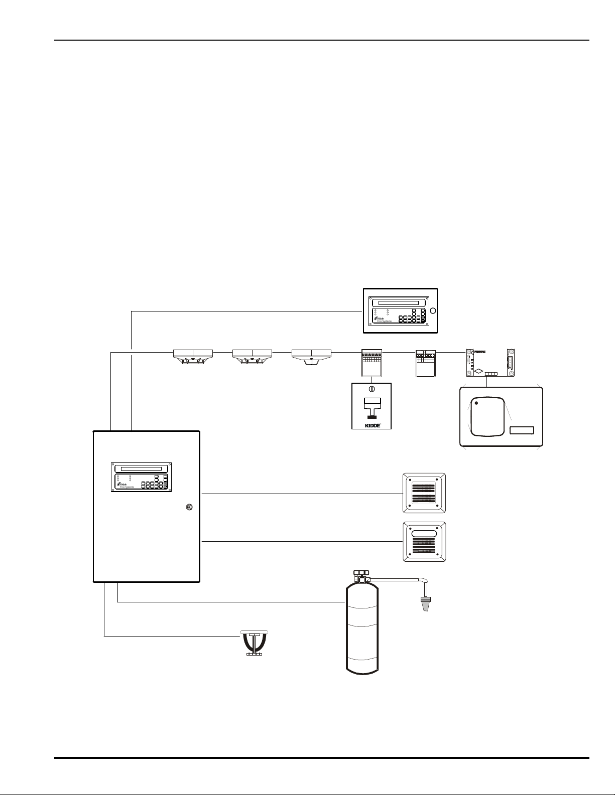
1-1 SYSTEM DESCRIPTION
The ARIES™ Fire Alarm/Suppression Control Unit is an intelligent control unit in a compact
housing for fire suppression system and/or fire-alarm system applications. The control unit uses
a single printed circuit board (PCB) design and a switching power supply. A keypad display
membrane (hereinafter referred to as the display) is mounted to the PCB for system status and
user operation.
The ARIES has one signaling line circuit (SLC) that can communicate with up to 255 intelligent
devices.
See Figure 1-1 for a typical fire suppression system application.
CHAPTER 1
Figure 1-1. Typical ARIES System
P/N 06-236530-001 1-1 August 2013
Page 24

The ARIES coordinates the operations of the varied components of a protected-premises fire
protection or notification system. These operations include:
• Interpreting initiating signals from automatic detectors or monitor modules. Initiating
signals can be any of the following:
– Automatic detector pre-alarm
– Automatic detector alarm
– Manual alarm
– Manual extinguishing-system release
– Extinguishing-system abort
– Sprinkler-system waterflow
– Sprinkler-system supervisory
– Point-specific trouble report
• Annunciating the initiating-device report, or any other system event, via the display and
associated peripheral annunciation equipment
• Notifying the occupants of an emergency situation
• Activating control equipment to aid with building evacuation or to prepare an area for
special-extinguishing-system discharge
• Discharging the special-extinguishing system, if necessary
• Actuating ancillary equipment to call the fire department
• Warning of any trouble condition that could inhibit alarm transmission or annunciation or
whose occurrence could prevent the system from carrying out its mission.
1-1.1 Standard Features
The following standard features are incorporated in the control unit's single-printedcircuit-board design:
• One (1) signaling-line circuit (SLC) for Class-A, Style -6 or -7 or Class-B, Style-4
operation
• 255 intelligent-device capacity
• Two (2) notification-appliance circuits (NACs) for Class-A, Style-Z or Class-B,
Style-Y operation. Each NAC is capable of creating the following master-coded
patterns for audible notification appliances: 60 beats per minute (bpm), 120 bpm,
temporal pattern per ANSI S3.41, and steady activation.
• Two (2) releasing circuits for actuators or solenoid-operated control heads and
valves
• Two (2) field-configurable outputs for notification appliances or solenoid-operated
control heads and valves. Each output operates in Class-A, Style-Z or Class-B,
Style-Y manner when configured as a NAC, and is capable of creating the following
master-coded patterns for audible notification appliances: 60 beats per minute
(bpm), 120 bpm, temporal pattern per ANSI S3.41, and steady activation.
• One (1) unpowered, Form-C relay contact for trouble conditions
• Three (3) programmable, unpowered, Form-C relay contacts
• One (1) RS-485 communications circuit for remote-display units or
annunciator-driver modules
• One (1) USB-style communications port for device capability
• Two (2) RS-232 serial-style communications ports.
• One (1) network-interface-card connector for integration of up to 32 control units
in full peer-to-peer operation
• One (1) operator interface with 80-character liquid-crystal display, statusindicating LEDs and control/numeric keys
August 2013 1-2 P/N 06-236530-001
Page 25
A switching power supply is located behind the printed-circuit board and supplies 5.4 A
AC POWER
ALARM
PRE-ALARM
SYSTEM TROUBLE
SUPERVISORY
SILENCE
SYSTEM
ACKNOWLED GE
SYSTEM
RESET
SILENCE
SCROLL
12 345
67 890
80 Character
Liquid Crystal Display
with LED Back Lighting
(2 Lines X 40 Characters)
12-key numeric / BACKSPACE /
ENTER keypad
ENTER Key
BACKSPACE Key
Operator Control Keys
System Status LEDs
@ 24 Vdc to support the basic control unit and its associated peripheral devices and to
charge the standby battery. The switching power supply is user-configurable to operate
from either 120 or 240 Vac, 50/60 Hz primary power.
1-2 CONTROL UNIT COMPONENTS
The ARIES System includes:
•Display
• Printed Circuit Board (PCB)
•Cabinet
• Power Supply/Battery Charger Assembly
Optional devices includes:
• Remote Display/Control Module (RDCM)
• ATM Series Driver Module (ATM-L/-R)
• Intelligent Interface Module (IIM)
• Network Interface Card (NIC)
• Fiber-Optic Converter Card (OCC)
•Trim Ring
1-2.1 Display
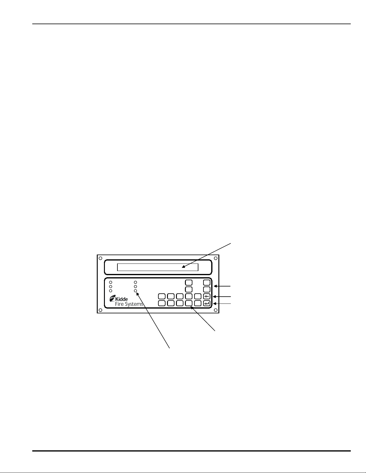
The display (Figure 1-2) has control switches, system status LEDs, an 80 character (2 x
40) LCD for event annunciation and an integral numeric keypad. The keypad is used for
entering the security password and navigating through the user menus.
Figure 1-2. ARIES Display
The following paragraphs describe the different parts of the display.
1-2.1.1 LCD AND LEDS
A window for the 80-character (two lines by 40 characters each) LCD and six
system-status LEDs. The six system-status LEDs are:
• Power On (green)
•Alarm (red)
• Pre-Alarm (yellow)
P/N 06-236530-001 1-3 August 2013
Page 26

•Trouble (yellow)
•Supervisory (yellow)
• Silence (yellow)
1-2.1.2 OPERATOR CONTROL KEYS
The operator control keys are:
• Acknowledge
•Silence
• Reset
•Scroll
1-2.1.3 DIGIT AND FUNCTIONALITY KEYS
The 12-position keypad has the following digit and functionality keys:
•Digits, 0-9
•Backspace
•Enter
Refer to Chapter 3 for system operations using the display.
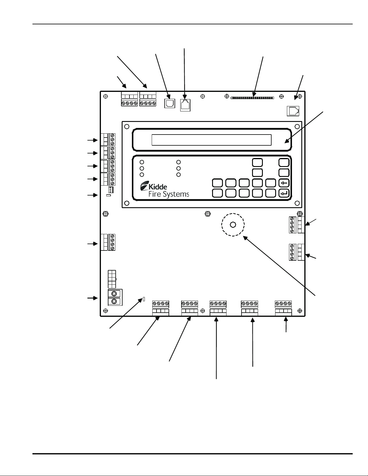
1-2.2 Printed-Circuit Board (PCB)
The ARIES’s Printed Circuit Board (PCB) contains the system’s central processing unit
(CPU) and all of the primary circuits. The PCB is packaged separately and shipped inside
the control-unit's enclosure. Figure 1-3 shows the layout of the PCB, including terminals
for external components, the operator interface, and connectors.
August 2013 1-4 P/N 06-236530-001
Page 27
Combo 2
TB6TB7
Combo 1
TB2
Aux24VDC
TB11
Release 2
TB12
Release 1
Batt Out
TB3
TroubleRelay 3Relay 1 Relay 2
1234 1234
1234
1234 1234
120
240
TB13
AC IN
NL
PSU
J12
+
+
--
CNCNO
CNCNO
CNCNOCNCNO
1234
TB5
NAC 1
TB14
1234
NAC 2
RS-232 A
J8
J5
TB15
USB B
RS 485SLC
TB1
4321 4321
Style 4
S2
J10
SLC Terminals
(TB1)
RS-485 Terminals
(TB15)
USB Port
(J6)
Network Interface
Card Connector (J5)
RS-232 Serial
Port A (J8)
Notification
Appliance
Circuit No. 2
(TB14)
Notification
Appliance
Circuit No. 1
(TB5)
Programmable Release /
Notification-Appliance
Circuit No. 2
(TB6)
Programmable Release /
Notification-Appliance
Circuit No. 1
(TB7)
24 VDC Auxiliary-Power
Terminals (TB2)
Release Circuit No. 2
(TB11)
Release Circuit No. 1
(TB12)
Prog. Relay No. 1
Prog. Relay No. 2
Prog. Relay No. 3
Trouble Relay
Battery Terminals
(TB3)
Display /
Operator
Interface
Buzzer
AC Input Terminals
(TB13)
SLC-Style Switch
(S2)
J3
RS-232 B
TB4 TB8 TB9 TB10
RS-232 Serial Port B (J3)
AC Supply Select Switch
(S4)
+
++
+
++
++ ++
+
+
+
+
--- -
-- --
-
--
-
--
Note: Polarities shown reflect the condition when the circuit is either active or in the alarm state.
AC POWER
ALARM
PRE-ALARM
SYSTEM TROUBLE
SUPERVISORY
SILENCE
SYSTEM
ACKNOWLEDGE
SYSTEM
RESET
SILENCE
SCROLL
12345
67890
P/N 06-236530-001 1-5 August 2013
Figure 1-3. ARIES Control Unit Printed Circuit Board
Page 28
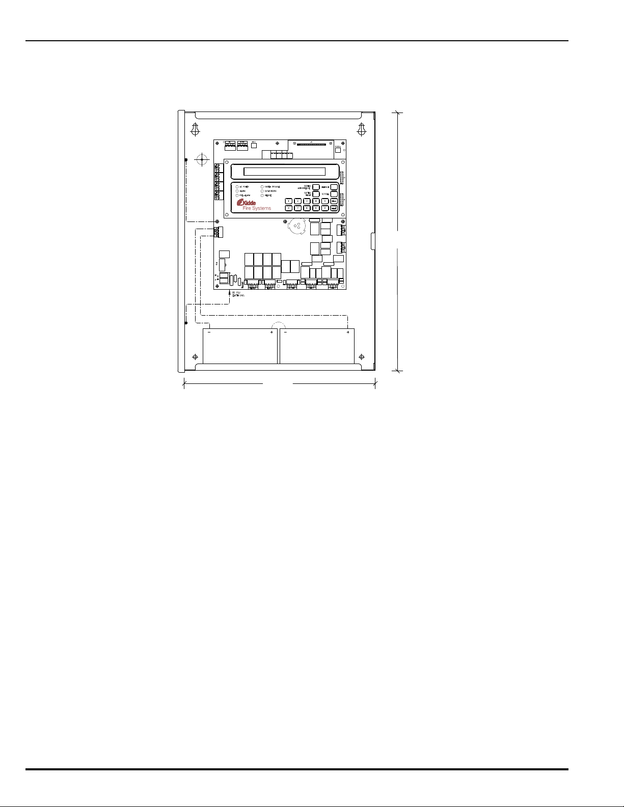
1-2.3 ARIES Cabinet
12-V Battery (12 AH)
12-V Battery (12 AH)
14-1/4 in.
19-1/2 in.
The PCB mounts in a compact (19.50” x 14.25” x 5.00”) cabinet. The cabinet is key
locked, and provides space for two batteries (up to 12 AH).
Figure 1-4. ARIES Cabinet
1-2.4 Power-Supply/Battery-Charger Assembly
The power-supply/battery-charger assembly is an AC to DC switching power-supply unit
that provides a total output of 5.4 A @ 27 Vdc. The power supply unit is user configurable
for either 120 Vac or 220/240 Vac, 50/60 Hz line voltage and its DC output is both filtered
and regulated. The power supply/battery-charger assembly can charge standby batteries
of up to 70 AH capacity.
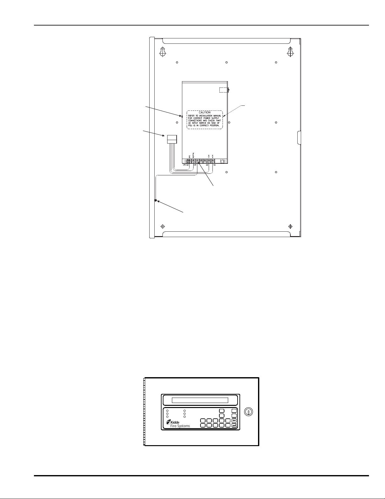
The power-supply/battery-charger assembly is packaged separately and shipped inside
the control unit’s enclosure. Figure 1-5 shows the placement of the powersupply/battery-charger assembly in the ARIES’s back box.
August 2013 1-6 P/N 06-236530-001
Page 29
1-3 OPTIONAL DEVICES
Power Supply Earth-Ground Terminal
Earth-Ground Terminal for Ground
(i.e., Green) Wire of AC-Power Supply
PSU Warning Label
AC Selector
Switch
To Printed-Circuit
Board PSU
Connector J12
AC POWER
ALARM
PRE-ALARM
SYSTEM TROUBLE
SUPERVISORY
SILENCE
SYSTEM
ACKNOWLEDGE
SYSTEM
RESET
SILENCE
SCROLL
12345
67890
Figure 1-5. Power-Supply Assembly
1-2.4.1 BATTERIES
The cabinet provides space for two 12-AH batteries. Use a separate battery
enclosure, P/N 76-100010-001, for 17-AH or larger batteries. Batteries must be
ordered separately.
Several optional devices and modules can be used with the ARIES.
1-3.1 Remote Display/Control Module (RDCM)
The remote display control module permits system events to be displayed, and operator
intervention to be accomplished, from more than one location in a facility. Remote
display control module, Model RDCM, is a duplicate of the ARIES’s Display/Control Module
and allows full operator intervention and system control.
Figure 1-6. Remote Display/Control Module
P/N 06-236530-001 1-7 August 2013
Page 30
1-3.2 ATM Series Driver Modules
16
15
14
13
12
11
10
9
8
7
6
5
4
3
2
1
Lamp Test
Com
Ack
Reset
Silence
Drill
32
31
30
29
28
27
26
25
24
23
22
21
20
19
18
17
LK19
LK21
LK18
LK20
LK23
LK22
LK25 LK24
LK27 LK26
LK29 LK28
LK31 LK30
LK32
LK17
LK15LK16
LK13LK14
LK11LK12
LK10
LK8
LK6
LK4
LK2
LK9
LK7
LK5
LK3
LK1
Trouble
Sup.
Sil. Out
Pre Alm
Alarm
Pwr On
A
B
+24 V
Com
PS Flt
W1
Out B
Out A
In B
In A
S2 S1
ATM-L/R
Earth Gnd
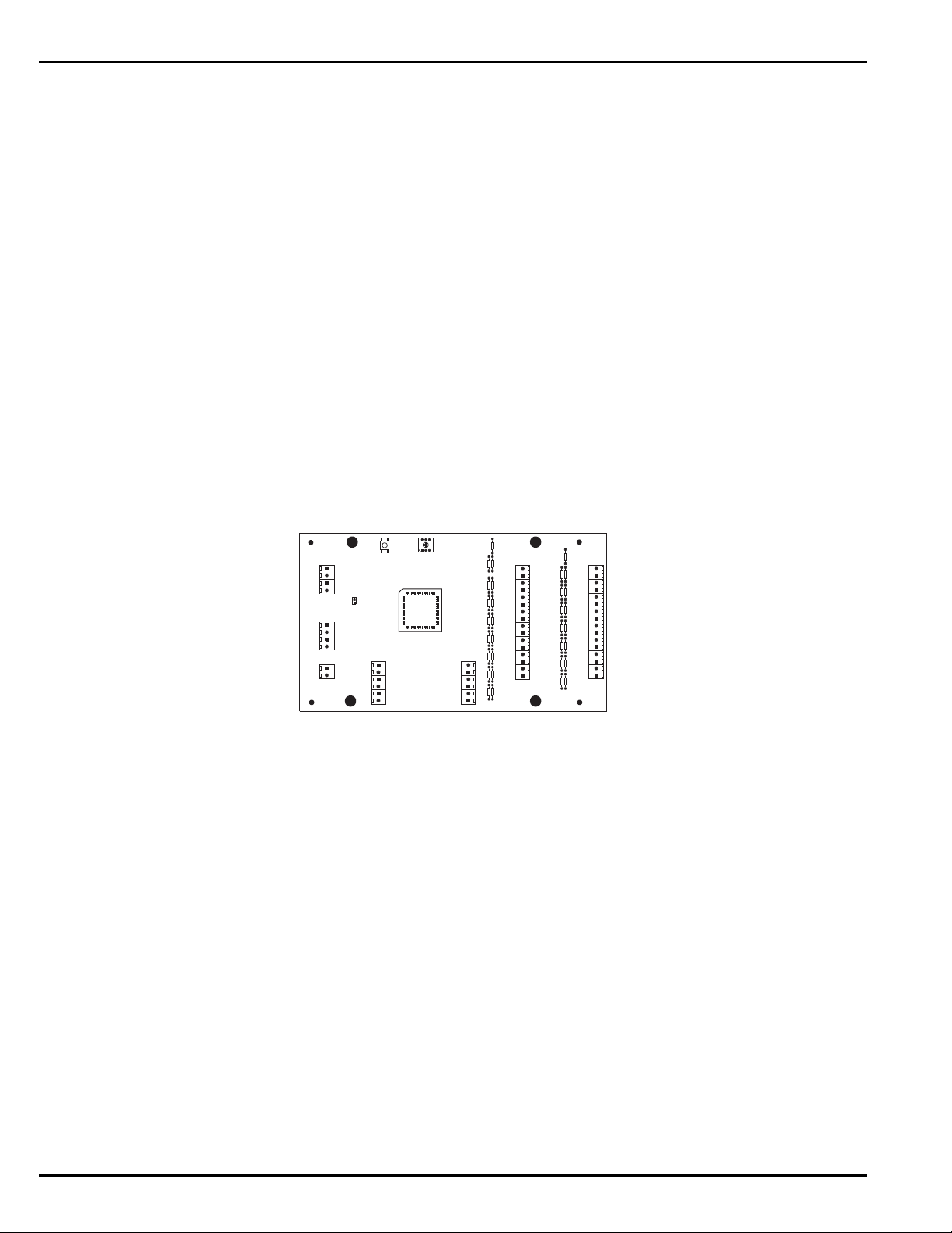
The ATM Series Driver Modules permit third-party graphical annunciators and large
numbers of auxiliary relays to be used with the ARIES. Two types of driver modules can
be used, Models ATM-L and ATM-R.
The ARIES supports up to 16 ATM-L or ATM-R Driver Modules, or any combination of
these two modules, together with RDCMs, that does not exceed 31 total addresses.
1-3.2.1 MODEL ATM-L ANNUNCIATOR DRIVER MODULE
The Model ATM-L Annunciator Driver Module provides the ARIES with up to 32
programmable, supervised LED outputs for graphical or tabular annunciators,
along with 6 system-level LED outputs and 5 system-level input circuits for
functional switches.
The system-level LEDs correspond to the following general conditions: Module
Power, Pre-Alarm, Alarm, Alarm Silence, Supervisory, and Trouble.
The input circuits for functional switches provide for the following operator
intervention: System Reset, Event Acknowledgement, Alarm Silence, Fire Drill,
and Lamp Test.
1-3.2.2 MODEL ATM-R RELAY DRIVER MODULE
The Model ATM-R Relay Driver Module (Figure 1-7) can activate up to 32
programmable, supervised relays.
Figure 1-7. Model ATM-R Relay Driver Module
1-3.3 Network Interface Card (NIC)
The Network Interface Card (NIC), shown in Figure 1-8, allows up to 32 ARIES Control
Units to be combined into an integrated, peer-to-peer network for annunciation, event
output control, and operator intervention. The NIC regenerates and boosts network
communications between ARIES Control Units and electrically isolates the networked
control units from each other.
August 2013 1-8 P/N 06-236530-001
Page 31
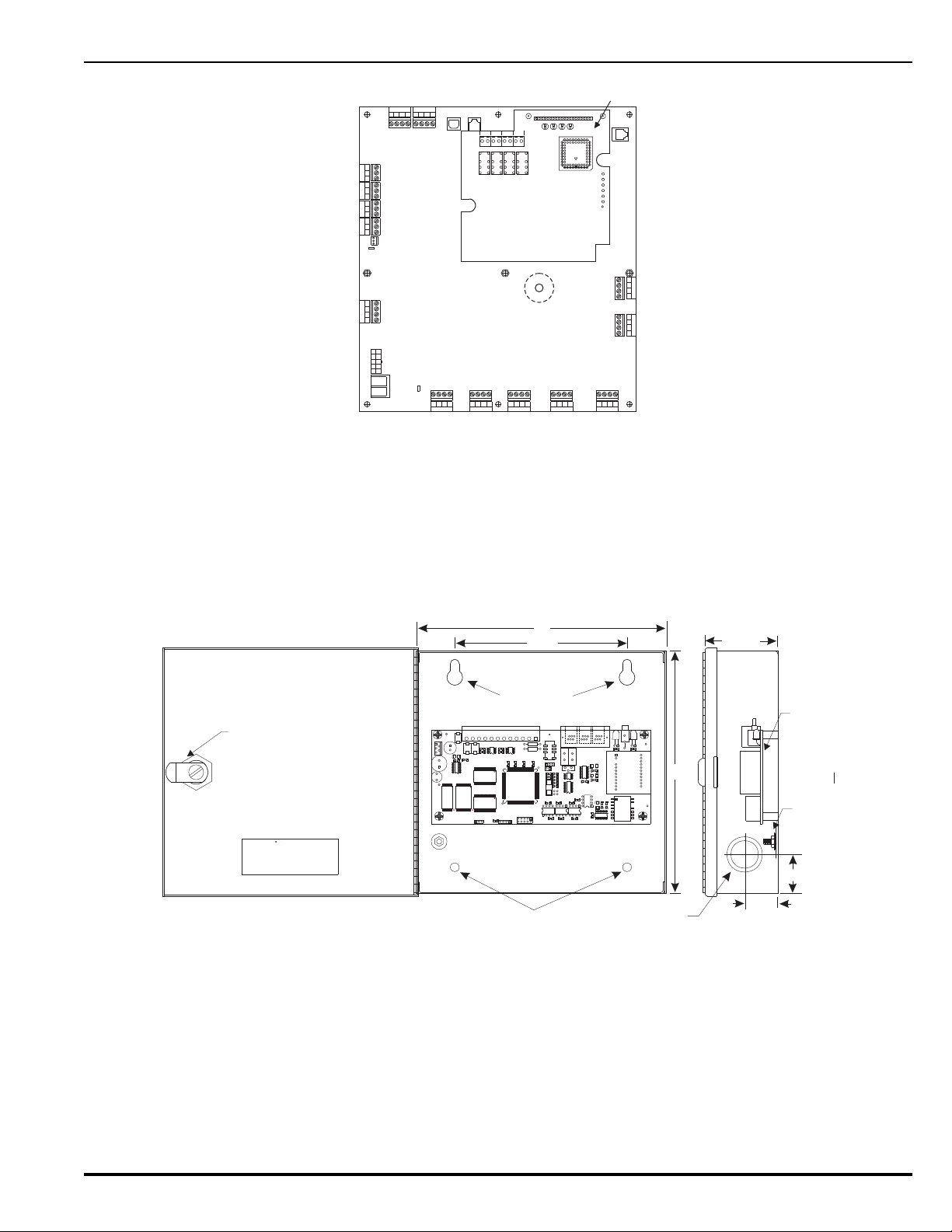
Figure 1-8. Network Interface Card (shown mounted to PCB)
Combo 2
TB6TB7
Combo 1
TB2
Aux 24 VDC
TB11
Release 2
TB12
Release 1
Batt Out
TB3
TroubleRelay 3
Relay 1
Relay 2
1234 1234
1234
12 34 12 34
120
240
TB13
ACI N
NL
PSU
J12
+
+
--
CNCNO
CNCNO
CNCNOCNCNO
1234
TB5
NAC1
TB14
1234
NAC2
RS-232 A
J8
J3
TB15
USB B
RS 485SLC
TB1
4321 4321
Style 4
S2
J10
Network Interface Card
B2NA2B1NA1 B2IA2 B1IA1
TB1TB3TB2TB4
K1K3K2K4
J1
DS4 DS2 DS3 DS1
N2 N1 I2 I1
U11
GND
TP1
+5
TP2
I1
TP3
N1
TP4
N2
TP5
I2
TP6
RS-232 B
J6
CAT.NO. 89-100083-001
MODEL: IIM-2000
KIDDE-FENWAL,INC.
400MAIN STREET,ASHLAND, MA 01721
TEL:(508) 881-2000 FAX:(508) 881-8920
R
ASHLAND, MA. 01721
KIDDE-FENWAL, INC.
IIM-2000
ASSY N0. 06-129728-001
PC CCM
TEL
-1
Module
Side View
Front View with Door Open
Latch
Ground
Lug
8"
5-1/2"
8"
2-9/32"
9/32" Diameter
9/32" Diameter
½" & ¾"
Knockout (2)
1-1/4"
1-1/16"
1-3.4 Intelligent Interface Module (IIM)
The Intelligent Interface Module (IIM), shown in Figure 1-9, provides a communications
link to a network up to 127 ORION-XT Detectors for centralized data exchange, alarm
reporting, detector configuration, and history-log downloading.
Refer to the ORION-XT Installation, Operation and Maintenance Manual (Part Number
77.100) for a complete description of the Intelligent Interface Module.
1-3.5 Fiber Optic Converter Card
The Fiber Optic Converter Card (OCC), shown in Figure 1-10, converts electrical signals
from the Network Interface Card into light pulses for data transmission over 62.5/125
Figure 1-9. Intelligent Interface Module
m duplex fiber optic media. The OCC permits distances of up to 1 mile (5,280 ft.)
between networked ARIESs.
P/N 06-236530-001 1-9 August 2013
Page 32
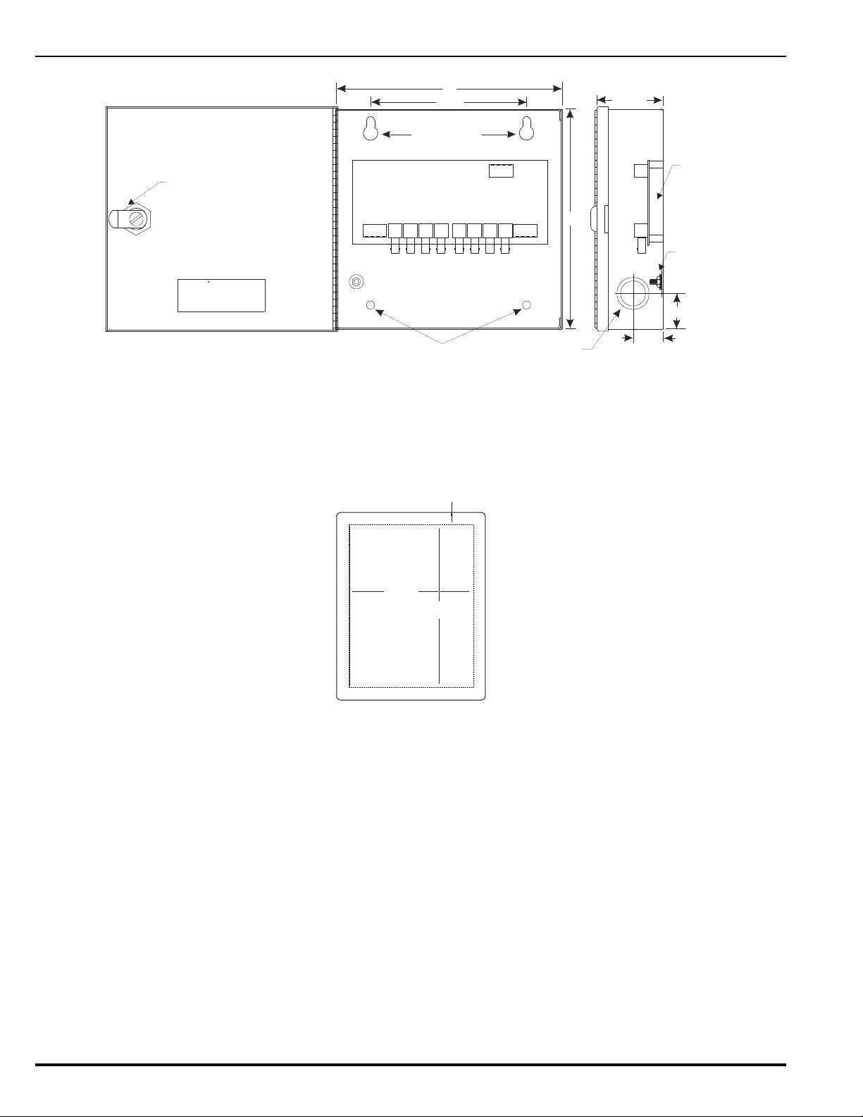
Figure 1-10. Fiber Optic Converter Card
MODEL: OCC
KIDDE-FENWAL,INC.
400MAIN STREET,ASHLAND, MA 01721
TEL:(508) 881-2000 FAX:(508) 881-8920
R
Module
Side View
Front View with Door Open
Latch
Ground
Lug
8"
5-1/2"
8"
2-9/32"
9/32" Diameter
9/32" Diameter
½" & ¾"
Knockout (2)
1-1/4"
1-1/16"
B2N B2I
TB1 TB2
RxN
A2N A2I
B1N B1IA1N A1I
TxN RxI
Q1 D1 Q2 D3
TxI RxN TxN RxI TxI
Q3 D5 Q4 D7
24V
+-+-
19-5/16 in.
14-9/16 in.
1-1/2 in.
All Around
1-3.6 Trim Ring
A trim ring (Figure 1-11) is available to semi-flush mount the control unit.
1-4 SMARTONE DETECTORS
The ARIES uses the SmartOne™ Series of intelligent smoke and heat detectors. These detectors
have their own data transceivers, micro-controllers, micro-controller memory, and algorithms
that allow the detectors to determine whether a normal, pre-alarm, alarm, or trouble condition
exists at their monitoring locations. Each detector continuously transmits its current status to
the ARIES through the signaling line circuit, and responds to control unit polling and inquiries by
the address that is set in the detector using the Handheld Programmer, P/N 74-200013-001, or
using the ARIES’s display. The pre-alarm and alarm thresholds are programmable for each
detector.
A blinking LED on an intelligent detector indicates communications between the detector and
the control unit.
Figure 1-11. Trim Ring
August 2013 1-10 P/N 06-236530-001
Page 33
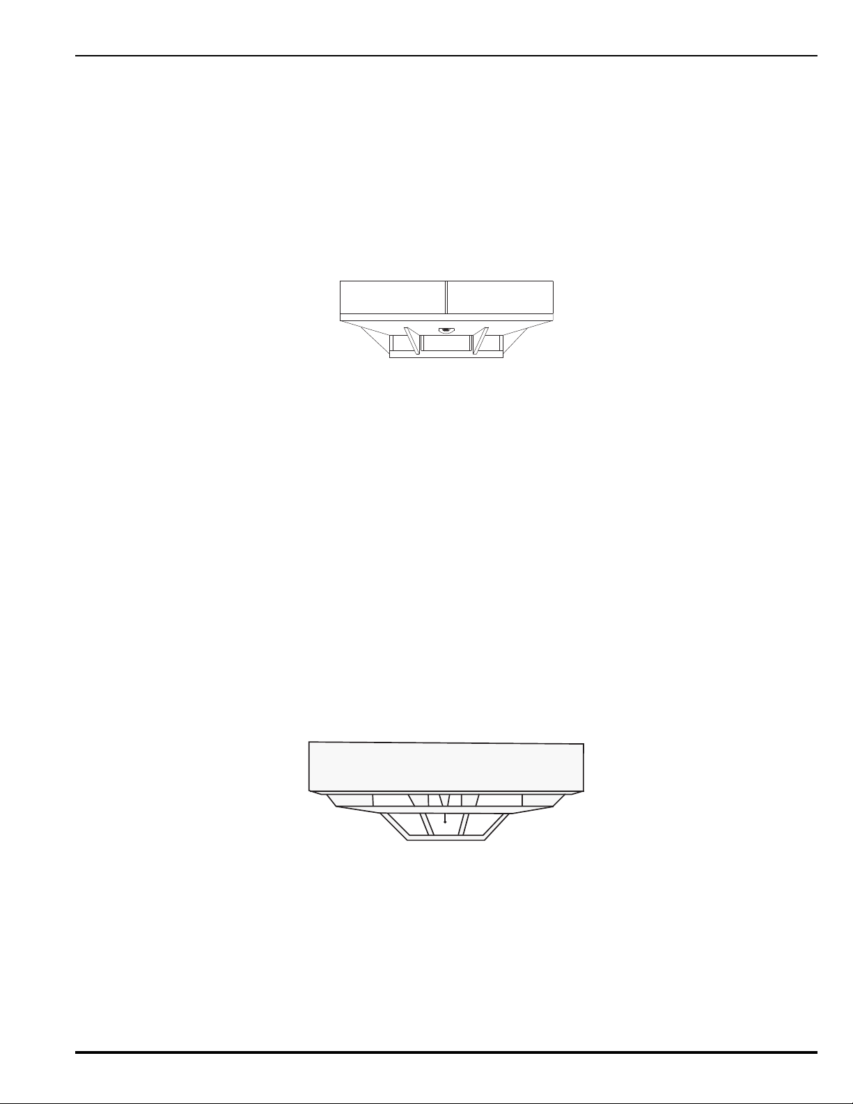
1-4.1 SmartOne Ionization Smoke Detector, Model CPD-7052
The Model CPD-7052 Ionization Smoke Detector is a low-profile, intelligent smoke
detector that uses an ionization sensing chamber. This detector can be utilized for openarea coverage or can be mounted in a duct with air velocities up to 2,000 feet per minute.
Ionization detectors respond best to small smoke particles characteristic of flaming fires,
and are used primarily in areas where such fires are anticipated. They are also used in
special extinguishing systems as one criterion to release the extinguishing agent. See
Figure 1-12.
Note: Older-style Model CPD-7040 Ionization Detectors may be used with the ARIES
Control Unit.
Figure 1-12. SmartOne™ Smoke Detector
1-4.2 SmartOne Photoelectric Smoke Detector, Model PSD-7152
The Model PSD-7152 Photoelectric Smoke Detector is a low-profile, intelligent smoke
detector that uses a light-scattering sensing chamber. This detector can be utilized for
open-area coverage or can be mounted in a duct with air velocities up to 4,000 feet per
minute.
Photoelectric detectors respond best to large smoke particles characteristic of smoldering
fires, and are used primarily in areas where such fires are anticipated and in high-velocity
underfloor applications. They are also used in special extinguishing systems as one
criterion to release the extinguishing agent. See Figure 1-12.
Note: Older-style Model PSD-7140 Photoelectric Detectors may be used with the ARIES
Control Unit.
1-4.3 SmartOne Thermal Detector, Model THD-7252
The Model THD-7252 Thermal Detector is a low-profile, intelligent heat detector that uses
a thermistor sensing chamber for fast response. This detector can be used for open-area
coverage on low (< 10 ft.), flat ceilings with a spacing up to 70 ft. Smaller coverage is
required for high ceilings and ceilings with structural obstructions.
Figure 1-13. THD-7252 Thermal Detector
P/N 06-236530-001 1-11 August 2013
Page 34
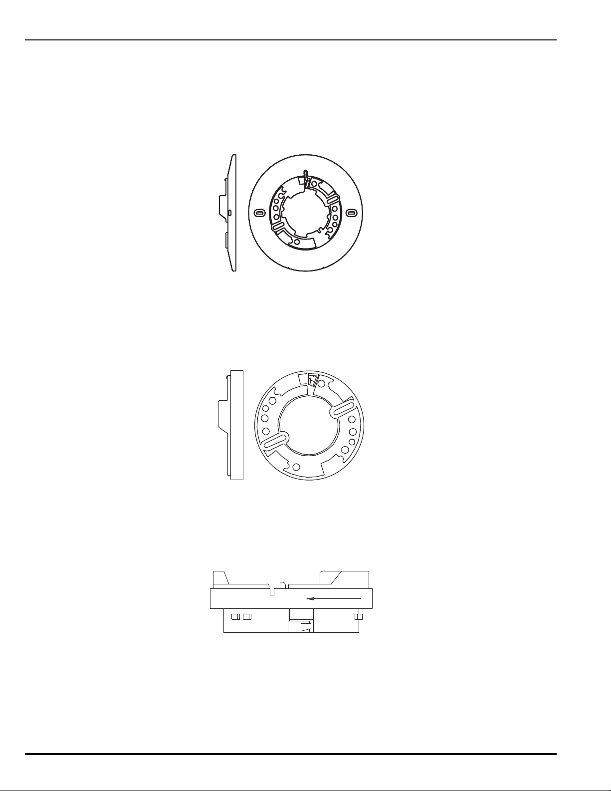
1-4.4 Detector Bases
Two detector bases are available.
1-4.4.1 FLANGED DETECTOR BASE, MODEL 6SB
The Model 6SB Detector Base is used in applications where the detector's installed
appearance is a primary consideration. This base mounts to standard 3-, 3½-,
and 4-inch electrical boxes.
Figure 1-14. 6SB Detector Base (Flanged)
1-4.4.2 FLANGELESS DETECTOR BASE, MODEL 4SB
The Model 4SB Detector Base is used in underfloor applications, or in applications
where the detector’s installed appearance is not a primary consideration. This
base mounts to standard 3- or 3½-inch electrical boxes.
Figure 1-15. 4SB Detector Base (Flangeless)
1-4.5 Detector Base Adapter, Model MA-002
The Model MA-002 Detector Base Adapter allows the low-profile SmartOne detectors to
be retrofitted into the older-style SmartOne detector base, P/N 70-400000-001.
Figure 1-16. MA-002 Detector Base Adapter
August 2013 1-12 P/N 06-236530-001
Page 35
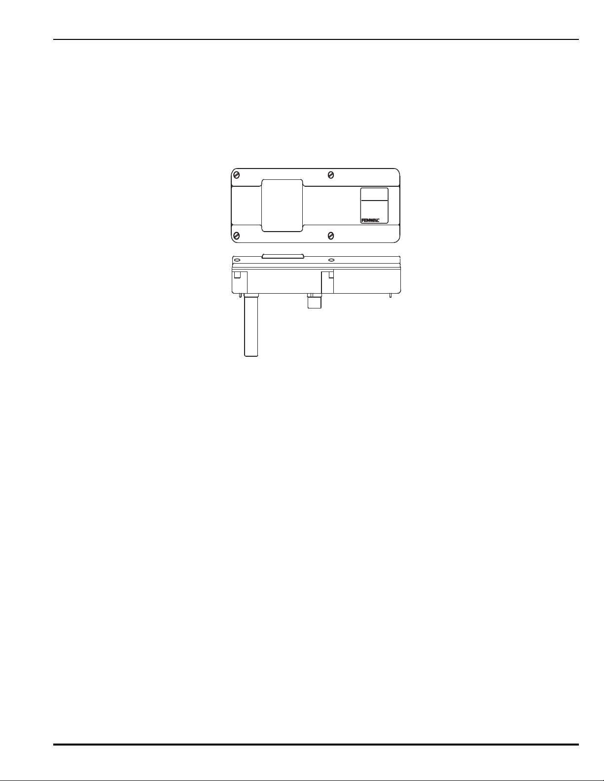
1-4.6 Duct Housing, Model DH-2000
DUCT
DETECTOR
MODEL
DH-2000
R
The Model DH-2000 Duct Housing is used to enclose an intelligent smoke detector that
is mon i t o r ing for s m o ke in a n a i r duct a n d is located outside of the duct. The duct housing
is used with inlet and outlet tubes that allow the air in the duct to be sampled uniformly
and transported to the enclosed smoke detector for obscuration-level measurement.
Note: Older-style DH-4000 Duct Housings with Model CPD-7040 Ionization Detectors or
Model PSD-7140 Photoelectric Detectors may be used with the ARIES Control
Unit.
Figure 1-17. DH-2000 Duct-Detector Housing
1-5 SMARTONE ADDRESSABLE MODULES
SmartOne addressable modules are of three general types:
• Monitor Modules. These modules provide a uniquely-identifiable interface between the
ARIES and an initiating device.
• Relay Module. This module supplies an unpowered, Form-C contact at a point-specific
address.
• Control Modules. These modules provide a uniquely-identifiable interface between the
ARIES and conventional notification appliances such as horns and strobes.
Each addressable module continuously transmits its current status to the ARIES Control Unit via
the signaling line circuit, and responds to control unit polling, inquiries, and activation
commands by the address that is set in the module using the Handheld Programmer,
P/N 74-200013-001, or using the ARIES’s display.
1-5.1 Addressable Monitor Module, Model AI
Two styles of Model AI Addressable Monitor Modules are available: The Model AI (NO)
P/N 70-4070X8-001 is used to monitor conventional, unpowered, normally-open contacttype devices such as manual stations, waterflow switches and supervisory switches
through a Class B initiating device circuit. The Model AI (N.C.), P/N 70-407008-002, is
intended for use within control equipment providing the normally closed trouble contact
and is not considered an initiating device circuit.
The AI Modules are designed to be mounted in the electrical box of the device being
monitored.
P/N 06-236530-001 1-13 August 2013
Page 36
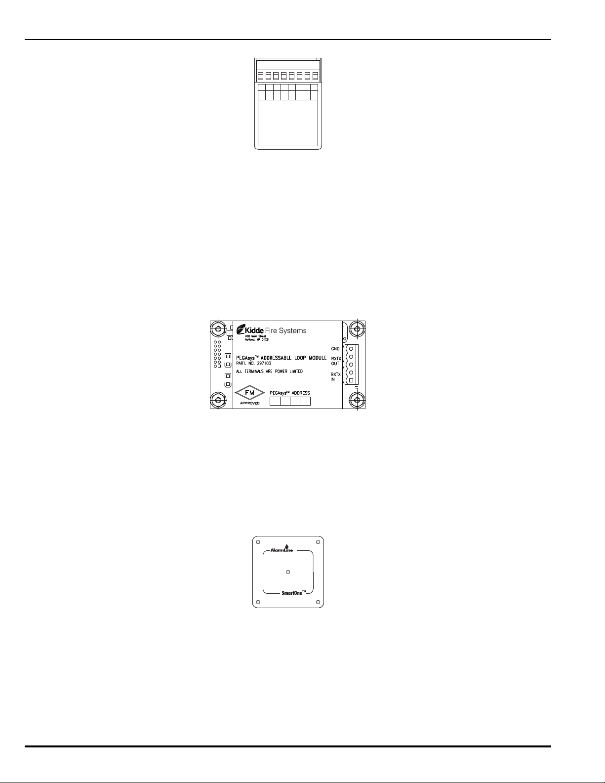
Figure 1-18. AI Monitor Module
MODEL AI, N/O
INSTRUCTIONS
SEE INSTALLATION
CAT.NO. 70-407008-001
SmartOne
TM
FOR SERVICE SEND TO:
KIDDE-FENWAL, INC.
400 MAIN ST.
ASHLAND, MA 01721
DATEOF MANUFACTURE:
MAX. INSTALL.TEMP. 120°F
7654321
06-235578-001
PC PC PC PC
(+) (-) (+) (-)
8
ASWB
SW
(+)
LED
(-)
LED
ALLTERMINALS ARE POWER LIMITED
TM
Note: Older-style Monitor Modules, P/N 70-40700X-00X, may be used with the ARIES
Control Unit.
1-5.2 ORION-XT Interface Module, Model PALM
The Model PALM ORION-XT Interface Module is a monitor module that enables a High
Sensitivity Smoke Detector (HSSD) to report pre-alarm, alarm, and trouble signals to the
ARIES Control Unit via its signaling line circuit. The AIM mounts inside the ORION-XT
detector housing.
Note: The PALM address cannot be set via the Handheld Programmer. Use either the
OCS Software or the ARIES’ display to set the PALM’s address.
Figure 1-19. ORION-XT Interface Module
1-5.3 Addressable AlarmLine Module, Model AAM
The Model AAM Addressable AlarmLine Module is a monitor module that enables an
AlarmLine sensor cable to report pre-alarm and alarm or overheat events, and trouble
signals to the ARIES through the signaling line circuit. The AAM, P/N 73-100001-001, is
equipped with a metal cover plate for mounting to a 4” square electrical box.
P/N 73-100003-001, is a surface-mount, NEMA-4 enclosure for the AAM.
Figure 1-20. Addressable AlarmLine Module
August 2013 1-14 P/N 06-236530-001
Page 37
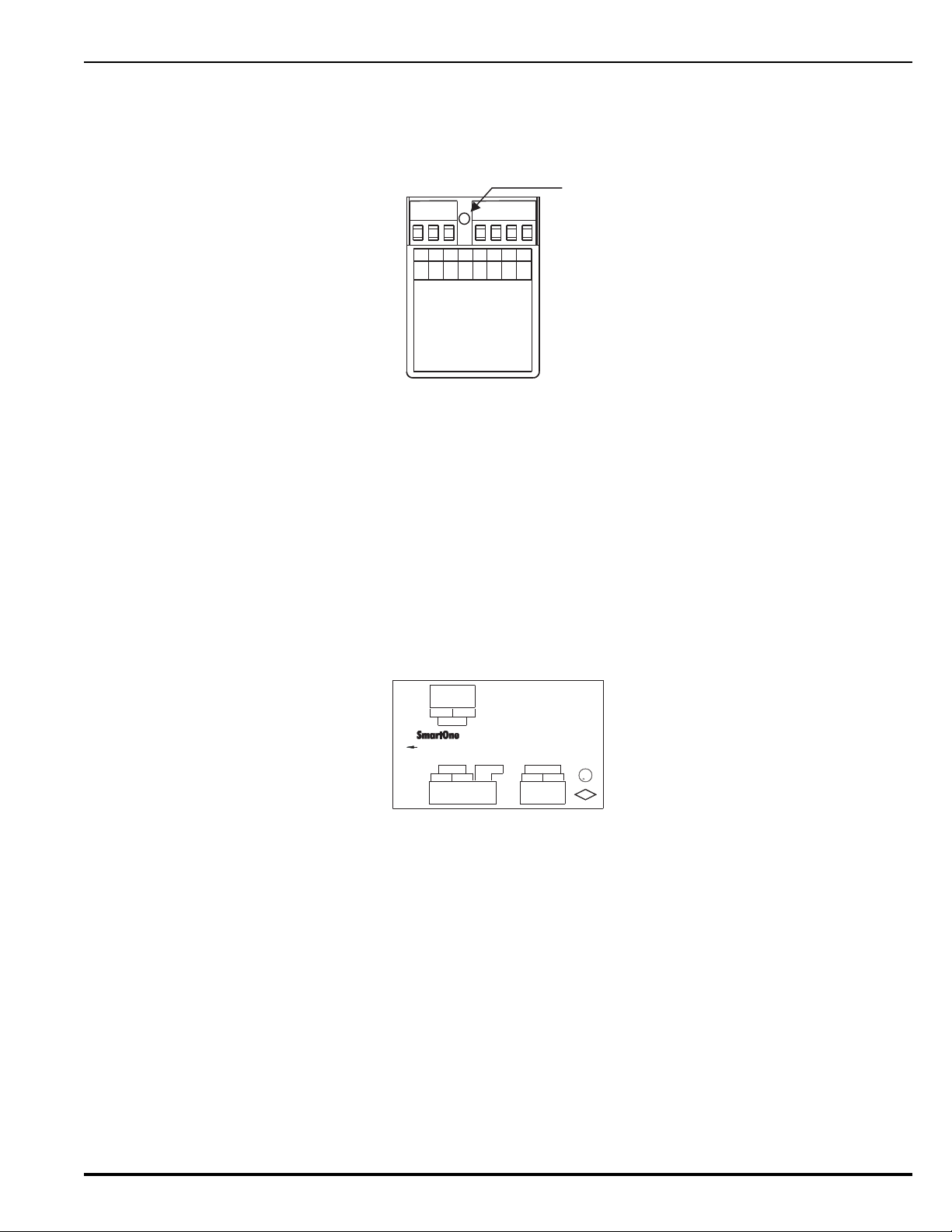
1-5.4 Addressable Relay Module, Model AO
MODEL AO
INSTRUCTIONS
SEE INSTALLATION
CAT. NO. 70-408004-001
SmartOne
TM
FOR SERVICE SEND TO:
KIDDE-FENWAL, INC.
400 MAIN ST.
ASHLAND, MA 01721
DATE OF MANUFACTURE:
MAX. INSTALL. TEMP. 120°F
765
4321
06-235577-001
PC PC PC PC
(+) (-) (+) (-)
N/C
COM
N/O
TERMINALS 5-7 ARE POWER LIMITED
TERMINALS 1-4 ARE POWER LIMITED
LED
A B BA
-+-+
+ - - +
KIDDE-FENWAL, INC.KIDDE-FENWAL,INC.
ASHLAND, MA 01721 U.S.A.ASHLAND,
MA 01721 U.S.A.
CAT.NO. 70-200200-001CAT.
NO. 70-200200-001
INSTRUCTIONS P/N 06-235717-001INSTRUCTIONS
P/N 06-235717-001
ALL OTHERS - POWER LIMITEDALL OTHERS
- POWER LIMITED
DEVICE
ADDRESS #ADDRESS
# _____ _ _ _
AUX./AUDIO MODEAUX./AUDIO
MODE
SETTINGSSETTINGS
PC LINE TERMINALS - POWER LIMITEDPC LINE TERMINALS - POWER LIMITED
ADDRESSABLE SIGNAL/SOUNDER MODULE (ASM)ADDRESSABLE SIGNAL/SOUNDER MODULE (ASM)
_____ _ _ _
INSTRUCTIONS P/N 06-235717-001INSTRUCTIONS
P/N 06-235717-001
ADDRESS #ADDRESS #
SETTINGSSETTINGS
AUDIO
P1=1&2
MODEMODE
S1=3 ONS1=3
ON
AUX. INAUX. IN
+ - + -
TROUBLE
CKT.
-
OUTPUT CKT.
-+ +
AUX./AUDIO MODEAUX./AUDIO MODE
AUXILIARY
MODEMODE
P1=2&3
S1=1&2 ONS1=1&2
ON
PC LINEPC LINE
A B A B
DEVICE
ALL OTHERS - POWER LIMITEDALL OTHERS
- POWER LIMITED
CAT.NO. 70-200200-001CAT.
NO. 70-200200-001
ASHLAND, MA 01721 U.S.A.ASHLAND,
MA 01721 U.S.A.
KIDDE-FENWAL, INC.KIDDE-FENWAL,
INC.
FM
APPROVED
R
L
U
TM
The Model AO Addressable Relay Module provides an unpowered, Form-C contact for
remote control applications. The AO Module is designed to be mounted in the electrical
box of the device being controlled.
Figure 1-21. AO Relay Module
Note: Older-style Relay Modules, P/N 70-40800X-000, may be used with the ARIES
Control Unit.
1-5.5 Addressable Signal Module, Model ASM
The Addressable Signal Module permits notification appliances to be controlled by
commands issued via the ARIES’s SLC. The ASM is supplied with a thermoplastic
mounting cover and is designed to mount in a standard 4-11/16” electrical box or a 4”
square, extra-deep electrical box.
Note: Set the ASM to the audio mode and install the end-of-line resistors across the
trouble-monitoring and output circuits before you address the ASM with the
Handheld Programmer or the ARIES’s display. Return the module to the Auxiliary
Mode before you use the ASM with the ARIES.
1-5.6 Remote Releasing Module
P/N 06-236530-001 1-15 August 2013
Figure 1-22. ASM Addressable Signal Module
The Remote Releasing Module (RRM) provides the ability to remotely activate
extinguishing-system control devices (for example, electro-explosive actuators and
solenoid valves). Connection is via the SmartOne-compatible Control Panel’s Signalling
Line Circuit (SLC). The module is field-programmable using the Control Panel keypad or
Hand-Held Programmer.
A maximum of 64 RRMs can be activated consecutively via the ARIES Control Panel. Up
to 16 RRMs can be configured in a group for simultaneous activation. The ARIES SLC can
support up to 4 groups.
The RRM is intended for indoor dry location use, and is available in two models, one for
mounting in a standard electrical box and a second model for mounting in suitable UL864 Listed cabinets.
Page 38
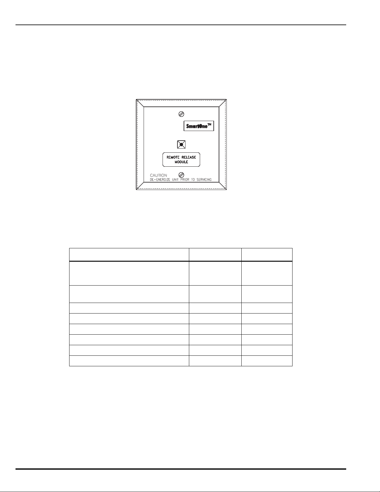
P/N 70-600000-001: Standard Mounting
• North American 4-11/16 in. electrical box with a double gang plaster ring
(Rayco Model 841 or equivalent), 1/2 in. raised
• 4 in. square, 2-1/8 in. deep electrical box
P/N 70-600000-002: In-Cabinet Mounting
• Any suitable UL-864 Listed enclosure with no other electronics.
Figure 1-23. Remote Releasing Module
The following power supplies are compatible with the Remote Releasing Module.
Table 1-1. Compatible RRM Power Supplies
Description Manufacturer Part Number
Multi-Zone Power Supply Assembly
(used with P/N: 77-297107-000
enclosure and cables)
24 VDC, 1 A Auxiliary Power Ouput of
ARIES Control Unit, qty 2 (See Note)
24Vdc, 3A Power Supply, red enclosure Altronix AL400ULXR
24Vdc, 3A Power Supply, grey enclosure Altronix AL400ULX
24Vdc, 6A Power Supply, red enclosure Altronix AL600ULXR
24Vdc, 6A Power Supply, grey enclosure Altronix AL600ULX
24Vdc, 8A Power Supply, red enclosure Altronix AL1024ULXR
24Vdc, 8A Power Supply, grey enclosure Altronix AL1024ULX
Kidde 77-297106-000
Kidde 76-600000-001
Note: Both auxiliary circuits may be wired together to obtain 2 A at 24 VDC, and the maximum
load on the RRM output should not exceed 2 A.
Altronix power supplies may be ordered through an authorized Altronix dealer. For a list
of dealers, visit www.altronix.com or call (888)-258-7669.
When Installing the RRM, refer to the RRM Installaton Sheet. Also, see Paragraph 2-11 for the
release circuit wiring instructions, and Appendix E for rating guidelines for power-limited and
non power-limited wiring. For configuration instructions, refer to the ARIES Configuration
Software User’s Guide (P/N 06-236530-002).
August 2013 1-16 P/N 06-236530-001
Page 39
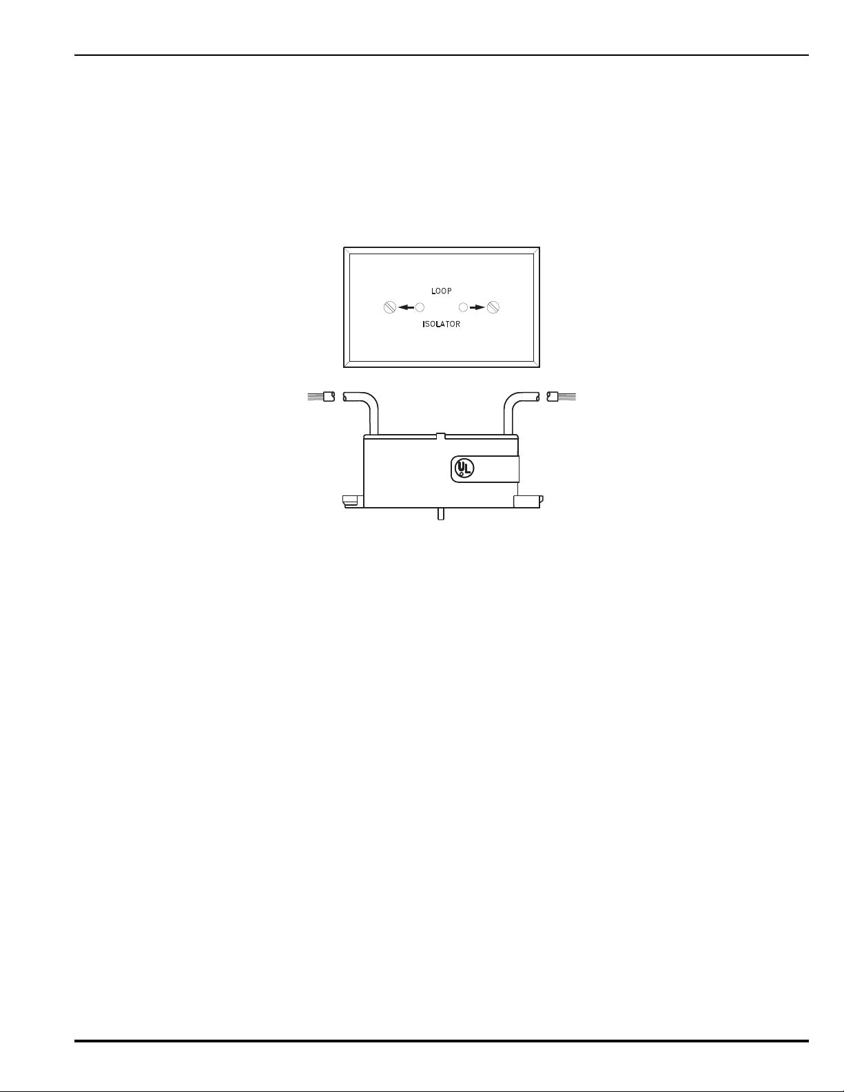
1-6 ISOLATOR MODULES
Laboratories
Underwriters
R
LISTED
Isolator modules are automatic switches that open a segment of the signaling line circuit when
a short-circuit fault is detected in that segment. The remainder of the signaling line circuit
continues to function normally and is unaffected by the short-circuit fault. The isolator modules
will close and resume normal operation when the short-circuit fault is removed.
Isolator module, P/N 74-200012-002, is supplied with a plastic cover plate for mounting to a
single-gang electrical box. Isolator module, P/N 74-200012-004, is designed to mount in the
electrical box for the Model 6SB detector base.
Figure 1-24. Isolator Modules
P/N 06-236530-001 1-17 August 2013
Page 40

1-7 SPECIFICATIONS
1-7.1 Electrical Specifications
The electrical specifications for the ARIES are as follows:
1-7.1.1 PRIMARY AC POWER
Primary AC connections are made through AC input-power terminals, TB 13, on
the ARIES main PCB. Wire size is #14 AWG minimum with 600 Vac insulation.
• 120 Vac, 50/60 Hz, 3.2 A, or
• 240 Vac, 50/60 Hz, 1.6 A
Primary power is selected by the setting of slide switch on the side of the power
supply and by the setting of Switch S4 on the printed-circuit board. Refer to
Paragraph 2-5 and Paragraph 2-7.
Note: Physically disconnect the standby battery and remove primary AC power
if the power supply is accidentally short-circuited. Resume normal
operations by restoring the AC power and physically reconnecting the
standby battery after correcting the short-circuit fault.
1-7.1.2 BATTERY AND CHARGING CIRCUIT
Only use sealed, lead-acid batteries. Maximum battery charging circuit capacity
is 70 AH. (Batteries larger than 12 AH require P/N 76-100010-001 or other UL
Listed battery cabinet.) Refer to Appendix A, Table A-3, for estimated standby
times.
• Charging Circuit Voltage: 27.0 Vdc (nominal)
• Charging Circuit Current: 6.0 A (maximum)
1-7.1.3 SIGNALING LINE CIRCUIT
Connections between the control unit, the signaling line circuit, and the associated
SmartOne peripheral devices are supervised and power-limited.
•Wiring
– Class B, Style 4
– Class A, Style 6
– Class A, Style 7 (Note: Requires Isolator Modules.)
• Voltage: 24 Vdc nominal
• Maximum Resistance: 40 ohms
• Maximum Capacitance: 0.5 F
• Maximum Current: 350 mA (short circuit)
1-7.2 Mechanical Specifications
The mechanical specifications for the ARIES are as follows:
• 14¼ in. wide x 19 in. high x 5 in. deep (enclosure only)
• 14¼ in. wide x 19-5/32 in. high x 5-1/16 in. deep
1-7.3 Environmental Specifications
The environmental specifications for the ARIES are as follows:
• Temperature: 32°F - 120°F
• Humidity: 93% at 90°F (non-condensing)
August 2013 1-18 P/N 06-236530-001
Page 41

1-7.4 Notification-Appliance and Releasing Circuits
All circuits are power-limited except where noted.
NAC Rating Regulated 24 Vdc
NAC Wiring Class A, Style Z
Class B, Style Y
Note: NACs suitable for synchronized and non-synchronized notification appliances.
Use polarized notification appliances only. The maximum number of
synchronized devices is 25.
Max. Wiring Voltage Drop: 2 V (for NACs)
Varies (for Releasing Circuits)
Refer to Paragraph 2-9 through
Paragraph 2-11
Operating Voltage: 24 Vdc (nominal)
Max. NAC Current: 1.5 A
Max. Rel. Ckt. Current: 2.4 A
Max. Current for all external devices: 5.0 A
Note: External devices include notification appliances, releasing solenoids, SLC
initiating and control devices, and all devices powered from the 24 Vdc
Auxiliary-Power Terminals (TB 2).
NAC End-of-Line Resistor: 10 K, 0.5 W
Releasing Circuits: Releasing circuits are not power-limited when
1-7.5 Relays
The three programmable relays and the trouble relay can be used for either powerlimited or non-power-limited circuits. Contact ratings for these relays are:
• 1.0 A @ 30 Vdc (resistive)
• 0.5 A @ 30 Vdc (inductive)
• 0.5 A @ 120 Vac (inductive).
1-7.6 Auxiliary Outputs
The auxiliary outputs are power limited.
• Operating Voltage Range: 18.8 - 27.6 Vdc
• Maximum Current: 1.0A (each circuit)
• Maximum Current for all external devices: 5.0A
Note: External devices include notification appliances, releasing solenoids, SLC initiating
and control devices, and all devices powered from the 24 Vdc Auxiliary
Power Terminals (TB 2). All applicable compatible devices contained in this
manual may be used.
actuators are used or when In-Line Device is
not used for solenoid valves
Use In-Line Device, P/N 06-220023-001, to
make a single-solenoid or dual-solenoid
releasing circuit power-limited
P/N 06-236530-001 1-19 August 2013
Page 42

1-7.7 Electrical Supervision
• A short circuit from any field-wiring terminal (except AC-Power-Input Terminals and
Form-C Relay Terminals) to earth ground will create a “Ground-Fault” trouble
condition.
• An open circuit in the wiring for the SLC, the outputs (NACs, release circuits, and
combination circuits), the RS-485 communications circuit, and the battery-charging
circuit will create an “Open” trouble condition.
• A short circuit between conductors in the wiring for the SLC, the outputs (NACs,
release circuits, and combination circuits), the RS-485 communications circuit, and
the battery-charging circuit will create a “Short” trouble condition.
Exception: Release circuits and combination circuits wired as non-power-limited.
• Impedance values for open-circuit and short-circuit conditions are:
– open circuit: infinite ohms
– short circuit: zero (0) ohms
August 2013 1-20 P/N 06-236530-001
Page 43

CHAPTER 2
INSTALLATION
This chapter is intended for system installers. It provides information necessary to
successfully prepare for and install the ARIES™ Fire Alarm/Suppression Control Unit. The
system design is based on the requirements of Kidde Fire Systems, Underwriters
Laboratories (UL), the Factory Mutual System (FM), and codes and standards of the
National Fire Protection Association. In all cases, the installation must meet the
requirements of the local Authority Having Jurisdiction (AHJ).
Refer also to the Installer’s Wiring Diagram, P/N 06-236406-002, that is packaged with the
control unit.
2-1 PREPARING FOR INSTALLATION
Complete the following preparation procedures before installing the control unit.
2-1.1 Control-Unit Components
Check the contents of the ARIES shipping carton to ensure that you have received the
following components:
• Enclosure w/Door, P/N 06-220019-002
• Power Supply, P/N 06-118394-001
• Circuit-Board Assembly with Display, P/N 76-600000-004
• Hardware Kit, P/N 06-220024-001
• Operating Instructions, P/N 06-236406-001
• Installation/Configuration Kit, P/N 76-600000-008, containing
– User Disk, P/N 06-220075-002, that includes
– Installation, Operation, and Maintenance Manual
– Configuration Program User’s Guide
– Application Drawing
– Installer’s Wiring Diagram, P/N 06-236406-002
2-1.2 Materials/Tools Required
The materials listed below are not supplied with the system, but are required for
installation.
• The ACT Configuration Software is provided on a separate CD,
(P/N 06-220109-002)
• No. 10 or 1/4” mounting bolts to mount the control unit cabinet
• Electrical conduit for AC input power and field circuits
• Electrical junction boxes (as required)
• Wire-nuts and crimp-on terminals (as required)
• Wrist ground strap
P/N 06-236530-001 2-1 August 2013
Page 44

2-1.3 Determining Installation Location
Choose a location in an area that allows easy access for operation and maintenance of
the system. If a location has been designated by an architect and/or fire-prevention
authority, plan your installation according to that location. It is important that the
location of the system be clean, dry, vibration-free, and maintained within the operating
limits.
2-2 CODES AND STANDARDS
Use the following codes, standards and practices when installing the ARIES System:
• NFPA 70, National Electric Code, Articles
– 250 Grounding
– 300 Wiring Methods
– 725 Remote Control, Signaling, and Power-Limited Circuits
– 760 Fire Protective Signaling Systems
– 800 Communications Circuits
• NFPA 72, National Fire Alarm Code
• NFPA 12, Standard on Carbon Dioxide Extinguishing Systems
• NFPA 12A, Standard on Halon 1301 Fire Extinguishing Systems
• NFPA 13, Standard for the Installation of Sprinkler Systems
• NFPA 15, Standard for Water Spray Fixed Systems for Fire Protection
• NFPA 16, Standard for the Installation of Foam Water Sprinkler and Foam Water Spray
Systems
• NFPA 17, Standard for Dry Chemical Extinguishing Systems
• NFPA 17A, Standard for Wet Chemical Extinguishing Systems
• NFPA 2001, Standard for Clean Agent Fire Extinguishing Systems
• Local building codes
•Insurance requirements
• Requirements of local AHJ
August 2013 2-2 P/N 06-236530-001
Page 45

2-3 INSTALLATION OVERVIEW
The following paragraphs provide an overview of installation steps once the system is unpacked
and site preparation is completed.
2-3.1 Step One: Installing the Control Unit Back Box and Preparing Electrical Wiring
The control unit back box can be either surface or semi-flush mounted. For full mounting
and installation procedures, see Paragraph 2-4.
In addition to back box mounting, the site must be prepared with appropriate electrical
wiring before system installation can begin.
• Removing knockouts.
Knockouts must be removed from the control-unit back box to enable the
connection between the conduit and the back box. Consult approved electrical
installation drawings for connection information.
• Installing conduit.
Route properly-sized conduit from the control-unit back box to locations designated
on the approved layout drawings for peripheral devices. Refer to the locations of
the automatic and manual initiating devices, notification appliances, remote
display/control modules, control heads for the extinguishing system, and
addressable relay modules on the system drawings.
• Electrical Boxes.
Install an electrical box at each designated location for peripheral devices such as
automatic and manual initiating devices, notification appliances, control heads for
the extinguishing system, and addressable relay modules. Refer to the installation
instructions included with the peripheral devices for the proper types of electrical
boxes.
• Electrical wiring
Route the properly-sized and required wiring through conduit from the control unit
to the field devices. Observe the wiring manufacturer’s recommended minimum
bending radii for all internal-control-unit and external wiring. Use appropriate
equipment to check and record the wiring for insulation resistance to earth ground.
Measure and record the wiring resistance for all external circuits. Also measure and
the record the SLC wiring capacitance. Refer to the approved electrical installation
drawings and to the recommendations in this manual.
• Wiring Connections and SmartOne Devices.
Mount and make wiring connections to the peripheral devices as shown in their
installation instructions. Be sure that all SLC-based SmartOne devices have been
electronically addressed prior to installation.
2-3.2 Step Two: Installing the ARIES Power Supply and Main PCB
• Install the ARIES power supply and main printed-circuit board.
• Dress and connect field wiring to the ARIES Control Unit's main printed-circuit
board as shown on the approved system drawings and as illustrated in this
manual.
2-3.3 Step Three: Connecting AC Power and Standby Battery
Apply AC power, then connect the standby battery.
2-3.4 Step Four: Auto-Configuring the System
Auto-configure the system as directed in Paragraph3-2.5.2.4.28, or run the
AutoLearn Procedure as shown in Paragraph 3-2.5.2.4.26. Print out the list of SLCbased initiating devices and addressable control and/or relay modules detected by
P/N 06-236530-001 2-3 August 2013
Page 46

these procedures and compare this list to the approved set of SLC devices. Correct
any inconsistencies and/or trouble messages.
2-3.5 Step Five: Uploading the Application Program and Performing the Pre-Test
Upload the site-specific application program, and pre-test the system in accordance with
the approved sequence of operation. Be sure that extinguishing-system actuation
devices are not connected to the extinguishing system during pre-testing.
2-3.6 Step Six: Performing Final System Test and Commissioning the System
Final test and commission the system in the presence of the owner and the authority
having jurisdiction. Be sure that extinguishing-system actuation devices are not
connected to the extinguishing system during final testing.
2-3.7 Step Seven: Installing the Actuation Devices and Extinguishing System
Connect the actuation devices to the extinguishing system per the procedures in the
applicable agent-storage-container installation manual.
2-3.8 Step Eight: Performing Final Installation Procedures
Install the front door when testing is completed, all appropriate occupancy certificates
have been secured, the end user has been thoroughly trained in the system operation,
and the system is armed and ready for service. Lock the front door and give the key to
the end user's designated personnel.
August 2013 2-4 P/N 06-236530-001
Page 47
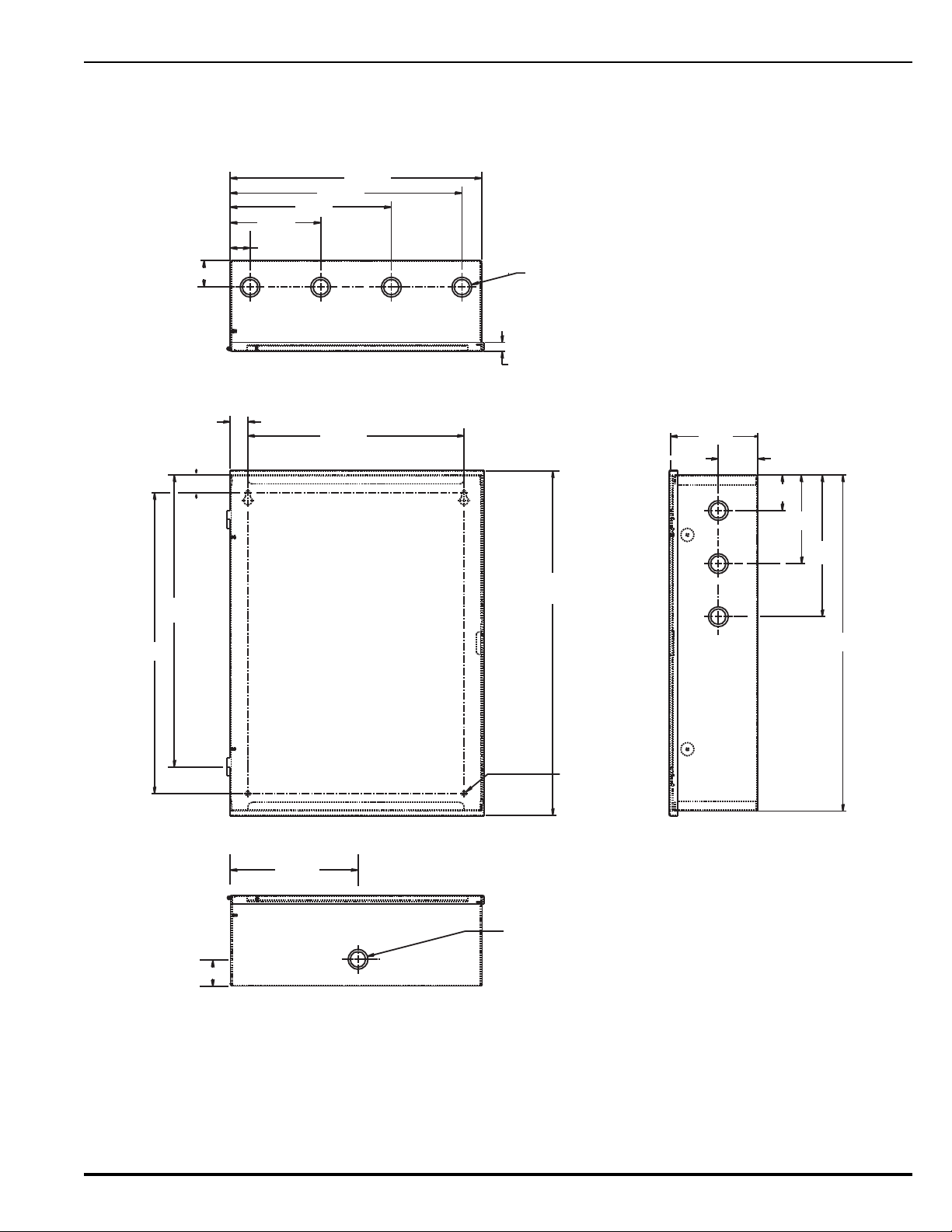
2-4 MOUNTING THE CABINET/ENCLOSURE
19.456
0.281 Dia. Holes
Typ (2) Places
17.000
16.500
1.000
1.000
12.250
1.500
1.12
5.12
9.12
13.12
14.25
1/2" (0.875 Dia) 3/4" (1.125 Dia)
Combination Knockouts
(4) Located on Top
(3) Located In-Line on Two Sides
0.500
Cover Outside
5.000
2.25
2.00
5.00
8.00
19.00
Note: All dimensions are in inches.
1.500
7.12
Top View
Bottom View
Side View
1/2" (0.875 Dia) 3/4" (1.125 Dia)
Combination Knockout
The control unit can be surface or semi-flush mounted. Figure 2-1 shows the control-unitenclosure dimensions. All dimensions are in inches.
P/N 06-236530-001 2-5 August 2013
Figure 2-1. Enclosure Dimensions
Page 48
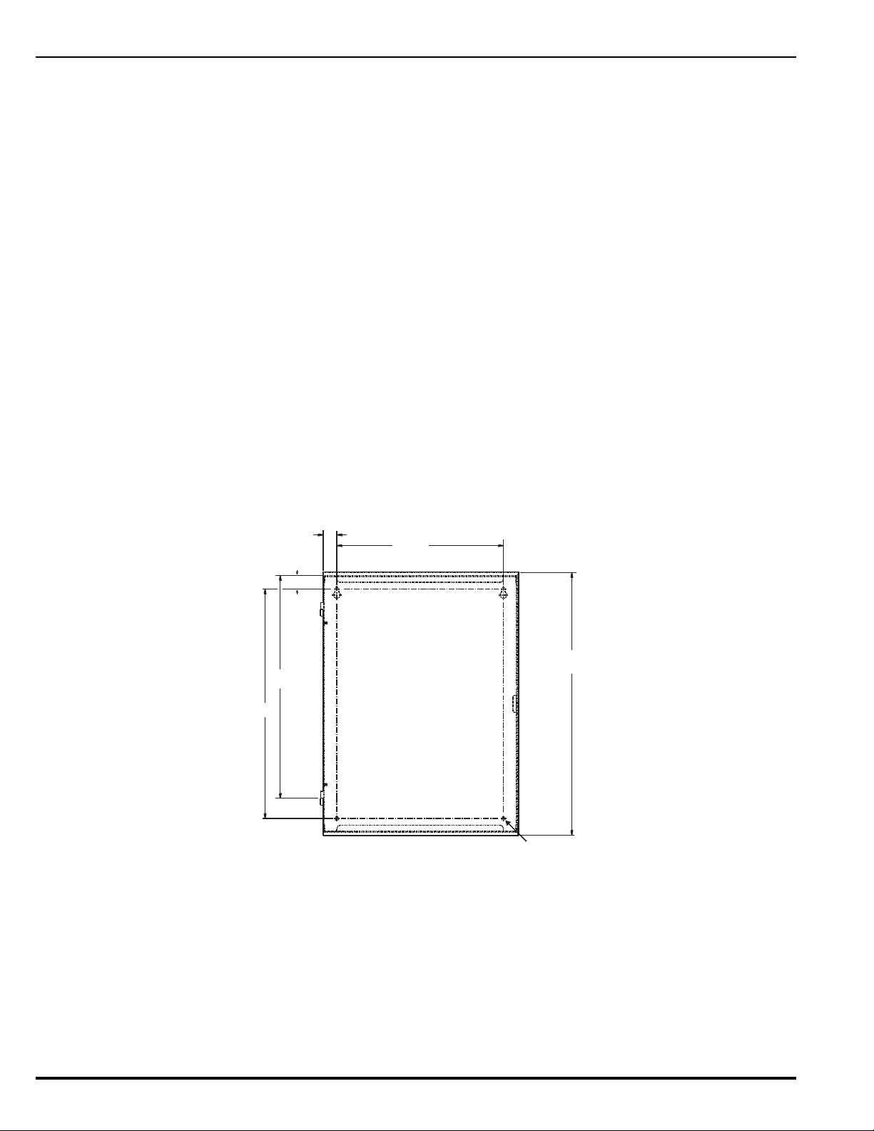
2-4.1 Preparing the Enclosure for Wall Mounting
19.456
0.281 Diameter
Holes Typ (2) Places
17.000
16.500
1.000
1.000
12.250
For either mounting configuration:
1. Remove the keys from the envelope taped to the top of the enclosure and open the
door to the control unit.
2. Disconnect the ground wire that connects the enclosure door to the back box.
3. Remove the control unit front door first by unlocking it and rotating the door
approximately 90° from its closed position.
4. Lift up the door to allow the door’s hinge pins to clear the mating-hinge sockets on
the back box.
5. Remove the separately packaged power supply, printed-circuit board, and plastic
bag (i.e., ship kit) containing installation hardware, and set them and the front door
aside in a safe location to prevent damage.
6. Locate the top of the cabinet approximately 66” above the floor so that the control
unit’s display is positioned at a convenient height for viewing system events and for
entering operator commands.
2-4.2 Surface Mounting
To surface mount the control unit:
1. Mark and pre-drill holes for four mounting bolts using the dimensions shown in
Figure 2-2. The installer must supply the mounting bolts (up to size 1/4-20). There
are two holes and two keyhole slots in the enclosure’s rear panel that serve as a
template for surface mounting.
Figure 2-2. Back Box Mounting Dimensions
2. Insert the upper two fasteners in the wall. Leave approximately 1/4” protruding
for both screws.
3. Slip upper keyholes of the back box over the two protruding screws. Tighten the
screws.
4. Insert and tighten the two lower screws.
5. Attach wiring conduit to the enclosure via the enclosure knockouts, and pull the
required number of wires through the conduit to the enclosure. Leave
August 2013 2-6 P/N 06-236530-001
Page 49
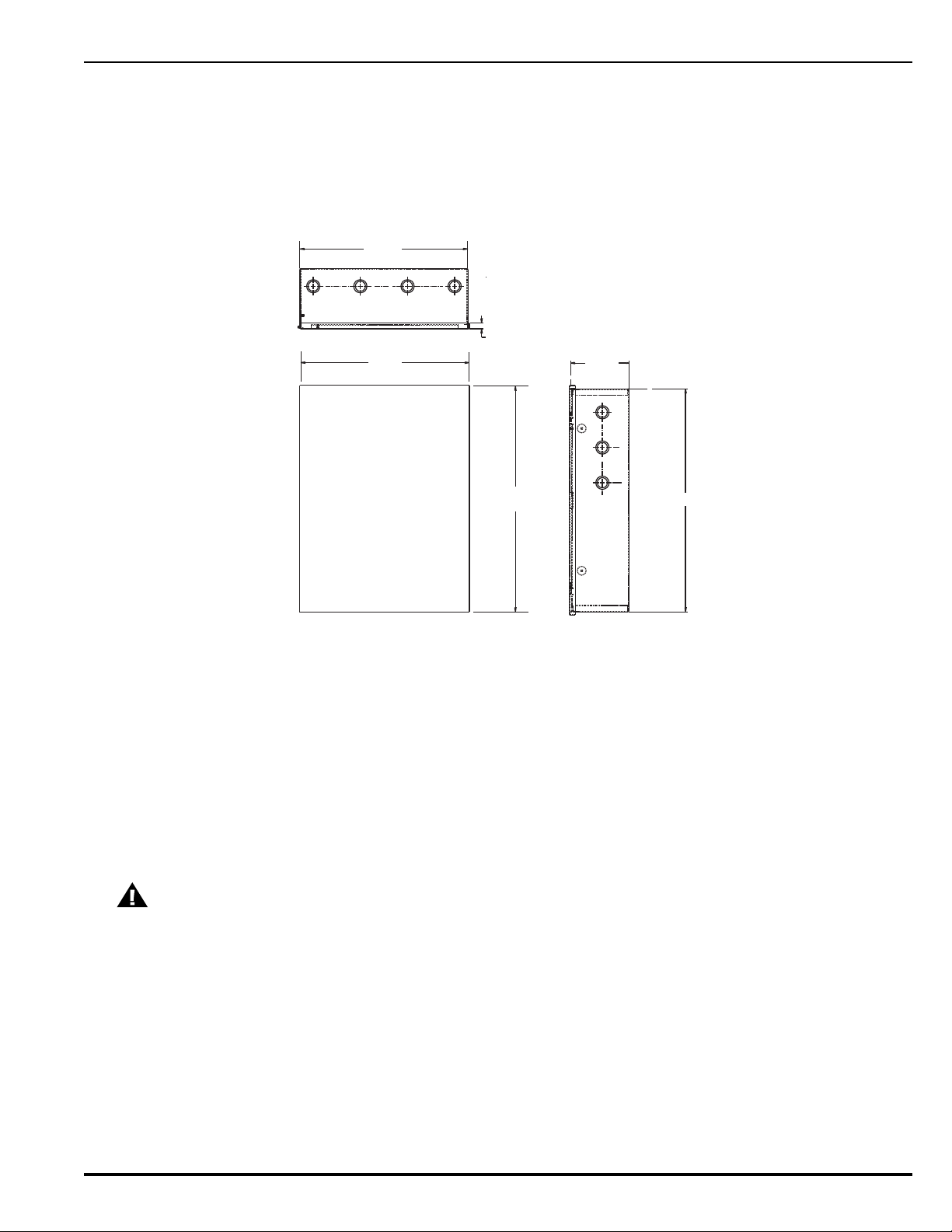
approximately 2 to 3 feet of wire length in the enclosure for future internal
19.00
14.25
14.25
0.500 Cover
Outside
5.000
19.00
Wall Cutout
connections.
2-4.3 Semi-Flush Mounting
To semi-flush mount the control unit:
1. Cut and plumb an opening approximately 14.25” wide by 19” high in the wall on
which the control unit will be semi-flush mounted.
Figure 2-3. Semi-Flush Mounting Dimensions
2. Position and plumb the back box in the opening made in Step 1. Ensure that the
front edge of the back box is at least 3/4 inches from the surface of the wall. Refer
to Figure 2-3. Secure the back box to the wall with appropriate mounting bolts (up
to size 1/4-20).
3. Attach wiring conduit to the enclosure through the enclosure knockouts, and pull
the required number of wires through the conduit to the enclosure. Leave
approximately 2 to 3 feet of wire length in the enclosure for future internal
connections.
2-5 INSTALLING THE POWER SUPPLY
Use a ground strap to prevent static discharge that could damage the power
CAUTION
Note: Make sure the control unit location is dry and that the enclosure is free of construction
supply.
dust and metal shavings prior to installing the power supply.
1. Remove the power supply unit from its shipping carton.
2. Connect the wire harness that is packaged in the installation kit. Next connect the fork end
of the green ground wire that is also part of the installation kit to the earth-ground terminal
of the power supply. Refer to Figure 2-4 for wire harness and earth-ground connections.
P/N 06-236530-001 2-7 August 2013
Page 50
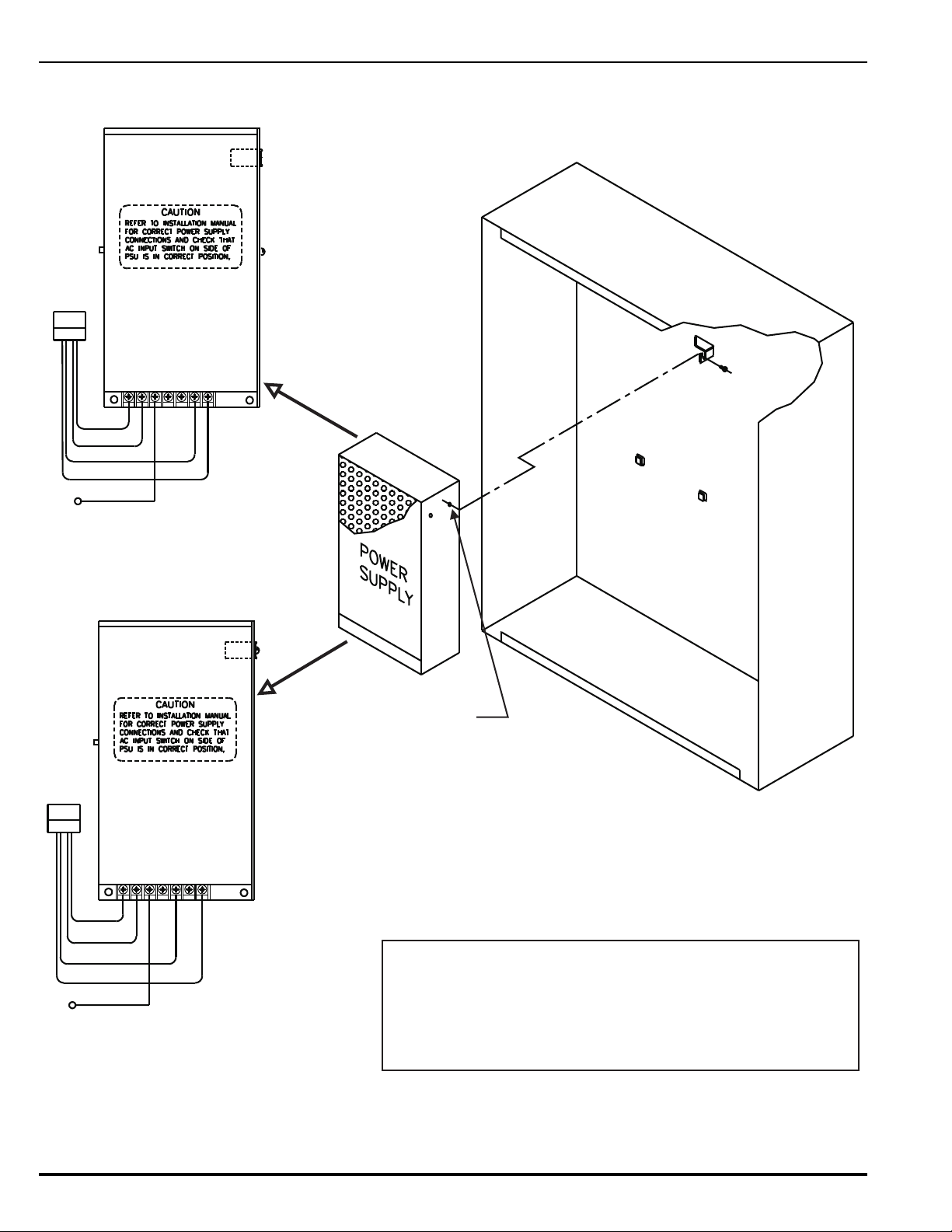
Fastening Tab
for Screw
Retention Tabs
Typ (2)
Wiring-Harness
Connections
Ground Wire from Installation Kit
Connect to lower earth-ground stud on lefthand side of enclosure.
Threaded hole for
3x10mm
mounting screw.
GND
NEUTRAL
LINE
-24V
+24V
BLK
RED
WHT/BLK
WHT
GND
NEUTRAL
LINE
+V
+V
BLK
RED
WHT/BLK
WHT
-V
-V
Or
Wiring-Harness
Connections
Ground Wire from Installation Kit
Connect to lower earth-ground stud on lefthand side of enclosure.
ATTENTION !
The Control Unit is supplied with one of two equivalent power supplies.
Compare the terminal block wiring legend on the provided power supply
with the diagrams at left and connect the wiring harness as shown in the
applicable diagram.
GRN
GRN
August 2013 2-8 P/N 06-236530-001
Figure 2-4. Power Supply Unit
Page 51
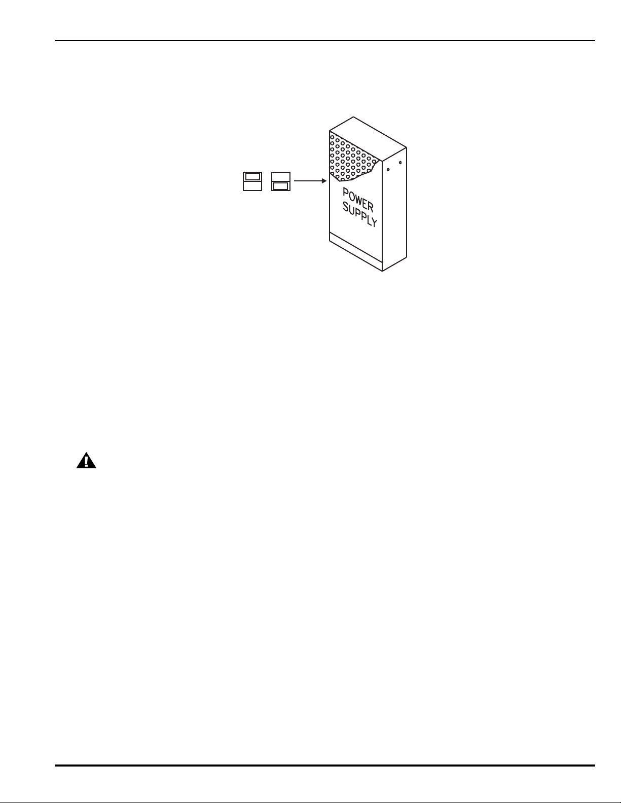
3. Locate the 3 x 10 mm mounting screw in the installation kit and thread it part way into the
115 V
230 V
lower of the two threaded holes of the power supply unit. See Figure 2-4.
4. Ensure that the power supply unit AC-input-voltage selector switch is set to the proper
position for either 120 Vac or 220/240 Vac. See Figure 2-5.
Figure 2-5. Primary Power Selection Switch
5. Locate the two power-supply-unit retention tabs and the fastening tab in the
enclosure’s back panel.
6. Position the power-supply unit with the wire harness down, and then slide it onto the retention
tabs. The 3 x 10 mm mounting screw should slide into the slot of the fastening tab at the same
time.
7. Tighten the screw onto the fastening tab.
8. Connect the ring end of the power supply’s green ground wire to the lower earth-ground
stud on the left side of the enclosure.
2-6 INSTALLING THE PRINTED CIRCUIT BOARD (PCB)
Use a ground strap to prevent static discharge that could damage sensitive
CAUTION
components on the main PCB.
Refer to Figure 2-6 before you unpack and install the PCB within the enclosure.
Note: Make sure the control unit location is dry and that the enclosure is free of construction
dust and metal shavings prior to installing the PCB.
P/N 06-236530-001 2-9 August 2013
Page 52
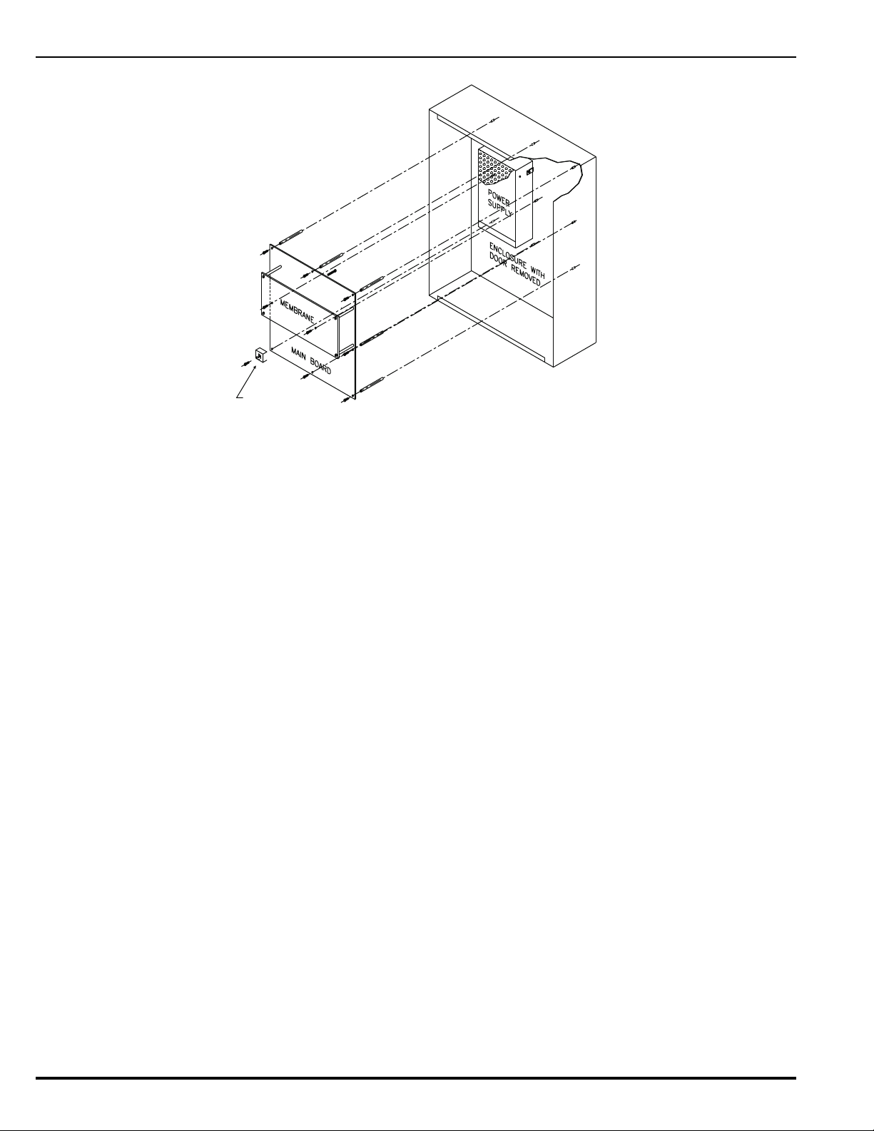
Figure 2-6. PCB Installation
AC Protective Cover
(with standoff)
1. Locate the nine (9) 2-1/4” aluminum standoffs in the installation kit and screw one securely
into each of the nine (9) threaded PEMs in the back surface of the enclosure.
2. Slip on a wrist ground strap and clip the ground strap to the earth ground in the enclosure.
Do not remove the PCB from its shipping carton unless you have established a common
earth-ground potential among yourself, the enclosure, and the PCB’s shipping carton.
3. Remove the PCB from its shipping carton and position each of its nine (9) mounting holes
over one of the aluminum standoffs so that the AC-input terminal block is in the lower-left
corner.
4. Secure the PCB to the standoffs using the eight (8) short washer-and-screw assemblies
supplied in the installation kit.
Note: Do not tighten the screws at this time.
The PCB mounting hole in the lower left corner utilizes a longer nylon screw that also holds
the AC Safety Cover in place. See Section 2-7.1.
5. Refer to Figure 2-7 and place the free end of the longer of the two factory-installed EarthGround wires under the screw assembly of the main printed-circuit board as shown before
tightening. Tighten the remaining eight screws. Be careful not to over-tighten.
6. Plug the harness from the power-supply unit into Connector J12 in the lower-left-hand
corner of the PCB.
August 2013 2-10 P/N 06-236530-001
Page 53
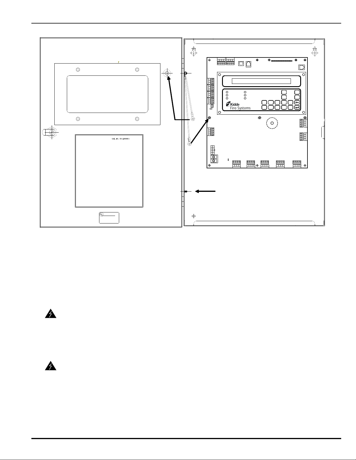
Figure 2-7. PCB-to-Cabinet Grounding Diagram
AC POWER
ALARM
PRE-ALARM
SYSTEM TROUBLE
SUPERVISORY
SILENCE
SYSTEM
ACKNOW LEDGE
SYSTEM
RESET
SILENCE
SCROLL
12345
67890
Combo 2
TB6TB7
Combo 1
TB2
Aux 24 VDC
TB11
Release 2
TB12
Release 1
Batt Out
TB3
TroubleRel ay 3Relay 1 Relay 2
1234 1234 1234 1234 1234
120
240
TB13
AC IN
NL
PSU
J12
+
+
-
-
CNCNO
CNCNO
CNCNOCNCNO
1234
TB5
NAC 1
TB14
1234
NAC 2
RS-232 A
J8
J5
J3
J6
TB15
USB B
RS 485SLC
TB1
4321 4321
Style 4
S2
J10
RS-232 B
TB8 TB9 TB10TB4
Attach longer ground wire
to PCB with washer-andscrew assembly.
Attach shorter ground
wire to enclosure
door with washer-
and-screw assembly.
Earth-ground terminal for
power supply and green
wire of AC supply
2-7 AC AND DC POWER CONNECTIONS
The control unit uses commercially- or end-user-provided AC power as the primary power
source, together with a 24 Vdc standby battery (when required by local codes and/or Authority
Having Jurisdiction [AHJ] requirements).
Two different sources of power can be connected to the control unit. Disconnect
both sources of power and critical components such as control heads for special
WARNING
extinguishing systems and addressable pilot relays controlling facility-power
shutoff before servicing the control unit. The control unit and associated
equipment may be damaged by connecting wiring while the control unit is
energized.
Use caution when connecting power. High-voltage and AC-powered circuits are
present in the control unit. Be sure to adequately ground the control unit to
WARNING
reduce the risk of electrical shock.
2-7.1 AC Power Connection
The primary AC power for the ARIES Control Unit is 120 Vac, 50/60 Hz, 3.2 A or
220/240 Vac, 50/60Hz, 1.6A. The default power configuration is 120 Vac and will require
resetting for 220/240 Vac operation. Configuration of primary AC power requires that the
power-selection switch on the side of the power supply be set correctly before the power
P/N 06-236530-001 2-11 August 2013
Page 54
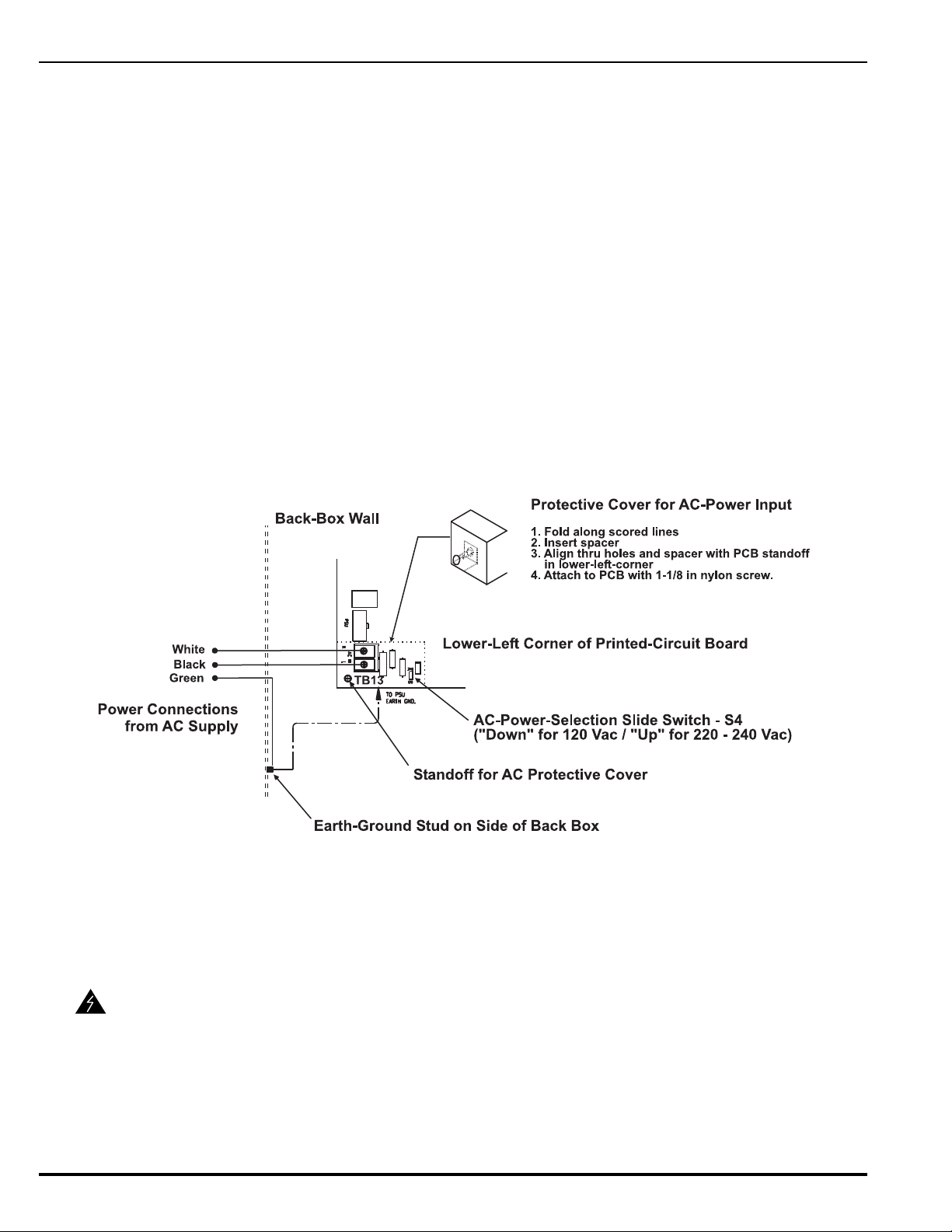
supply is installed in the enclosure, and that Switch S4 in the lower-left corner of the
printed-circuit board be set to agree with the primary AC power being used. Refer to
Paragraph 2-5.
Over-current protection for this circuit must comply with Article 760 of the National
Electrical Code (NEC) and/or the local electrical code. Use a grounded power cord of #14
AWG or larger wire with 600 Vac rating to make the AC power connection to the control
unit. Follow the procedure below to make AC power connections.
1. Disconnect all power sources from the control unit and the AC power cord
2. Run AC-input wiring to the left side of the enclosure, and preferably, use the lowest
of the three knock-outs on the left-hand side as the entry point for primary power.
3. Connect the primary power earth-ground (green) wire to the lower Earth Ground
stud on the left inside of the enclosure.
4. Connect the neutral (white) wire to the Main Circuit Board Terminal Block TB13
labeled ‘N’ (Neutral).
5. Connect the hot (black) wire to the Main Circuit Board Terminal Block TB13 labeled
‘L’ (Line).
6. Remove the AC Safety Cover, 3/4” nylon spacer, and 1-1/8” nylon screw from the
installation kit. Fold the cover along its scored lines and install it over the AC power
input terminals, as shown in Figure 2-8.
Figure 2-8. Primary-Power Connections
7. Set AC-Power-Selection Switch S4 on the main printed-circuit board to correspond
to the AC input power (120 Vac, 50/60 Hz, or 220/240 Vac, 50/60 Hz) being used.
2-7.2 DC Power Connection
Batteries contain sulfuric acid that can cause severe burns to the skin and eyes
and can damage clothing. Immediately flush areas of the skin or eyes that have
WARNING
August 2013 2-12 P/N 06-236530-001
been contacted with sulfuric acid for 15 minutes with water and seek medical
attention promptly.
Note: Observe polarity when connecting the battery to the control unit.
To connect the standby battery to the control unit:
Page 55
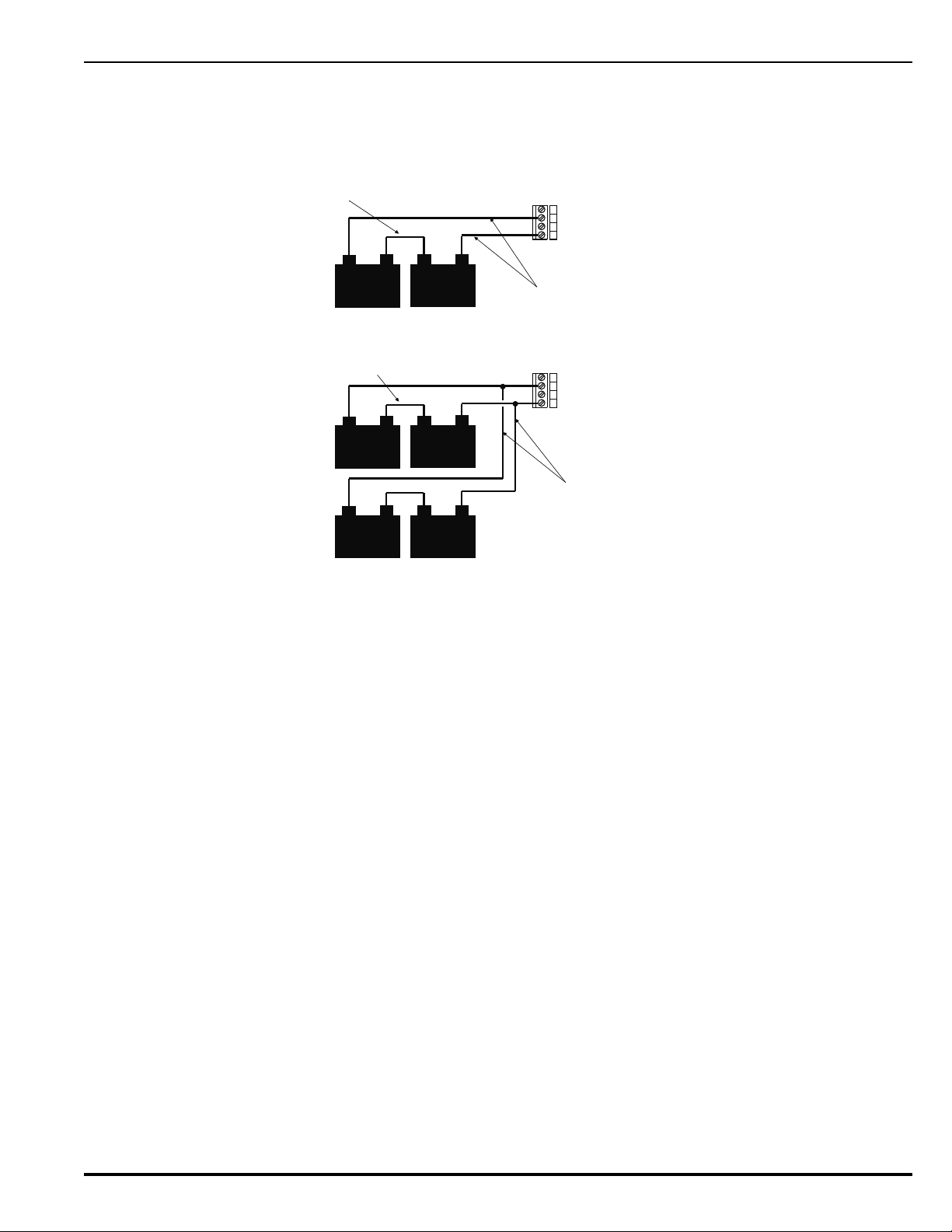
1. Calculate the size of the battery required for the application. Refer to Appendix A
--
12-V Battery
12-V Battery
+
-
+
-
+
+
TB3
Battery Cables
Battery Jumper
--
12-V Battery
12-V Battery
+
-
+
-
+
+
TB3
Battery Cables
Typical (by installer)
Note:
Locate all batteries in a common
battery cabinet or in close-coupled
battery cabinets with all battery
cables in conduit.
Battery Jumper
Typical (by installer)
12-V Battery
12-V Battery
+
-
+
-
Single-Battery Installation
Dual-Battery Installation
for the proper procedure.
2. Connect two 12-volt, series-wired batteries of the required ampere-hour (AH)
capacity to printed-circuit board Terminals TB3 using the battery cable. See
Figure 2-9.
Figure 2-9. Standby Battery Connections
2-8 SIGNALING LINE CIRCUIT
The signaling line circuit (SLC) is the communications path between the ARIES Control Unit and
the SmartOne field devices. The SLC can be wired to meet NFPA 72 Class-A, Style-6 and -7 or
Class-B, Style-4 requirements.
The SLC can accommodate any combination of up to 255 devices, which include SmartOne
automatic initiating devices, monitor modules, relay modules, and control modules.
2-8.1 SLC Wiring Requirements
All SLC wiring must be twisted, unshielded, low-capacitance, fire-alarm-system wire.
Refer to Appendix B for recommended wire types.
2-8.1.1 CLASS-B, STYLE-4 WIRING REQUIREMENTS
The total wiring resistance from the control unit to the end of each individual
branch line cannot exceed 40 ohms. Use the following procedure to determine the
wiring resistance.
1. Short the ends of each branch line one at a time. Measure the resistance
from the terminating points at the control unit to the end of the branch line.
See Figure 2-10.
2. Remove the shorting jumper after each branch-line resistance
measurement.
P/N 06-236530-001 2-13 August 2013
Page 56
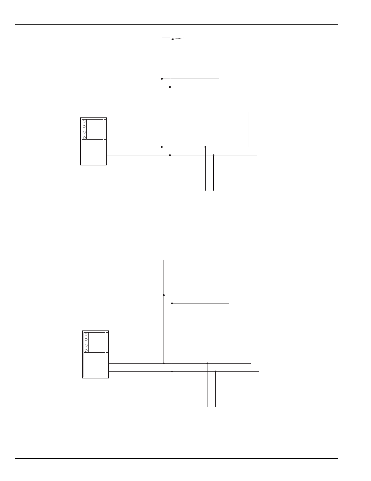
Figure 2-10. Measuring Class-B SLC Wiring Resistance
Jumper
Branch 1
Branch 2
Branch 3
Branch N
Volt-Ohm Meter
Branch 1
Branch 2
Branch 3
Branch N
Capacitance Meter
The total wiring capacitance cannot exceed 0.5 F. Use the following procedure to
determine the wiring capacitance.
1. Ensure that the ends of each branch line are open circuited.
2. Measure the capacitance from the terminating points at the control unit
using a capacitance meter. See Figure 2-11.
Figure 2-11. Measuring Class-B SLC Wiring Capacitance
Figure 2-12 shows typical wiring for a Class-B, Style-4 signaling line circuit. Make
sure that the SLC-Selector Switch S2 is moved to the left into the Style-4 position.
Refer to Figure 1-3.
August 2013 2-14 P/N 06-236530-001
Page 57
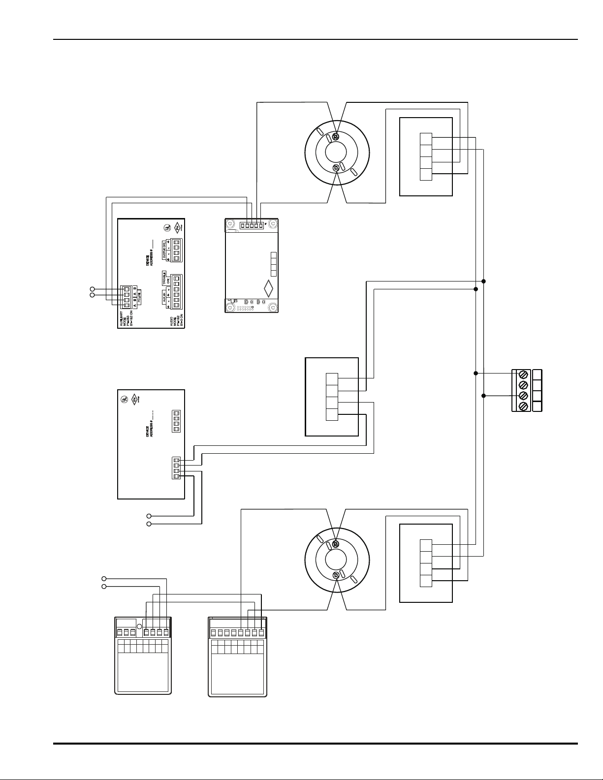
Note: Isolator modules are not required for a Class-B, Style-4 signaling line
RET RET24 V 24 V
OUT IN
RET RET24 V 24 V
OUT IN
4321
3
7
3
7
765
4321
PC PC PC PC
(+) (-) (+) (-)
N/C
COM
N/O
7654321
PC PC PC PC
(+) (-) (+) (-)
8
ASWB
SW
(+)
LED
(-)
LED
AO Relay Module
AI Monitor Module
Detector Base
Isolator Module
(Single-Gang Mount)
Isolator Module
(Single-Gang Mount)
AAM AlarmLine Module
Isolator Module
(Single-Gang Mount)
Detector Base
PALM Monitor Module
BABA
INOUT
PC LINE
BLU
RED
WHT
ORN
ASM Signal Module
To Next Device To Next Device
To Next Device
ADDRESS
FM
APPROVED
IN
OUT
RXTX
RXTX
GND
Branch 1
Branch 2
Branch N
SLC Terminals on
Printed-Circuit Board
(TB1)
Notes:
1. Move SLC-Style Switch S2 to the left into the Style-4 position.
2. Each isolator module creates a 0.12-V voltage drop.
RET RET24 V 24 V
OUT IN
Caution:
Do not use looped wire under terminals of
detector bases. Break SLC wire run to provide
supervision of connections
.
circuit. A maximum of 30 SmartOne devices can be installed between
a pair of isolator modules.
Figure 2-12. Class-B, Style-4 Signaling Line Circuit
P/N 06-236530-001 2-15 August 2013
Page 58
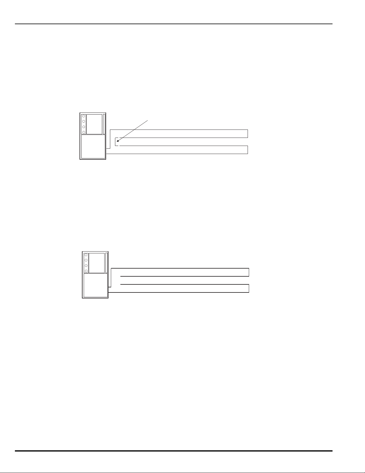
2-8.1.2 CLASS-A, STYLE-6 WIRING REQUIREMENTS
Jumper
Out Leg
Return Leg
Volt-Ohm Meter
Out Leg
Return Leg
Capacitance Meter
Note: The following resistance reading MUST be taken PRIOR to the installation
of any peripheral device.
The total wiring resistance from the start of the “Out” leg to the end of the
“Return” leg cannot exceed 40 ohms. Use the following procedure to determine
the wiring resistance.
1. Short the “Out” and “Return” legs as shown in Figure 2-13. Measure the
resistance using the other two terminating points at the control unit
2. Remove the shorting jumper after the resistance measurement.
Figure 2-13. Measuring Class-A SLC Wiring Resistance
The total wiring capacitance cannot exceed 0.5 F. Use the following procedure to
determine the wiring capacitance.
Note: The following capacitance reading MUST be taken PRIOR to the installation
of any peripheral device.
1. Measure the capacitance using the wiring that will connect to control unit
terminals TB1-1 and TB1-3 (Terminals TB1-2 and TB1-4 MUST remain
disconnected from the control unit) as shown in Figure 2-14.
Figure 2-14. Measuring Class-A SLC Wiring Capacitance
Figure 2-15 shows typical wiring for a Class-A, Style-6 signaling line circuit. Make
sure that the SLC-Selector Switch S2 is moved to the right into the Style-6
position. Refer to Figure 1-3
Note: Isolator modules are not required for a Class-A, Style-6 signaling line
circuit. A maximum of 30 SmartOne devices can be installed between a
pair of isolator modules.
August 2013 2-16 P/N 06-236530-001
Page 59
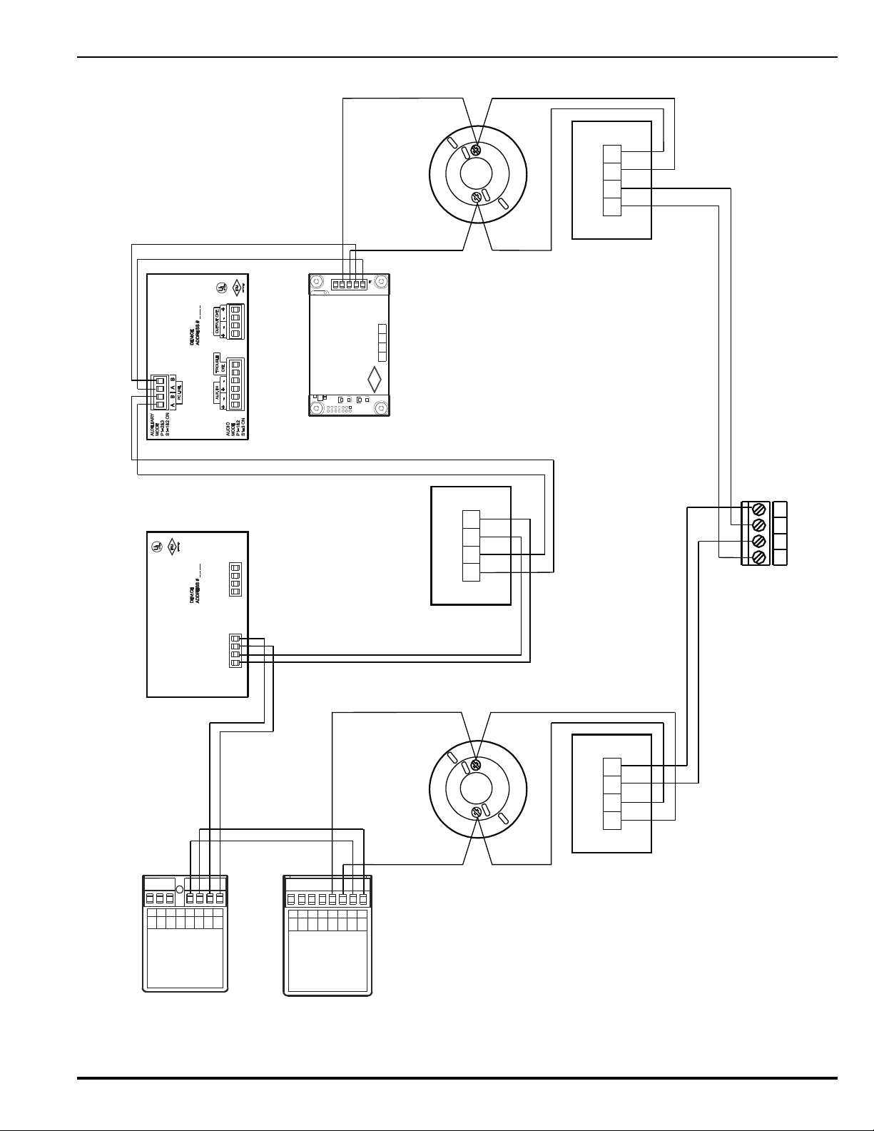
RET RET24 V 24 V
OUT IN
RET RET24 V 24 V
OUT IN
4321
3
7
3
7
765
4321
PC PC PC PC
(+) (- ) (+) (-)
N/C
COM
N/O
7654321
PC PC PC PC
(+)(-) (+)(-)
8
ASWB
SW
(+)
LED
(-)
LED
AO Relay Module
AI Monitor Module
Detector Base
Isolator Module
(Single-Gang Mount)
AAM AlarmLine Module
Isolator Module
(Single-Gang Mount)
Detector Base
PALM Monitor Module
BABA
INOUT
PC LINE
BLU
RED
WHT
ORN
ASM Signal Module
ADDRESS
FM
APPROVED
IN
OUT
RXTX
RXTX
GND
SLC Terminals on
Printed-Circuit Board
(TB1)
Notes:
1. Move SLC-Style Switch S2 to the right into the Style-6 position.
2. Each isolator module creates a 0.12-V voltage drop.
RET RET24 V 24 V
OUT IN
Isolator Module
(Single-Gang Mount)
Caution:
Do not use looped wire under terminals of
detector bases. Break SLC wire run to provide
supervision of connections
.
Figure 2-15. Class-A, Style-6 Signaling Line Circuit
P/N 06-236530-001 2-17 August 2013
Page 60
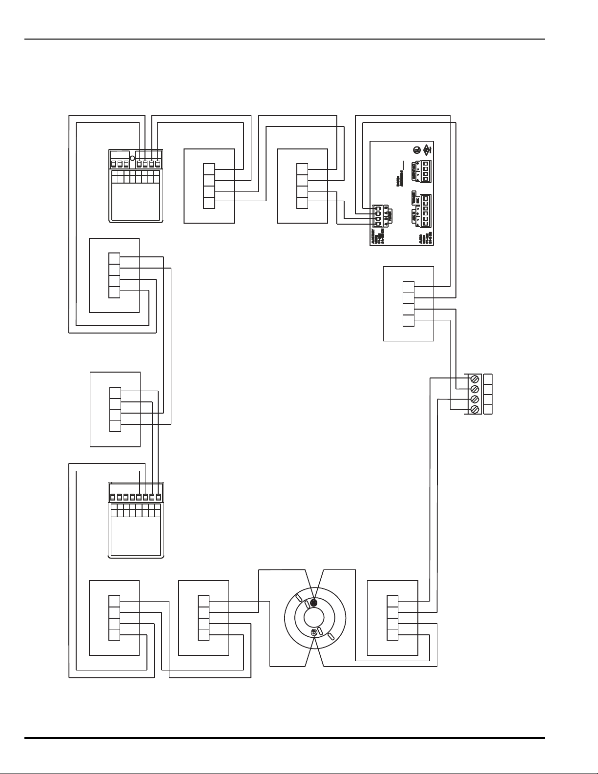
2-8.1.3 SPECIAL CLASS-A, STYLE-7 REQUIREMENTS
RET RET24 V 24 V
OUT IN
RET RET24 V 24 V
OUT IN
4321
765
4321
PC PC P C P C
(+) (-) (+) (-)
N/C
COM
N/O
7654321
PC PC PC PC
(+) (-) (+) (-)
8
ASWB
SW
(+)
LED
(-)
LED
AO Relay Module
AI Monitor Module
Single-Gang-Mount
Isolator Module
(Typical)
See Note 2
ASM Signal Module
SLC Terminals on
Printed-Circuit Board
(TB1)
RET RET24 V 24 V
OUT IN
Notes:
1. All wiring shall be installed in conduit.
2. Install isolator modules as close as possible to protected devices (max. 20 feet).
3. Move the SLC-Style Switch S2 to the right into the Style-6 position.
4. Each isolator module creates a 0.12-V voltage drop.
RET RET24 V 24 V
OUT IN
RET RET24 V 24 V
OUT IN
3
7
Detector Base
Caution:
Do not use looped wire under terminals of
detector bases. Break SLC wire run to provide
supervision of connections
.
RET RET24 V 24 V
OUT IN
RET RET24 V 24 V
OUT IN
RET RET24 V 24 V
OUT IN
A Class-A, Style-7 signaling line circuit requires a pair of isolator modules for each
SmartOne device as shown in Figure 2-16. Make sure that the SLC-Selector
Switch S2 is moved to the right into the Style-6 position. Refer to Figure 1-3.
Figure 2-16. Class-A, Style-7 Signaling Line Circuit
August 2013 2-18 P/N 06-236530-001
Page 61
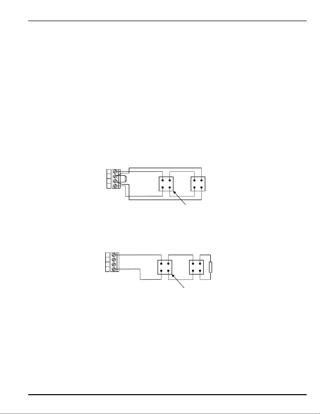
2-9 NOTIFICATION APPLIANCE CIRCUITS
-
+
-
+
4321
TB5
or
TB14
NAC 1orNAC 2
Polarized Notification Appliance
(Typical)
Supervised and Power-Limited
End-of-Line Resistor
10k +/- 10%, 0.5W
-
+
-
+
4321
End-of-Line Resistor
10 k +/- 10%, 0.5 W
NAC 1orNAC 2
TB5
or
TB14
Polarized Notification Appliance
(Typical)
Supervised and Power-Limited
The ARIES Control Unit has two notification-appliance circuits (NACs) that are labeled NAC1 and
NAC2. These circuits have field-wiring connections that terminate at TB5 and TB14, respectively.
Each NAC can supply up to 1.5 A of current at a nominal 24 Vdc for polarized notification
appliances. Total current output of the ARIES power supply must not exceed 5.4 A.
Both circuits are supervised, power limited, and are compatible with conventional, UL-Listed, 24Vdc notification appliances. They can also be used with the following synchronizable horns
and strobes:
• MT Series Multi-Tone Horns and Horn/Strobes
• NS Series Horn/Strobes
• NH Series Horns
• RSS(P) Series Strobes
The NS Series notification appliances provide the option to use silenceable horns and nonsilenceable strobes on the same NAC. Refer to the ARIES Programmer’s Guide to configure one
or both NACs for use with the NS Series notification appliances.
Figure 2-17 shows typical wiring for a Class-A, Style-Z notification appliance circuit.
Figure 2-17. Class-A, Style-Z Notification-Appliance Circuit
Figure 2-18 shows typical wiring for a Class-B, Style-Y notification appliance circuit.
Figure 2-18. Class-B, Style-Y Notification-Appliance Circuit
P/N 06-236530-001 2-19 August 2013
Page 62
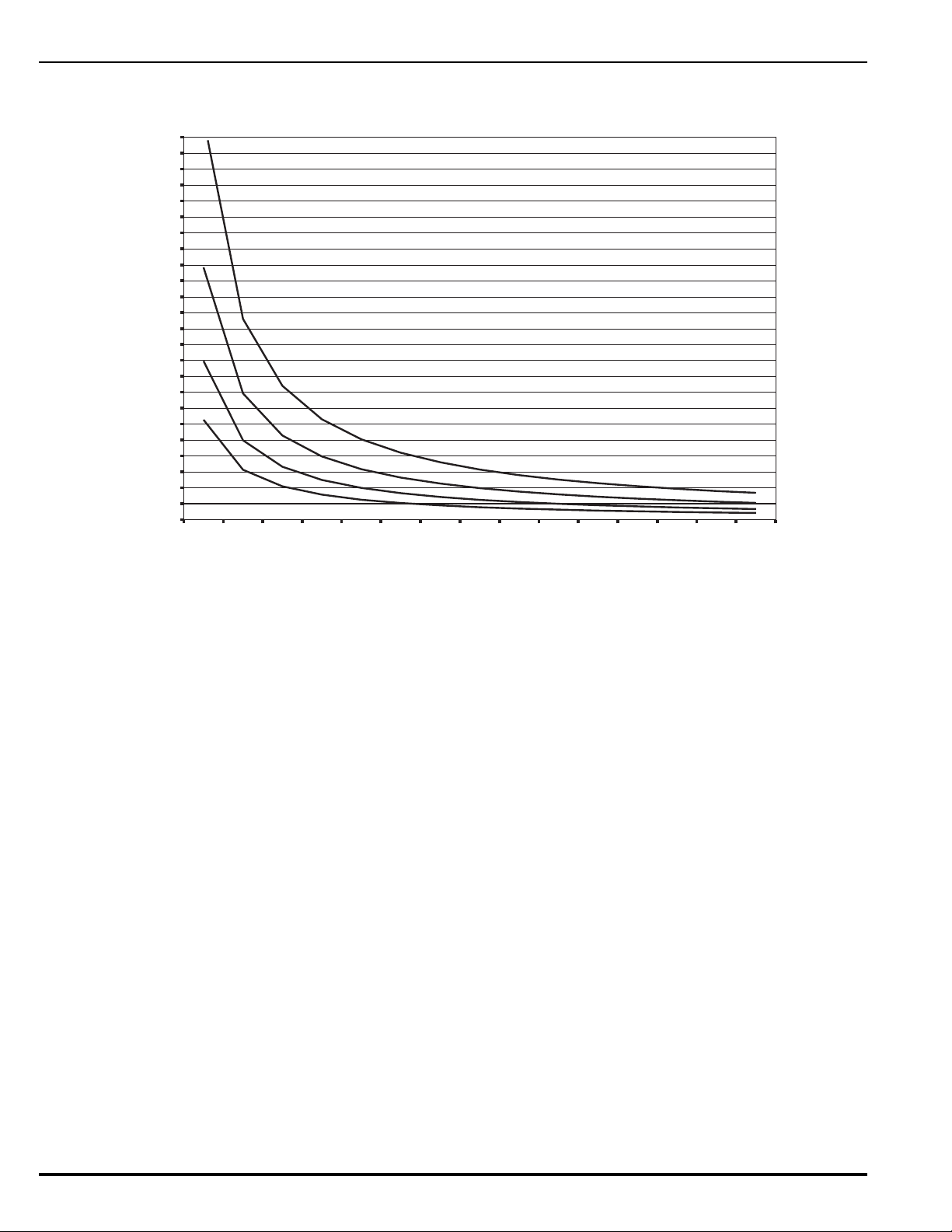
Use Figure 2-19 to estimate the maximum length of wire as a function of notification-appliance
0
500
1000
1500
2000
2500
3000
3500
4000
4500
5000
5500
6000
6500
7000
7500
8000
8500
9000
9500
10000
10500
11000
11500
12000
0.1 0.2 0.3 0.4 0.5 0.6 0.7 0.8 0.9 1 1.1 1.2 1.3 1.4 1.5
NAC Current (A)
#18 AWG
#16 AWG
#14 AWG
#12 AWG
0.0
Maximum NAC Wire Length (Ft.)
current for both NACs.
Figure 2-19. Wiring Length vs. Notification-Appliance Current
2-10 COMBINATION CIRCUITS
The ARIES Control Unit has two combination circuits that can be used either as notificationappliance circuits (NACs) or as releasing circuits for solenoid valves. The combination circuits
are labeled Combo1 and Combo2. These circuits have field-wiring connections that terminate at
TB7 and TB6, respectively.
2-10.1 Combination Circuits used as NACs
Each combination circuit can supply up to 1.5 A of current at a nominal 24 Vdc for
polarized notification appliances when configured as a NAC. Total current output of the
August 2013 2-20 P/N 06-236530-001
ARIES power supply must not exceed 5.4 A.
Both combination circuits are supervised and power limited when configured as NACs.
They are compatible with conventional, UL-Listed, 24-Vdc notification appliances. They
can also be used with the following synchronizable horns and strobes:
• MT Series Multi-Tone Horns and Horn/Strobes
• NS Series Horn/Strobes
• NH Series Horns
• RSS(P) Series Strobes
The NS Series notification appliances provide the option to use silenceable horns and
non-silenceable strobes on the same NAC. Refer to the ARIES Programmer’s Guide to
configure one or both combination circuits as NACs and to configure them for use with
the NS Series notification appliances.
Page 63
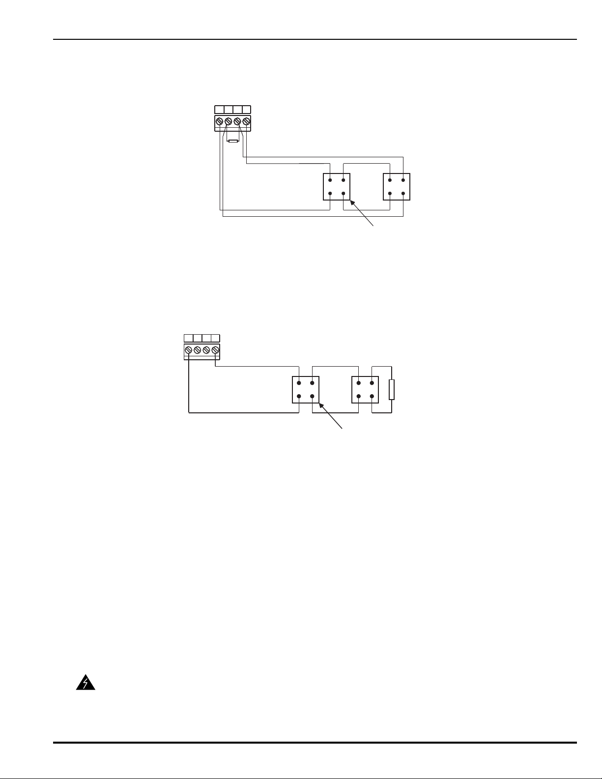
Figure 2-20 shows typical wiring for a combination circuit wired as a Class-A, Style-Z
-
+
-
+
Polarized Notification Appliance
(Typical)
Supervised and Power-Limited
4321
Combo 1 or
Combo 2
End-of-Line Resistor
10k +/- 10%, 0.5W
TB7 or
TB6
-
+
-
+
4321
End-of-Line Resistor
10 k +/- 10%, 0.5 W
Combo 1 or
Combo 2
Polarized Notification Appliance
(Typical)
Supervised and Power-Limited
TB7 or
TB6
notification appliance circuit.
Figure 2-20. Combination Circuit used as Class-A, Style-Z NAC
Figure 2-21 shows typical wiring for a combination circuit wired as a Class-B, Style-Y
notification appliance circuit.
WARNING
Figure 2-21. Combination Circuit used as Class-B, Style-Y NAC
Use Figure 2-19 to estimate the maximum length of wire as a function of notificationappliance current for a combination circuit used as a NAC.
2-10.2 Combination Circuits used as Releasing Circuits
Each combination circuit can be configured as a releasing circuit to activate either one
Kidde control head or one pre-action-sprinkler or deluge-sprinkler valve. Total current
output of the ARIES power supply must not exceed 5.4 A.
Both combination circuits are supervised and power limited when configured as releasing
circuits and when the in-line device, P/N 06-220023-001, is wired in series with the
solenoid valve. The compatible control heads and solenoid valves are listed in
Appendix C. Refer to the ARIES Programmer’s Guide to configure one or both
combination circuits as releasing circuits.
Route non-power limited wiring at least 1/4 inch away from all power-limited wiring.
Ensure that all releasing devices are physically disconnected from the releasing
circuits before performing any system testing or maintenance.
P/N 06-236530-001 2-21 August 2013
Page 64
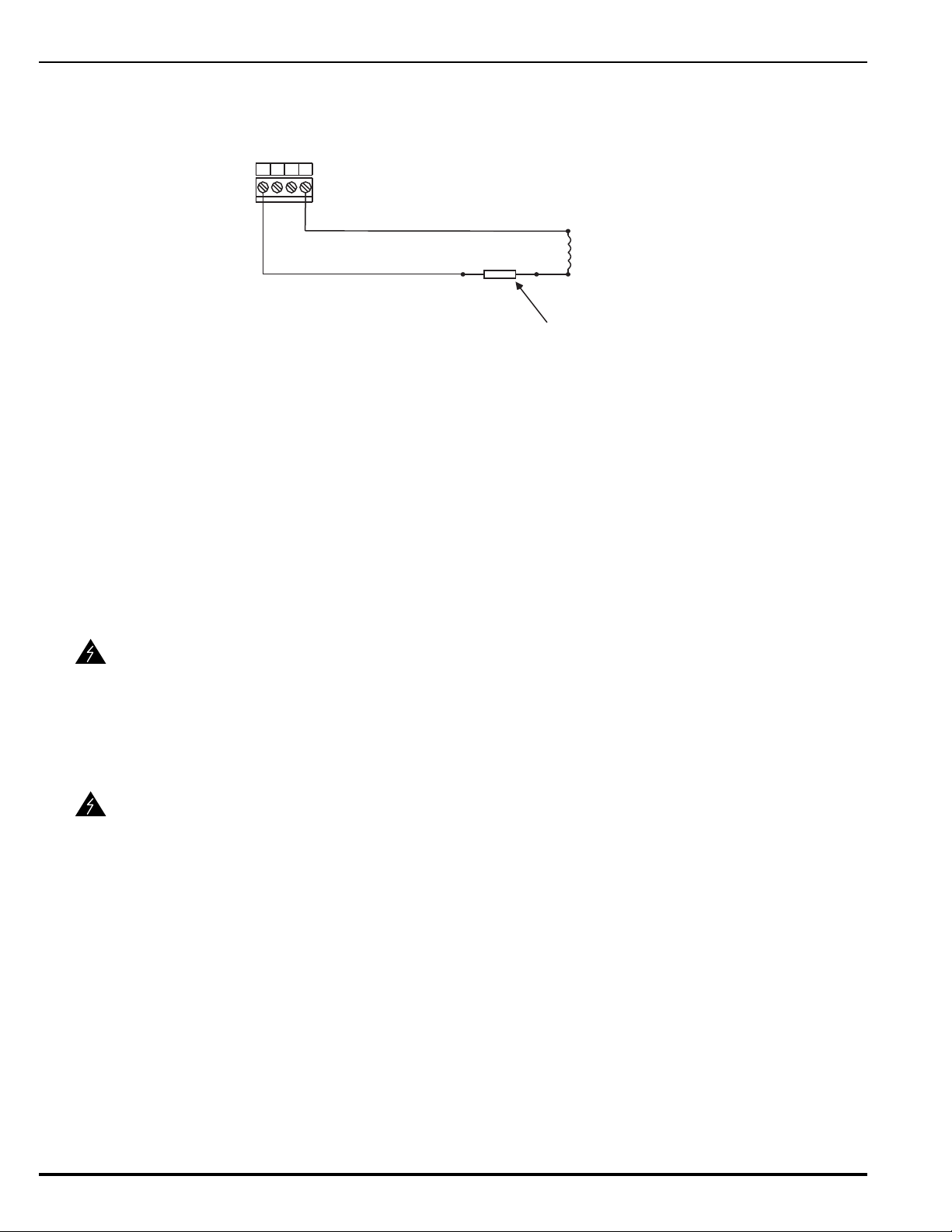
Figure 2-22 shows a combination circuit wired for releasing. Refer to Appendix C for
4321
Combo 1 or
Combo 2
In-Line Releasing Device (P/N 06-220023-001)
(Must be close nippled to solenoid enclosure)
Supervised and Power-Limited
BlkRed
Solenoid
(Refer to Appendix C)
TB7 or
TB6
further information.
Figure 2-22. Combination Circuit used as Releasing Circuit
2-11 RELEASING CIRCUITS
The ARIES has two releasing circuits that can be configured to actuate extinguishing systems
through any of the following ways:
• Single actuator assembly
• Single control head or solenoid valve
• Two series-supervised, parallel-actuated control heads or solenoid valves.
WARNING
WARNING
The release circuits are labeled Release1 and Release2 and have field-wiring connections that
terminate at TB12 and TB11, respectively.
Ensure that all releasing devices are physically disconnected from the releasing
circuits before performing any system testing or maintenance.
2-11.1 Releasing Circuits for Actuator Assembly
Actuator assembly is a non-explosive device. Do not remove the shorting cap
from the cable connector until the field-wiring connections are to be made.
Physical abuse or static-electricity discharge could cause inadvertent actuator
actuation. The installer must establish a common electrical potential with the
actuator assembly before either removing or inserting the shorting cap.
Figure 2-23 shows an actuator assembly connected to a releasing circuit. Each releasing
circuit is capable of actuating one actuator assembly.
August 2013 2-22 P/N 06-236530-001
Page 65
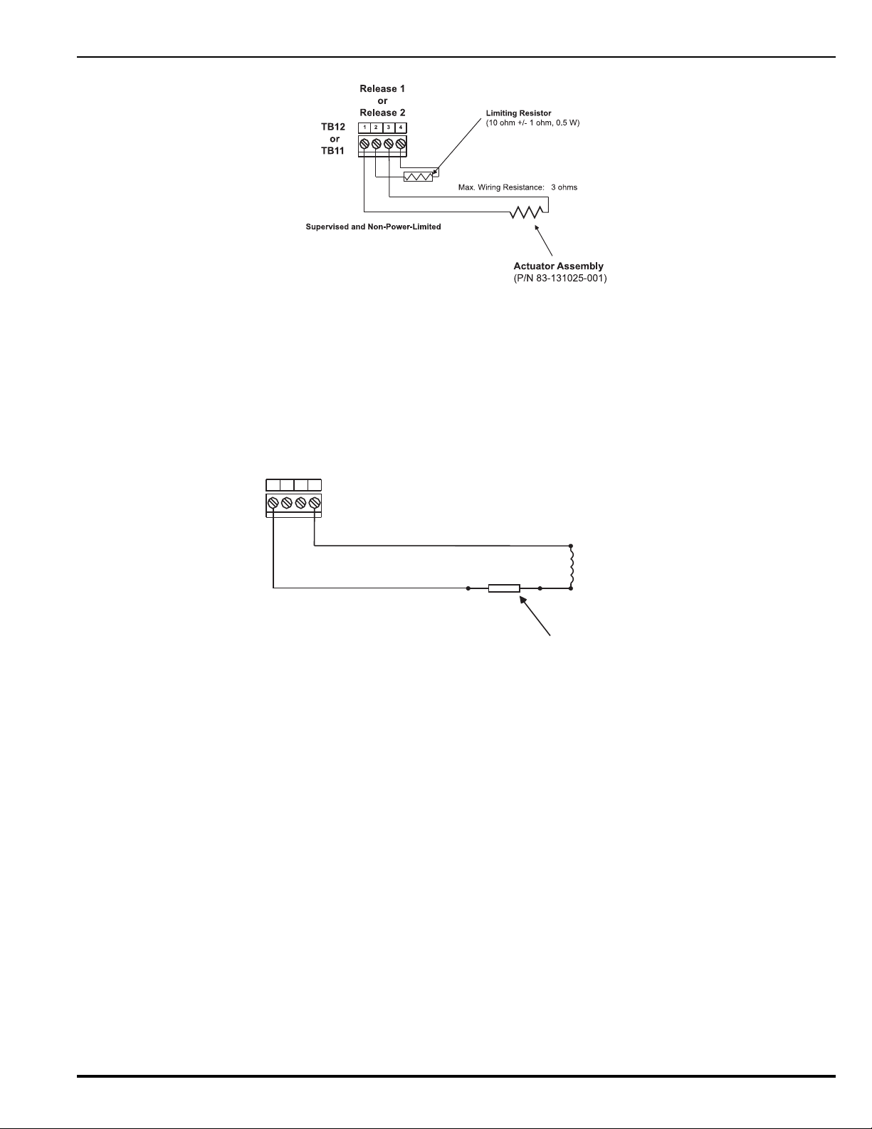
Figure 2-23. Releasing-Circuit Wiring for Actuator
4321
In-Line Releasing Device (P/N 06-220023-001)
(Must be close nippled to solenoid enclosure)
Supervised and Power-Limited
Blk
Red
Solenoid
(Refer to Appendix C)
Release 1 or
Release 2
TB12 or
TB11
2-11.2 Releasing Circuits for Single Control Head or Solenoid Valve
Each releasing circuit can be configured to activate either one Kidde control head or one
pre-action-sprinkler or deluge-sprinkler valve. Total current output of the ARIES power
supply must not exceed 5.4 A. Figure 2-24 shows a releasing circuit wired for singlecontrol-head or single-solenoid-valve actuation.
Figure 2-24. Releasing-Circuit Wiring for Single Solenoid
A releasing circuit is supervised and power limited when the in-line device, P/N
06-220023-001, is wired in series with the single control head or solenoid valve. See
Appendix C for compatible control heads and solenoid valves. Refer to the ARIES
Programmer’s Guide to configure the releasing circuits for single-control-head or singlesolenoid-valve actuation.
Route non-power-limited wiring at least 1/4 inch away from all power-limited wiring.
P/N 06-236530-001 2-23 August 2013
Page 66
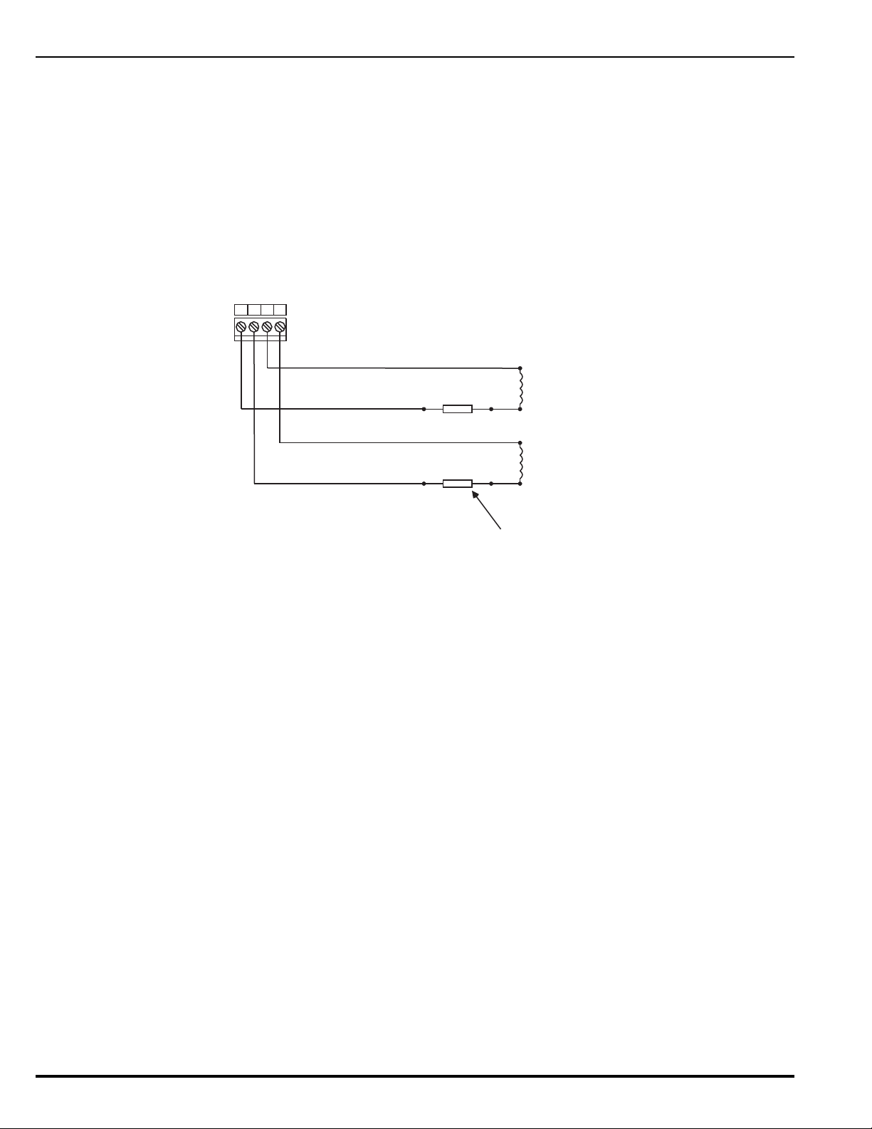
2-11.3 Releasing Circuits for Dual Control Heads or Solenoid Valves
4321
Release 1 or
Release 2
In-Line Releasing Device (P/N 06-220023-001)
(Typ 2)
(Must be close nippled to solenoid enclosure)
Supervised and Power-Limited
Blk
Red
Solenoid
(Refer to Appendix C)
Solenoid
(Refer to Appendix C)
TB12 or
TB11
Blk
Red
Each releasing circuit can be configured to activate either dual Kidde control heads
or dual pre-action-sprinkler or deluge-sprinkler valves that do not exceed the
maximum release circuit current of 2.5A. It can also activate combinations of Kidde
control heads and/or pre-action/deluge sprinkler valves that do not exceed the
maximum release circuit current of 2.5A. Total current output of the ARIES power
supply must not exceed 5.4 A. Figure 2-25 shows a releasing circuit wired for dualcontrol-head or dual-solenoid-valve actuation.
Note: Total combined control head and/or solenoid current must not exceed 2.5A
(continuous output).
Figure 2-25. Releasing-Circuit Wiring for Dual Solenoids
A releasing circuit is supervised and power limited when the in-line device, P/N
06-220023-001, is wired in series with each of the two control heads or solenoid valves.
See Appendix C for compatible control heads and solenoid valves. Refer to the ARIES
Programmer’s Guide to configure the releasing circuits for dual-control-head or dualsolenoid-valve actuation.
Route non-power-limited wiring at least 1/4 inch away from all power-limited wiring. Do
not attach power-limited and non-power-limited wiring to the same terminal block.
2-12 AUXILIARY POWER OUTPUTS
Figure 2-26 shows the auxiliary-power terminals on the main printed-circuit board. Both outputs
are configurable for either resettable or non-resettable operation. Refer to the ARIES
Programmer’s Guide to configure the auxiliary-power outputs.
Both auxiliary-power outputs are power-limited.
Note: Each output 1.0 A (max.) @ 24 Vdc (nominal)
August 2013 2-24 P/N 06-236530-001
Page 67
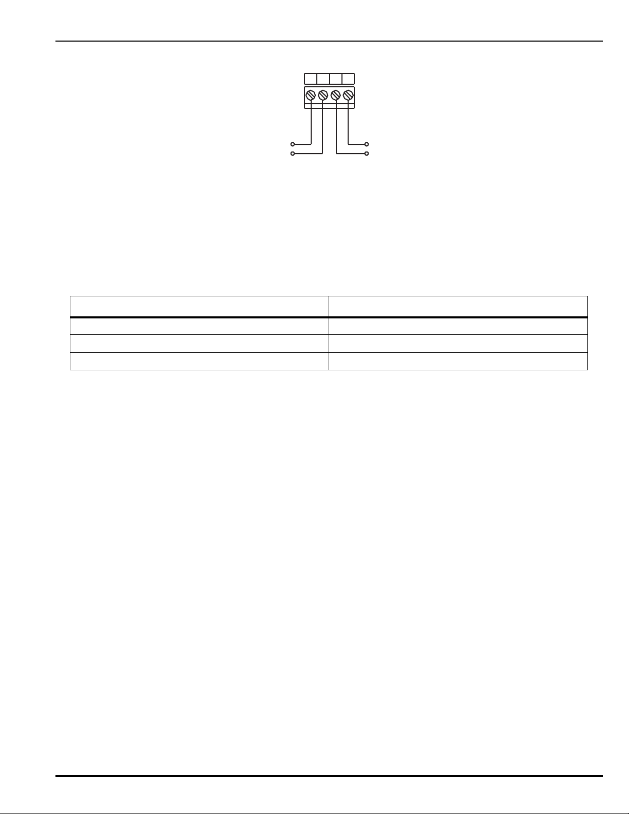
Figure 2-26. Auxiliary-Power Terminals
4321
+
-
-
+
Output No. 2
Output No. 1
TB2
2-13 RS-485 COMMUNICATIONS CIRCUIT
The ARIES Control Unit can communicate with up to 31 peripheral devices via its RS-485
communications circuit. The peripheral devices are listed below, along with the maximum
numbers for each particular type of device. The total number of peripheral devices cannot
exceed 31.
Table 2-1. ARIES Control Unit Maximum Peripheral Devices
Device Maximum Number
Model RDCM Remote Display Control Module 15
Model ATM-L Annunciator Driver Module 16
Model ATM-R Relay Driver Module 16
P/N 06-236530-001 2-25 August 2013
Page 68
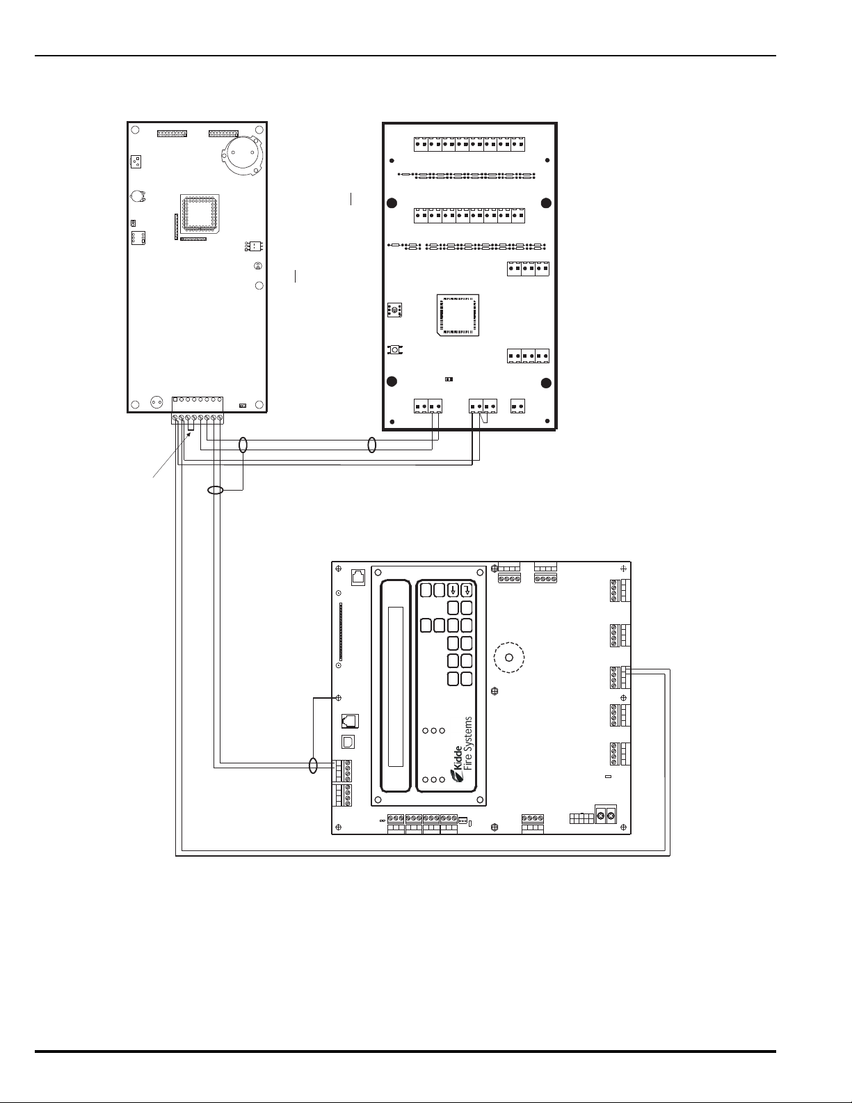
The RS-485 communications circuit is power-limited. Figure 2-27 shows typical interconnections
1234567
8
W2
SW2
DS1
JK1
JK2
SW1
W1
TB1
VR1
VR2
16151413121110
987654321
Lamp Test
Com
Ack
Reset
Silence
Drill
323130292827262524232221201918
17
LK19
LK21
LK18
LK20
LK23
LK22
LK25 LK24
LK27 LK26
LK29 LK28
LK31 LK30
LK32
LK17
LK15LK16
LK13LK14
LK11LK12
LK10
LK8
LK6
LK4
LK2
LK9
LK7
LK5
LK3
LK1
Trouble
Sup.
Sil. Out
Pre Alm
Alarm
Pwr On
A
B
+24 V
Com
PS Flt
W1
Out B
Out A
In B
In A
S2 S1
ATM-L
Remove W2
Install W1
AC POWER
ALARM
PRE-ALARM
SYSTEM TROUBLE
SUPERVISORY
SILENCE
SYSTEM
ACKNOWLEDGE
SYSTEM
RESET
SILENCE
SCROLL
12345
67890
Combo 2
TB6TB7
Combo 1
TB2
Aux 24 VDC
TB11
Release 2
TB12
Release 1
Batt Out
TB3
TroubleRelay 3
Relay 1
Relay 2
1234 1234
1234
1234 1234
120
240
TB13
ACIN
NL
PSU
J12
+
+
--CNCNO
CNCNO
CNCNOCNCNO
SLC
1234
TB5
NAC 1
TB14
1234
NAC 2
RS-232 A
J8
J5
J3
J6
TB15
USB A
USB B
RS 485SLC
TB1
4321
4321
Style 4
S2
J10
Maximum Length: 4,000 Ft.
(Twisted, Shielded, Low-Capacitance Wire)
Refer to Figure 2-29 for maximum-length estimation.
Note: All wiring is power-limited and supervised.
J3
RS-232 B
RDCM Circuit Board
Install Jumper
Connect wire for shield to earth-ground
screw in upper-edge of PCB.
Connect wires for shields together at each
intermediate remote annunciator. Do not connect
wires for shields to the earth-ground screw in
remote enclosures.
Leave shield wire floating at last remote annunciator. Do not
connect wire for shield to the earth-ground screw in last
remote enclosure. Trim shield wire as much as possible.
among the ARIES Control Unit and the peripheral devices using a single communications channel.
Figure 2-27. Single-Channel RS-485 Wiring to Peripheral Devices
August 2013 2-26 P/N 06-236530-001
Page 69
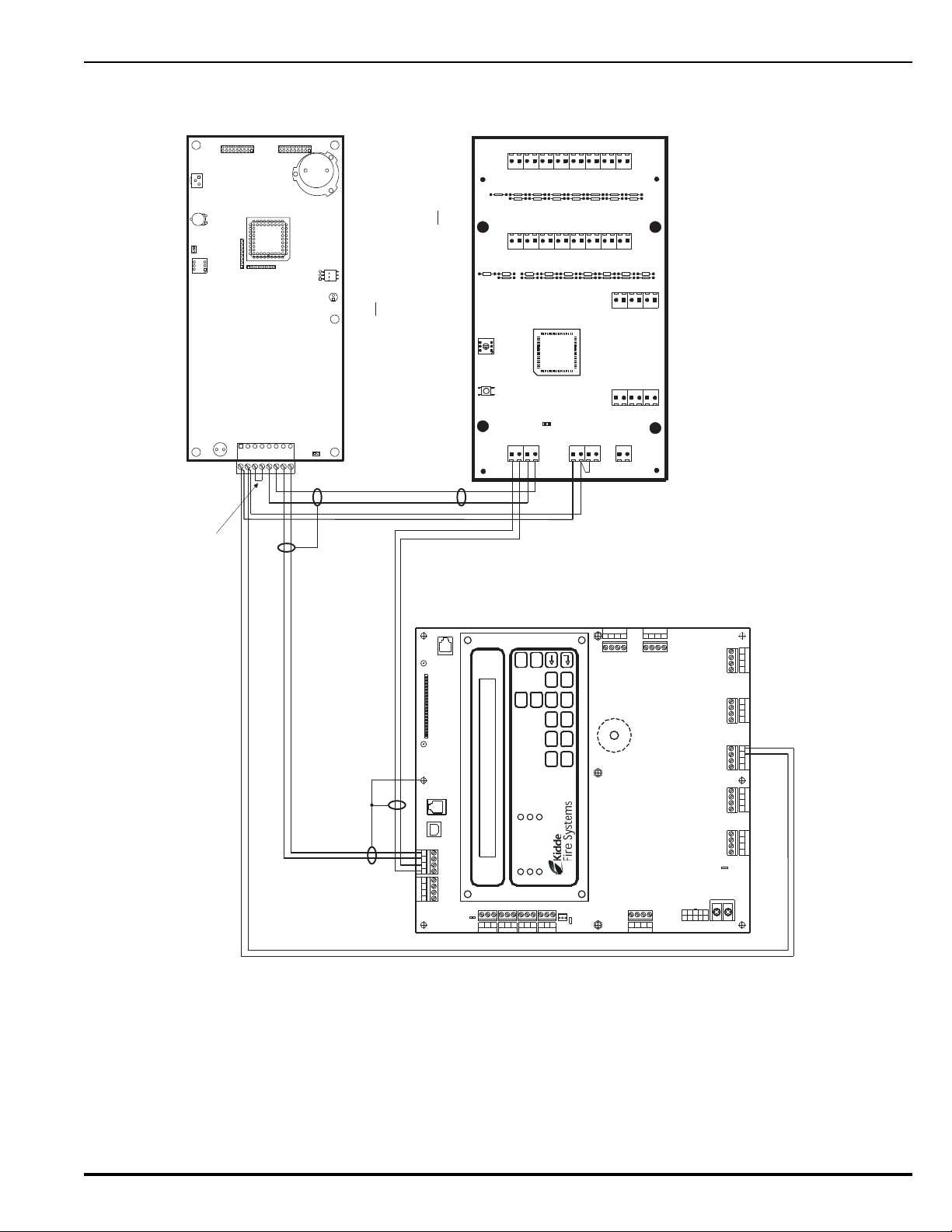
Figure 2-28 shows typical interconnections among the ARIES Control Unit and the peripheral
1234567
8
W2
SW2
DS1
JK1
JK2
SW1
W1
TB1
VR1
VR2
16151413121110
987654321
Lamp Test
Com
Ack
Reset
Silence
Drill
323130292827262524232221201918
17
LK19
LK21
LK18
LK20
LK23
LK22
LK25 LK24
LK27 LK26
LK29 LK28
LK31 LK30
LK32
LK17
LK15LK16
LK13LK14
LK11LK12
LK10
LK8
LK6
LK4
LK2
LK9
LK7
LK5
LK3
LK1
Trouble
Sup.
Sil. Out
Pre Alm
Alarm
Pwr On
A
B
+24 V
Com
PS Flt
W1
Out B
Out A
In B
In A
S2 S1
ATM-L
Remove W2
Install W1
AC POWER
ALARM
PRE-ALARM
SYSTEM TROUBLE
SUPERVISORY
SILENCE
SYSTEM
ACKNOWLEDGE
SYSTEM
RESET
SILENCE
SCROLL
12345
67890
Combo 2
TB6TB7
Combo 1
TB2
Aux 24 VDC
TB11
Release 2
TB12
Release 1
Batt Out
TB3
TroubleRelay 3
Relay 1
Relay 2
1234 1234
1234
1234 1234
120
240
TB13
ACIN
NL
PSU
J12
+
+
--CNCNO
CNCNO
CNCNOCNCNO
SLC
1234
TB5
NAC 1
TB14
1234
NAC 2
RS-232 A
J8
J5
J3
J6
TB15
USB A
USB B
RS 485SLC
TB1
4321
4321
Style 4
S2
J10
Maximum Length: 4,000 Ft.
(Twisted, Shielded, Low-Capacitance Wire)
Refer to Figure 2-29 for maximum-length estimation.
Note: All wiring is power-limited and supervised.
J3
RS-232 B
RDCM Circuit Board
Install Jumper
Connect wires for shields to earth-
ground screw in upper-edge of PCB.
Connect wires for shields together at each
intermediate remote annunciator. Do not connect
wires for shields to the earth-ground screw in
remote enclosures.
Leave shield wires floating at last remote annunciator. Do not
connect wires for shields to the earth-ground screw in last
remote enclosure. Trim shield wires as much as possible.
devices using a dual-channel communications circuit.
Figure 2-28. Dual-Channel RS-485 Wiring to Peripheral Devices
P/N 06-236530-001 2-27 August 2013
Page 70
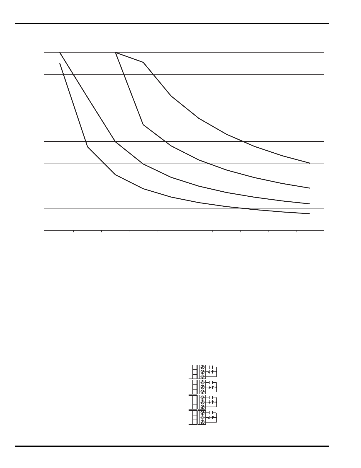
Use Figure 2-29 to estimate the maximum length of wire that can be connected to an Auxiliary-
0
500
1000
1500
2000
2500
3000
3500
4000
0.1 0.2 0.3 0.4 0.5 0.6 0.7 0.8 0.9 1.0
Total Current (A) for RS-485 Peripheral Devices
0.0
#18 AWG
#16 AWG
#14 AWG
#12 AWG
Maximum Distance (Ft.)
NCNO
C
NCNO
C
NCNO
C
NCNO
C
Programmable Relay No. 1
Programmable Relay No. 2
Programmable Relay No. 3
Relay No. 4 (Trouble)
Power Output as a function of RS-485 peripheral-devices current.
Figure 2-29. 24 Vdc-Power Wiring Length vs. Peripheral-Devices Current
Refer to the installation manuals for the remote display module and driver modules for address
selection and additional point-to-point-connection details. The numbers of peripheral devices for
a particular application are specified via the ARIES Programmer’s Guide.
2-14 RELAYS
The ARIES Control Unit has three Form-C, programmable relays and one Form-C, trouble relay
as shown in Figure 2-30. All of these relays have the following contact ratings:
• 1.0 A @ 30 Vdc (resistive)
• 0.5 A @ 30 Vdc (inductive)
August 2013 2-28 P/N 06-236530-001
• 0.5 A @ 120 Vac (inductive)
Figure 2-30. Programmable and Trouble Relays
Page 71
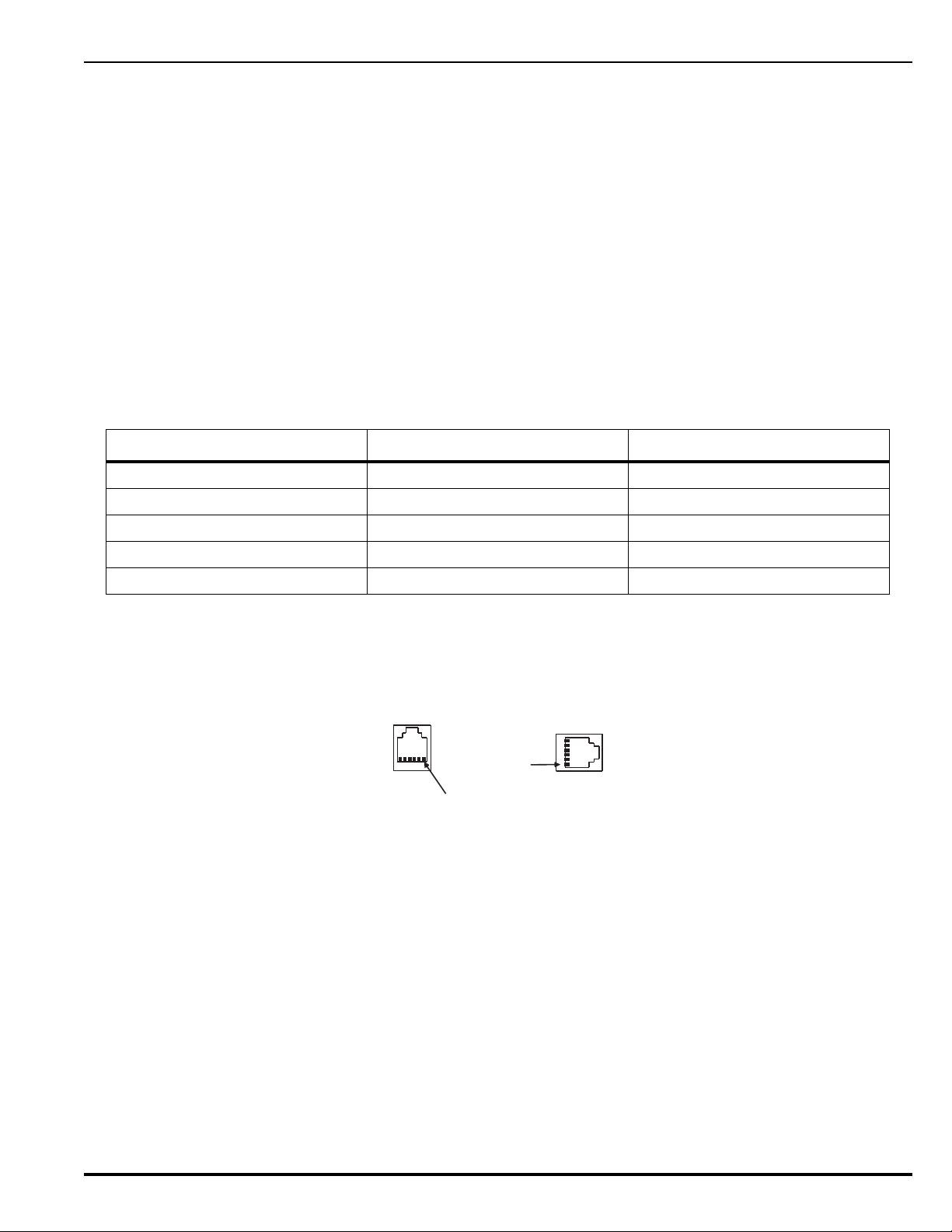
2-15 RS-232 COMMUNICATIONS PORT
Pin 1
J8
Pin 1
J3
The ARIES Control Unit has two RS-232 communications ports (J3/RS232B and J8/RS232A) to
connect to the Intelligent Interface Module (IIM) and various third-party supplementary devices
such as serial printers and graphical monitoring systems.
Note: It is recommended that the RS232B port (J3) be used when only a single RS232 port is
necessary.
• 9600 Baud Rate
•No Parity
• 8 Bit Word Length
•1 Start Bit
•1 Stop Bit
The RS-232 connection to the main printed-circuit board is via an RJ12 socket. The following
signals are communicated via the RJ12 socket’s pins:
Table 2-2. RJ12 Socket Pin Signals
Signal Designation Pin No.
Trans m it Da t a T X 1
Signal Ground Gnd 5
Request to Send RTS 3
Clear to Send CTS 4
Receive Data RX 6
Note: Pin No. 2 is not used.
The RS-232 communications port can be connected to its associated supplementary device with
a standard RS-232 cable of up to 50 feet in length.
Figure 2-31. RS-232 Communications Ports
P/N 06-236530-001 2-29 August 2013
Page 72

2-16 USB COMMUNICATIONS PORT
USB B
J6
USB Device Port
(to PC for
configuration
upload/download)
The ARIES Control Unit has one USB communications port to act as a device for a laptop
computer being used to upload and download a system configuration or to download the
event logs.
The USB port connects to the laptop computer via a standard USB cable.
Note: When using the USB port, the ground fault circuitry is not functional. The USB port is to
be used to download configurations and operating system software only. It is not
intended to be used on a permanent basis. A ground fault will be reported if the USB cable
is connected and no communications activity has occurred for 30 minutes. Do not
connect or disconnect the USB cable while the control unit is powering up on system
startup or initializing after a new configuration upload.
Figure 2-32. USB Communications Port
2-17 NETWORK INTERFACE CARD
The Network Interface Card (NIC) contains the circuitry for data communications between
networked ARIES Control Units. One NIC is required for each networked control unit, and the
control units transmit and receive messages via the RS-485 format.
The NIC supports Class-B, Style-4 or Class-A, Style-7 interconnecting wiring, and acts as a
repeater to boost and regenerate the communications signals. One wire on each
communications channel is an isolated, floating RS-485 transceiver and the other wire is a nonisolated, grounded RS-485 transceiver. This isolates the chassis of the networked control units
to enable ground-fault detection and to eliminate ground loops.
Specifications for the NIC are provided in Table 2-3.
Table 2-3. Network Interface Card Specification
Description Specification
Part Number 74-600000-009
Weight .34 lb/.15 Kg
Input Voltage (From Main PCB) 5.0 VDC
Input Current 300 mA Max @ 5 VDC, 70 mA from 24 VDC Supply
Electrical Field Connections UL Recognized Terminal Blocks for wire size 26 – 12 AWG
Data Ports EIA/TIA-485
Baud Rate 9600 Baud
Temperature Range 0 – 50 Deg C
Humidity Range 0 – 93% RH, non-condensing
August 2013 2-30 P/N 06-236530-001
Page 73
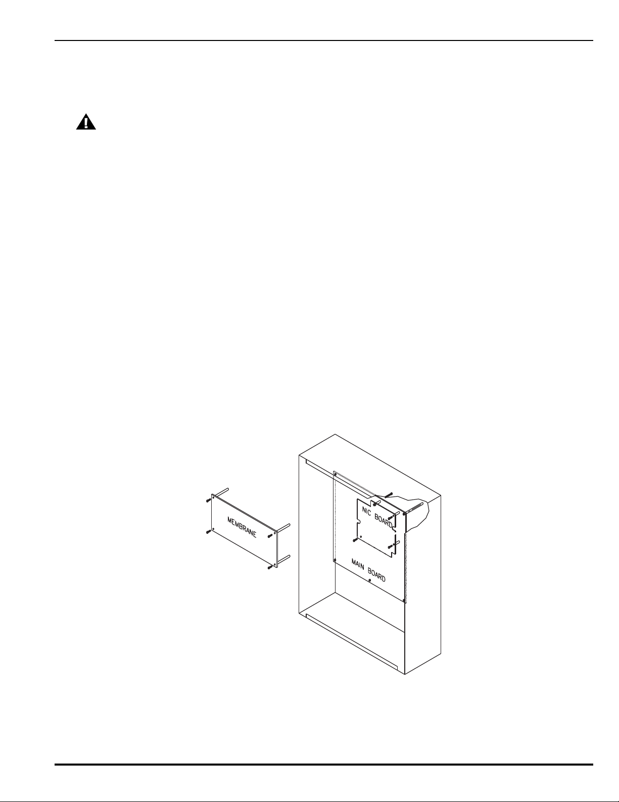
2-17.1 How to Install a NIC
Refer to Figure 2-33 before you install the NIC and perform the following procedure to
install the NIC on the ARIES’s printed-circuit board.
CAUTION
Remove AC and DC power from the control unit before you install a NIC.
1. Slip on a wrist ground strap and connect the clip to the earth ground in the
enclosure. Do not remove the NIC from its shipping carton unless you have
established a common earth-ground potential among yourself, the enclosure, and
the NIC’s shipping carton.
2. Remove the four screws holding the keypad / display to the main PCB. Carefully pull
out the keypad/display from its connectors to the PCB and set aside in a clean, dry
location.
3. Remove the NIC from its shipping carton and locate the three plastic standoffs
included in the installation kit. Insert these standoffs into the three mounting holes
in the PCB as shown in Figure 2-33.
4. Carefully insert the NIC into the 20-pin connector J5 and attach it to the three
plastic standoffs.
5. Secure the upper left-hand corner of the NIC with the long screw and spacer
supplied with the installation kit. The spacer will separate the NIC and the PCB and
the screw will connect to the chassis. Do not over-tighten the screw.
6. Carefully plug the display into its receptacles on the PCB and re-attached with the
four screws. Be sure that the display pins and the PCB receptacles are properly
aligned.
7. Connect network wiring as shown in Paragraph 2-17.2.
Figure 2-33. NIC Installation
2-17.2 Network Wiring
Typical Class-B, Style-4 and Class-A, Style-7 wiring are shown in Figure 2-34 and
Figure 2-35, respectively.
P/N 06-236530-001 2-31 August 2013
Page 74
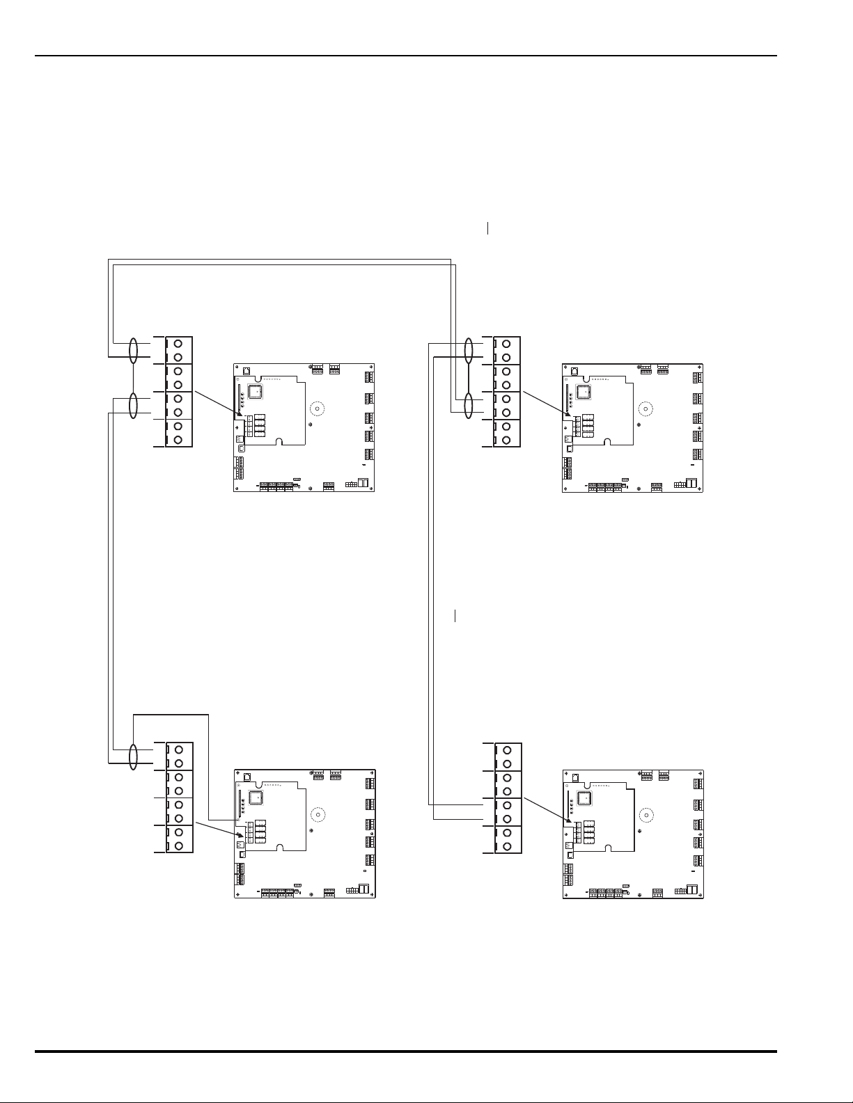
Note: Do not T-Tap the network wiring. Use serial wiring style only. Do not run wiring
Combo2
TB6TB7
Combo1
TB2
Aux24 VDC
TB11
Release2
TB12
Release1
BattOut
TB3
TroubleRel ay 3
Relay 1
Relay 2
1234 1234 1234 1234 1234
120
240
TB13
ACIn
NL
PSU
J12
++--
CNCNO
CNCNO
CNCNOCNCNO
SLC
1234
TB5
NAC1
TB4
1234
NAC2
RS-232
J8
J8
TB15
USBB
RS485SLC
TB1
4321
4321
Style4
S2
J10 J11
B2NA2B1NA1 B2IA2 B1IA1
TB1TB3TB2TB4
K1K3K2K4
J1
DS4 DS2 DS3 DS1
N2 N1 I2 I1
U11
GND
TP1+5TP2I1TP3N1TP4N2TP5I2TP6
B2 N A2
B1 N A1 B2 I A2 B1 I A1
TB1TB3TB2TB4
Combo2
TB6TB7
Combo1
TB2
Aux24 VDC
TB11
Release2
TB12
Release1
BattOut
TB3
TroubleRel ay 3
Relay 1
Relay 2
1234 1234 1234 1234 1234
120
240
TB13
ACIn
NL
PSU
J12
++--
CNCNO
CNCNO
CNCNOCNCNO
SLC
1234
TB5
NAC1
TB4
1234
NAC2
RS-232
J8
J8
TB15
USBB
RS485SLC
TB1
4321
4321
Style4
S2
J10 J11
B2NA2B1NA1 B2IA2 B1IA1
TB1TB3TB2TB4
K1K3K2K4
J1
DS4 DS2 DS3 DS1
N2 N1 I2 I1
U11
GND
TP1+5TP2I1TP3N1TP4N2TP5I2TP6
B2 N A2
B1 N A1 B2 I A2 B1 I A1
TB1TB3TB2TB4
Combo2
TB6TB7
Combo1
TB2
Aux24 VDC
TB11
Release2
TB12
Release1
BattOut
TB3
TroubleRel ay 3
Relay 1
Relay 2
1234 1234 1234 1234 1234
120
240
TB13
ACIn
NL
PSU
J12
++--
CNCNO
CNCNO
CNCNOCNCNO
SLC
1234
TB5
NAC1
TB4
1234
NAC2
RS-232
J8
J8
TB15
USBB
RS485SLC
TB1
4321
4321
Style4
S2
J10 J11
B2NA2B1NA1 B2IA2 B1IA1
TB1TB3TB2TB4
K1K3K2K4
J1
DS4 DS2 DS3 DS1
N2 N1 I2 I1
U11
GND
TP1+5TP2I1TP3N1TP4N2TP5I2TP6
B2 N A2
B1 N A1 B2 I A2 B1 I A1
TB1TB3TB2TB4
Combo2
TB6TB7
Combo1
TB2
Aux24VDC
TB11
Release2
TB12
Release1
BattOut
TB3
TroubleRel ay 3
Relay 1
Relay 2
1234 1234 1234 1234 1234
120
240
TB13
ACIn
NL
PSU
J12
++--
CNCNO
CNCNO
CNCNOCNCNO
SLC
1234
TB5
NAC1
TB4
1234
NAC2
RS-232
J8
J8
TB15
USBB
RS485SLC
TB1
4321
4321
Style4
S2
J10 J11
B2NA2B1NA1 B2IA2 B1IA1
TB1TB3TB2TB4
K1K3K2K4
J1
DS4 DS2 DS3 DS1
N2 N1 I2 I1
U11
GND
TP1+5TP2I1TP3N1TP4N2TP5I2TP6
B2 N A2
B1 N A1 B2 I A2 B1 I A1
TB1TB3TB2TB4
Maximum 4,000 Ft of Wire (#18 AWG or larger) between Control Units
(Twisted, Shielded, Low-Capacitance Wire)
Node 1
Node 2
Node N Node 3
Notes:
1. Do not T-Tap the network wiring. Use
diasy-chained wiring style only.
2. Do not daisy chain wiring back from
Node N to Node 1.
Connect wire for shield to earth-ground screw
in upper-left-hand corner of NIC.
Connect wires for shields together at each
intermediate NIC. Do not connect wires for
shields to the earth-ground screw in
upper-left-hand corner of intermdiate NICs.
Leave shield wire floating at last NIC. Do not connect wire for
shield to the earth-ground screw in upper-left-hand
corner of last NIC. Trim shield wire as much as possible.
Note: All wiring is power-limited and supervised.
back from Node N to Node 1.
THIS PAGE INTENTIONALLY LEFT BLANK.
Figure 2-34. Class-B, Style-4 Network Wiring
August 2013 2-32 P/N 06-236530-001
Page 75
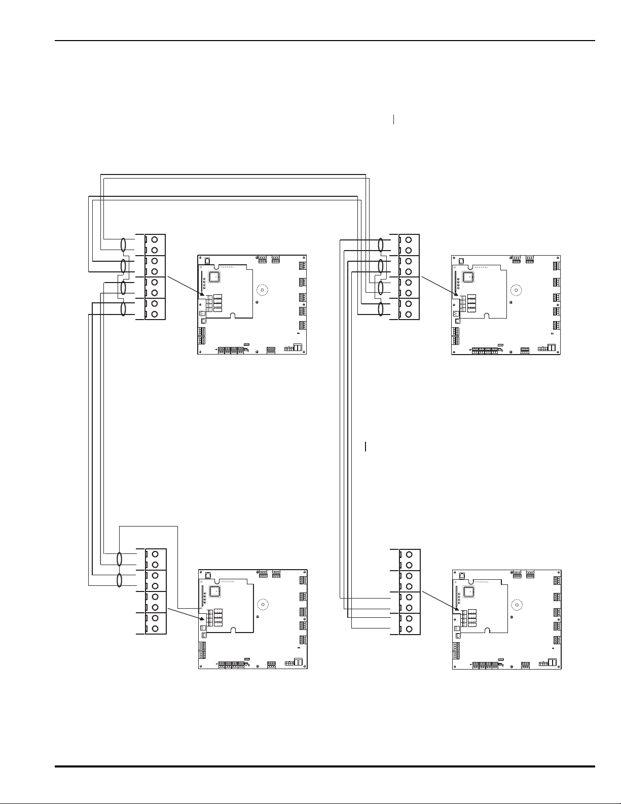
Combo2
TB6TB7
Combo1
TB2
Aux24 VDC
TB11
Release2
TB12
Release1
BattOut
TB3
TroubleRelay 3
Relay 1
Relay 2
1234 1234 1234 12 34 1234
120
240
TB13
ACIn
NL
PSU
J12
++--
CNCNO
CNCNO
CNCNOCNCNO
SLC
1234
TB5
NAC1
TB4
1234
NAC2
RS-232
J8
J8
TB15
USBB
RS485SLC
TB1
4321
4321
Style4
S2
J10
J11
B2NA2B1NA1 B2IA2 B1IA1
TB1TB3TB2TB4
K1K3K2K4
J1
DS4 DS2 DS3 DS1
N2 N1 I2 I1
U11
GND
TP1+5TP2I1TP3N1TP4N2TP5I2TP6
B2 N A2
B1 N A1 B2 I A2 B1 I A1
TB1TB3TB2TB4
Combo2
TB6TB7
Combo1
TB2
Aux24 VDC
TB11
Release2
TB12
Release1
BattOut
TB3
TroubleRelay 3
Relay 1
Relay 2
1234 1234 1234 12 34 1234
120
240
TB13
ACIn
NL
PSU
J12
++--
CNCNO
CNCNO
CNCNOCNCNO
SLC
1234
TB5
NAC1
TB4
1234
NAC2
RS-232
J8
J8
TB15
USBB
RS485SLC
TB1
4321
4321
Style4
S2
J10
J11
B2NA2B1NA1 B2IA2 B1IA1
TB1TB3TB2TB4
K1K3K2K4
J1
DS4 DS2 DS3 DS1
N2 N1 I2 I1
U11
GND
TP1+5TP2I1TP3N1TP4N2TP5I2TP6
B2 N A2
B1 N A1 B2 I A2 B1 I A1
TB1TB3TB2TB4
Combo2
TB6TB7
Combo1
TB2
Aux24 VDC
TB11
Release2
TB12
Release1
BattOut
TB3
TroubleRelay 3
Relay 1
Relay 2
1234 1234 1234 12 34 1234
120
240
TB13
ACIn
NL
PSU
J12
++--
CNCNO
CNCNO
CNCNOCNCNO
SLC
1234
TB5
NAC1
TB4
1234
NAC2
RS-232
J8
J8
TB15
USBB
RS485SLC
TB1
4321
4321
Style4
S2
J10
J11
B2NA2B1NA1 B2IA2 B1IA1
TB1TB3TB2TB4
K1K3K2K4
J1
DS4 DS2 DS3 DS1
N2 N1 I2 I1
U11
GND
TP1+5TP2I1TP3N1TP4N2TP5I2TP6
B2 N A2
B1 N A1 B2 I A2 B1 I A1
TB1TB3TB2TB4
Combo2
TB6TB7
Combo1
TB2
Aux24 VDC
TB11
Release2
TB12
Release1
BattOut
TB3
TroubleRelay 3
Relay 1
Relay 2
1234 1234 1234 12 34 1234
120
240
TB13
ACIn
NL
PSU
J12
++--
CNCNO
CNCNO
CNCNOCNCNO
SLC
1234
TB5
NAC1
TB4
1234
NAC2
RS-232
J8
J8
TB15
USBB
RS485SLC
TB1
4321
4321
Style4
S2
J10
J11
B2NA2B1NA1 B2IA2 B1IA1
TB1TB3TB2TB4
K1K3K2K4
J1
DS4 DS2 DS3 DS1
N2 N1 I2 I1
U11
GND
TP1+5TP2I1TP3N1TP4N2TP5I2TP6
B2 N A2
B1 N A1 B2 I A2 B1 I A1
TB1TB3TB2TB4
Maximum 4,000 Ft of Wire (#18 AWG or larger) per channel between Control Units
(Twisted, Shielded, Low-Capacitance Wire)
Channel 1Channel 2
Node 1
Node 2
Node N
Node 3
Notes:
1. Do not T-Tap the network wiring. Use
diasy-chained wiring style only.
2. Do not daisy chain wiring back from
Node N to Node 1.
Connect wires for both shields to earth-ground
screw in upper-left-hand corner of NIC.
Connect wires for shields together for each channel
at every intermediate NIC. Do not connect wires for
shields to the earth-ground screw in the upper-
left-hand corner of intermdiate NICs.
Leave shield wires floating at last NIC. Do not connect wires for
both shields to the earth-ground screw in upper-left-hand
corner of last NIC. Trim shield wires as much as possible.
Note: All wiring is power-limited and supervised.
Figure 2-35. Class-A, Style-7 Network Wiring
P/N 06-236530-001 2-33 August 2013
Page 76

2-18 FIBER-OPTIC CONVERTER CARD
The Fiber-Optic Converter Card allows networked ARIES Control Units to be interconnected
using fiber-optic medium. Use one OCC to terminate each end of a fiber-optic communicationschannel(s) segment. The ARIES networking structure supports a mixture of fiber-optic and
twisted-wire interconnections among networked control units.
Specifications for the Fiber-Optic Converter Card are provided in Table 2-4.
Table 2-4. Fiber-Optic Converter Card Specification
Description Specification
Part Number 74-600000-006
Weight 3.3 lb/1.5 Kg
Finish Dark Blue (Color 35044 of Fed Std 595A)
Input Voltage 24 VDC Nominal, 18 VDC Min, 28 VDC Max
NOTE: Must be connected to a power supply listed for fire-protective signaling
use only.
Input Current 200 mA Max
Electrical Connections UL Recognized Terminal Blocks for wire size 26 – 12 AWG
Fiber-Optic Connections Type ‘ST’
Data Ports EIA/TIA-485
Baud Rate 9600 Baud
Optical Link Distance 5280 ft (With no more than 4 dB/km cable attenuation)
Temperature Range 0 – 50 Deg C
Humidity Range 0 – 93% RH, non-condensing
The OCC Cabinet should be located as required in the same room as its parent Control Unit for
convenient wiring connections (24 VDC and RS485 communications).
Typical Class-B, Style-4 and Class-A, Style-7 interconnections using a mixture of media are
shown in Figures 2-36 through 2-39.
Figure 2-36 shows a typical single-channel system using 62.5/125 m duplex fiber-optic media.
August 2013 2-34 P/N 06-236530-001
Page 77
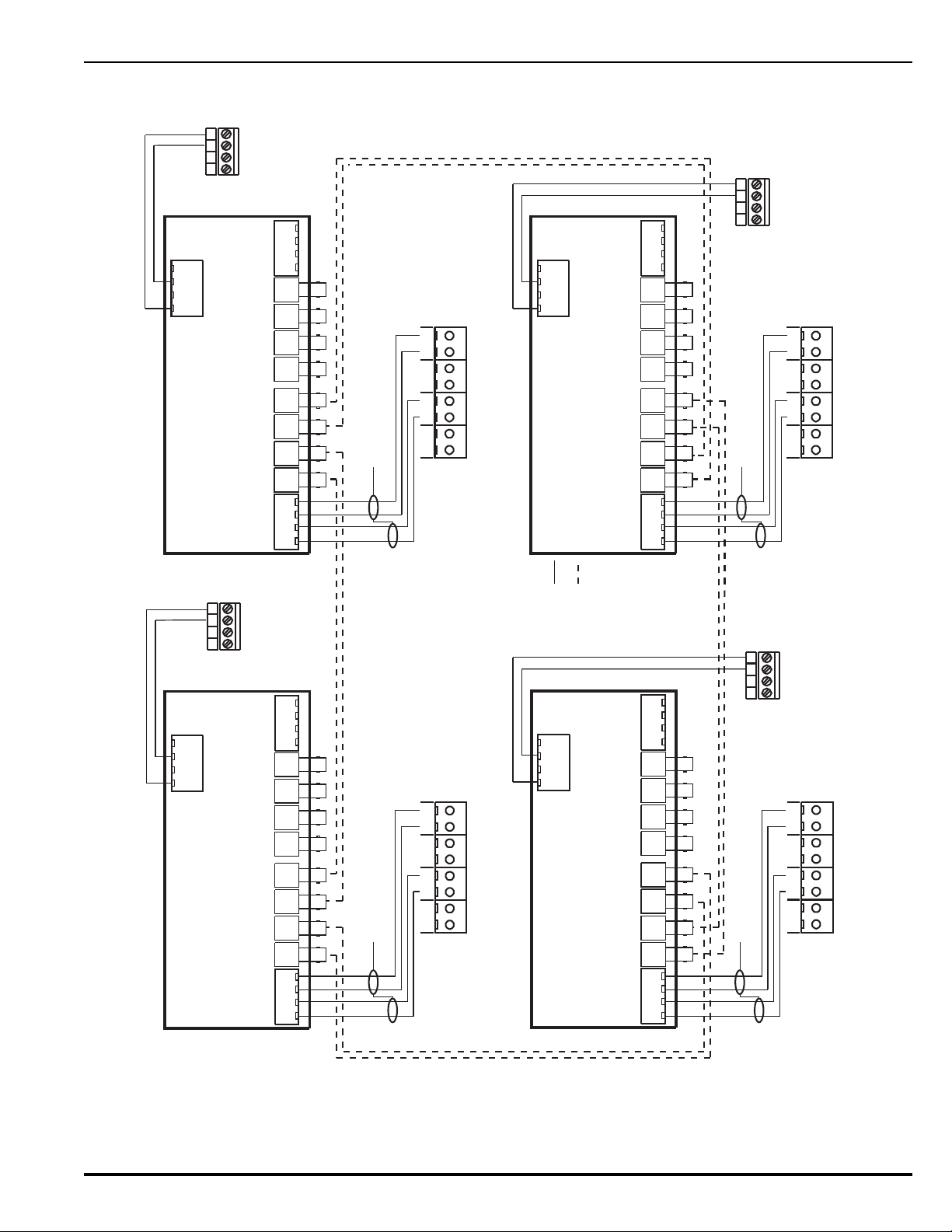
Node 1
Node 2
Node N
Node 3
B2 N A2
B1 N A1 B2 I A2 B1 I A1
TB1TB3TB2TB4
TB1
RxN TxN RxI
Q1 D1 Q2 D3
TxI RxN TxN RxI TxI
Q3 D5 Q4 D7
B1N B1IA1N A1I
TB2
B2N B2IA2N A2I
24V
+ -+ -
B2 N A2
B1 N A1 B2 I A2 B1 I A1
TB1TB3TB2TB4
TB1
RxN TxN RxI
Q1 D1 Q2 D3
TxI RxN TxN RxI TxI
Q3 D5 Q4 D7
B1N B1IA1N A1I
TB2
B2N B2IA2N A2I
24V
+ -+ -
B2 N A2
B1 N A1 B2 I A2 B1 I A1
TB1TB3TB2TB4
TB1
RxN TxN RxI
Q1 D1 Q2 D3
TxI RxN TxN RxI TxI
Q3 D5 Q4 D7
B1N B1IA1N A1I
TB2
B2N B2IA2N A2I
24V
+ -+ -
B2 N A2
B1 N A1 B2 I A2 B1 I A1
TB1TB3TB2TB4
TB1
RxN TxN RxI
Q1 D1 Q2 D3
TxI RxN TxN RxI TxI
Q3 D5 Q4 D7
B1N B1IA1N A1I
TB2
B2N B2IA2N A2I
24V
+ -+ -
Channel 1
Channel 2
Channel 1 Channel 2
Channel 1
Channel 2
Channel 1
Channel 2
4321
TB2
Aux. Power Terminals
Control Unit PCB
(Non-Resettable)
4321
TB2
Aux. Power Terminals
Control Unit PCB
(Non-Resettable)
4321
TB2
Aux. Power Terminals
Control Unit PCB
(Non-Resettable)
4321
TB2
Aux. Power Terminals
Control Unit PCB
(Non-Resettable)
NIC Terminals
(Node 1)
NIC Terminals
(Node 2)
NIC Terminals
(Node 3)
NIC Terminals
(Node N)
OCC
(Node 1)
OCC
(Node 2)
OCC
(Node 3)
OCC
(Node N)
Connect wires for shields to earth-ground
screw in upper-left-hand corner of NIC.
Connect wires for shields to earth-ground
screw in upper-left-hand corner of NIC.
Max. 1 Mile of Fiber (62.5/125 um duplex) between Control Units
Installation Notes:
1. Do not T-Tap the network fiber. Use daisy-chained interconnections.
2. Daisy chain fiber back from Node N to Node 1.
3. Use twisted, shielded wire for NIC - OCC interconnections.
Key
Ch1 Twisted,
Shielded Wire Pair
Ch1 62.5/125um
Duplex Fiber Optics
(ST Connectors)
Connect wires for shields to earth-ground
screw in upper-left-hand corner of NIC.
Connect wires for shields to earth-ground
screw in upper-left-hand corner of NIC.
Note: All wiring is power-limited and supervised.
Figure 2-36. Typical Single-Channel System using 62.5/125 m Duplex Fiber-Optic Media
P/N 06-236530-001 2-35 August 2013
Page 78
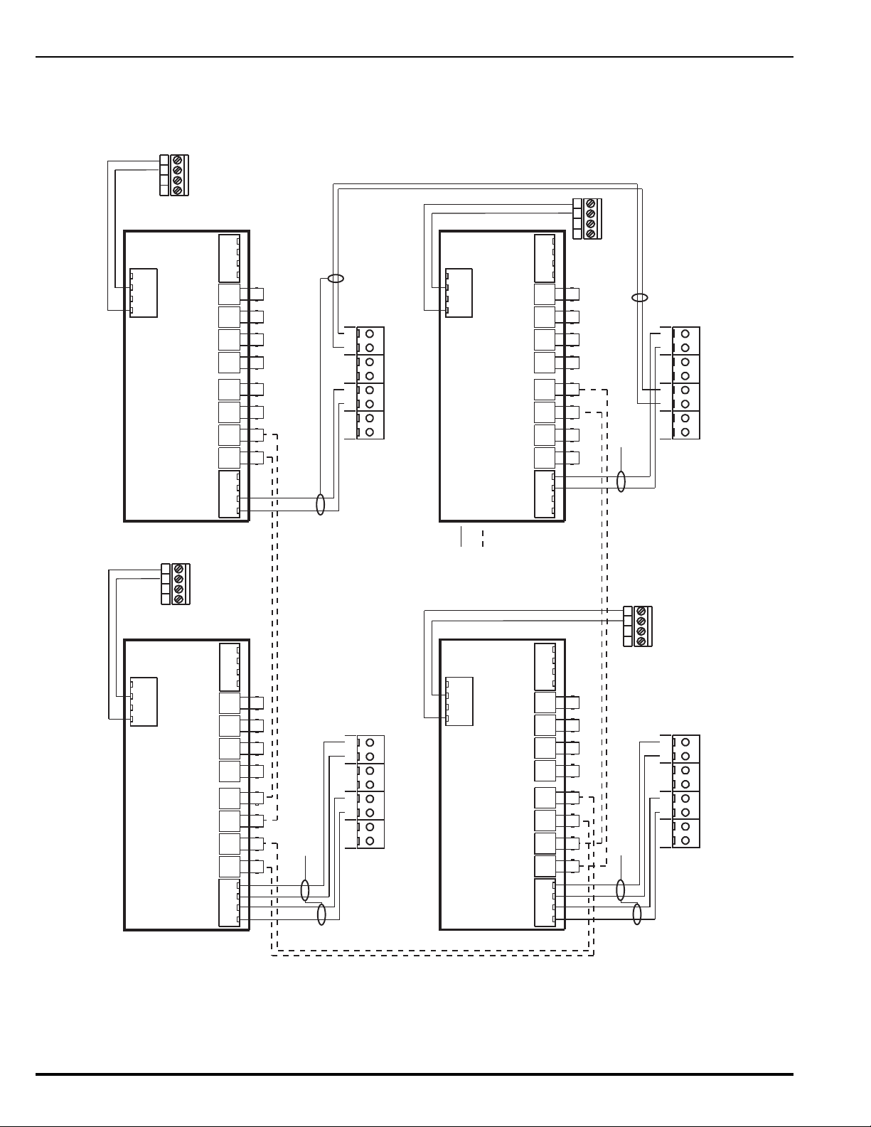
Figure 2-37 shows the same single-channel system, but using a combination of 62.5/125 m
Node 1
Node 2
Node N
Node 3
B2 N A2
B1 N A1 B2 I A2 B1 I A1
TB1TB3TB2TB4
TB1
RxN TxN RxI
Q1 D1 Q2 D3
TxI RxN TxN RxI TxI
Q3 D5 Q4 D7
B1N B1IA1N A1I
TB2
B2N B2IA2N A2I
24V
+ -+ -
B2 N A2
B1 N A1 B2 I A2 B1 I A1
TB1TB3TB2TB4
TB1
RxN TxN RxI
Q1 D1 Q2 D3
TxI RxN TxN RxI TxI
Q3 D5 Q4 D7
B1N B1IA1N A1I
TB2
B2N B2IA2N A2I
24V
+ -+ -
B2 N A2
B1 N A1 B2 I A2 B1 I A1
TB1TB3TB2TB4
TB1
RxN TxN RxI
Q1 D1 Q2 D3
TxI RxN TxN RxI TxI
Q3 D5 Q4 D7
B1N B1IA1N A1I
TB2
B2N B2IA2N A2I
24V
+ -+ -
B2 N A2
B1 N A1 B2 I A2 B1 I A1
TB1TB3TB2TB4
TB1
RxN TxN RxI
Q1 D1 Q2 D3
TxI RxN TxN RxI TxI
Q3 D5 Q4 D7
B1N B1IA1N A1I
TB2
B2N B2IA2N A2I
24V
+ -+ -
Channel 1
Channel 2
Channel 1 Channel 2
Channel 1
Channel 2
Channel 1
Channel 2
4321
TB2
Aux. Power Terminals
Control Unit PCB
(Non-Resettable)
4321
TB2
Aux. Power Terminals
Control Unit PCB
(Non-Resettable)
4321
TB2
Aux. Power Terminals
Control Unit PCB
(Non-Resettable)
4321
TB2
Aux. Power Terminals
Control Unit PCB
(Non-Resettable)
NIC Terminals
(Node 1)
NIC Terminals
(Node 2)
NIC Terminals
(Node 3)
NIC Terminals
(Node N)
OCC
(Node 1)
OCC
(Node 2)
OCC
(Node 3)
OCC
(Node N)
Connect wire for shield to
ground screw in upper-left
-hand corner of NIC.
Connect wires for shields to earth-ground
screw in upper-left-hand corner of NIC.
Max. 1 Mile of Fiber (62.5/125 um duplex) between Control Units
Installation Notes:
1. Do not T-Tap the network fiber. Use daisy-chained interconnections.
2. Daisy chain fiber back from Node N to Node 1.
3. Use twisted, shielded wire for NIC - OCC and NIC - NIC interconnections.
Key
Ch1 Twisted,
Shielded Wire Pair
Ch1 62.5/125um
Duplex Fiber Optics
(ST Connectors)
Connect wires for shields to earth-ground
screw in upper-left-hand corner of NIC.
Connect wires for shields to earth-ground
screw in upper-left-hand corner of NIC.
Note: All wiring is power-limited and supervised.
duplex fiber-optic media and twisted, shielded, low-capacitance wiring.
Figure 2-37. Typical Single-Channel System using Combination Twisted, Shielded and Fiber-Optic Media
August 2013 2-36 P/N 06-236530-001
Page 79
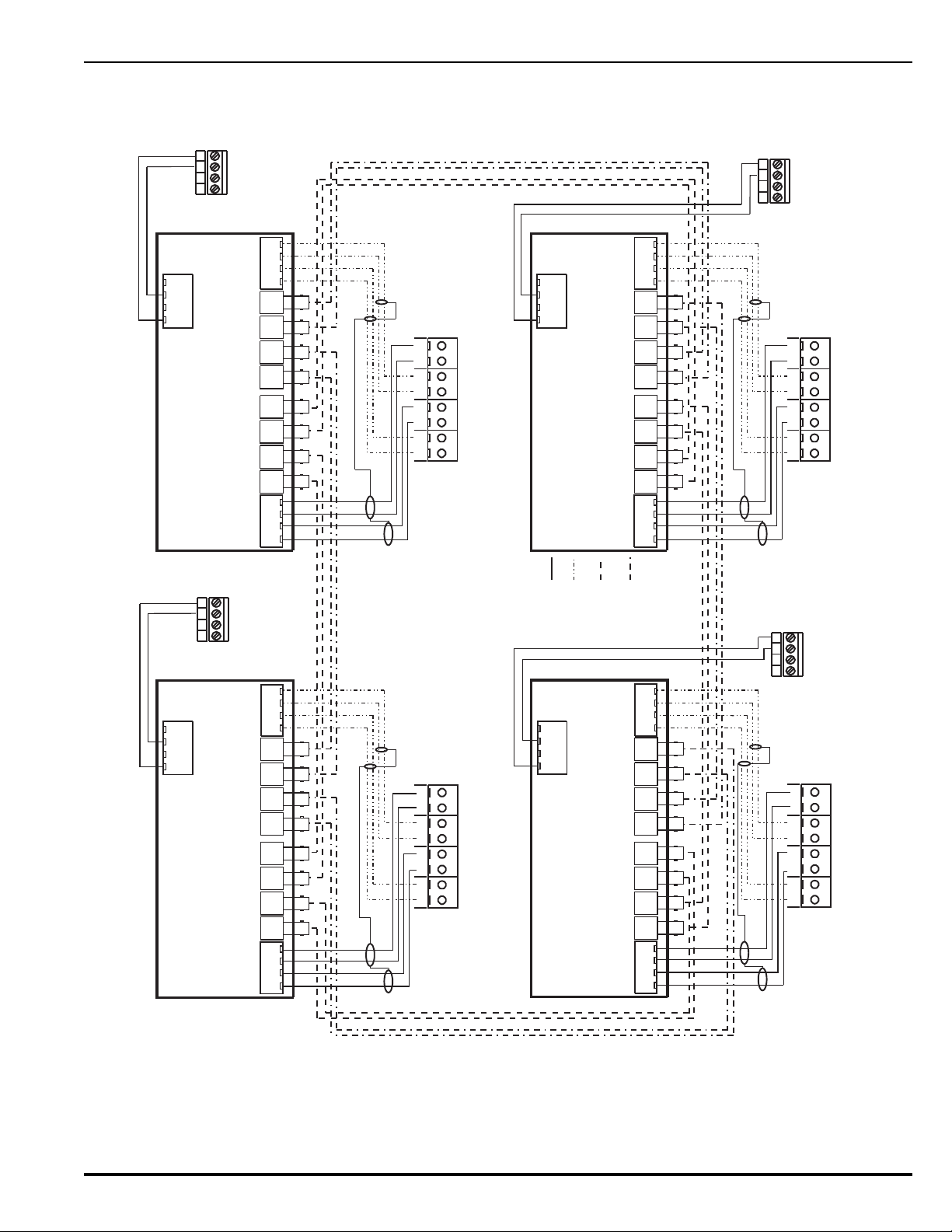
Figure 2-38 shows a typical dual-channel system using 62.5/125 m duplex fiber-optic media.
Node 1
Node 2
Node N
Node 3
B2 N A2
B1 N A1 B2 I A2 B1 I A1
TB1TB3TB2TB4
TB1
RxN TxN RxI
Q1 D1 Q2 D3
TxI RxN TxN RxI TxI
Q3 D5 Q4 D7
B1N B1IA1N A1I
TB2
B2N B2IA2N A2I
24V
+ -+ -
B2 N A2
B1 N A1 B2 I A2 B1 I A1
TB1TB3TB2TB4
TB1
RxN TxN RxI
Q1 D1 Q2 D3
TxI RxN TxN RxI TxI
Q3 D5 Q4 D7
B1N B1IA1N A1I
TB2
B2N B2IA2N A2I
24V
+ -+ -
B2 N A2
B1 N A1 B2 I A2 B1 I A1
TB1TB3TB2TB4
TB1
RxN TxN RxI
Q1 D1 Q2 D3
TxI RxN TxN RxI TxI
Q3 D5 Q4 D7
B1N B1IA1N A1I
TB2
B2N B2IA2N A2I
24V
+ -+ -
B2 N A2
B1 N A1 B2 I A2 B1 I A1
TB1TB3TB2TB4
TB1
RxN TxN RxI
Q1 D1 Q2 D3
TxI RxN TxN RxI TxI
Q3 D5 Q4 D7
B1N B1IA1N A1I
TB2
B2N B2IA2N A2I
24V
+ -+ -
Channel 1
Channel 2
Channel 1 Channel 2
Channel 1
Channel 2
Channel 1
Channel 2
4321
TB2
Aux. Power Terminals
Control Unit PCB
(Non-Resettable)
4321
TB2
Aux. Power Terminals
Control Unit PCB
(Non-Resettable)
4321
TB2
Aux. Power Terminals
Control Unit PCB
(Non-Resettable)
4321
TB2
Aux. Power Terminals
Control Unit PCB
(Non-Resettable)
NIC Terminals
(Node 1)
NIC Terminals
(Node 2)
NIC Terminals
(Node 3)
NIC Terminals
(Node N)
OCC
(Node 1)
OCC
(Node 2)
OCC
(Node 3)
OCC
(Node N)
Connect wires for shields to ground screw
in upper-left-hand corner of NIC.
Connect wires for shields
to ground screw in upper-
left-hand corner of NIC
Installation Notes:
1. Do not T-Tap the network fiber. Use daisy-chained interconnections.
2. Daisy chain fiber back from Node N to Node 1.
3. Use twisted, shielded wire for NIC - OCC interconnections.
Connect wires for shields
to ground screw in upper-
left-hand corner of NIC
Connect wires for shields
to ground screw in upper-
left-hand corner of NIC.
Max. 1 Mile of Fiber (62.5/125 um duplex)
between Control Units
Key
Ch1 Twisted,
Shielded Wire Pair
Ch2 Twisted,
Shielded Wire Pair
Ch1 62.5/125um
Duplex Fiber Optics
(ST Connectors)
Ch2 62.5/125um
Duplex Fiber Optics
(ST Connectors)
Note: All wiring is power-limited and supervised.
Figure 2-38. Typical Dual-Channel System using 62.5/125 m Duplex Fiber Optic Media
P/N 06-236530-001 2-37 August 2013
Page 80
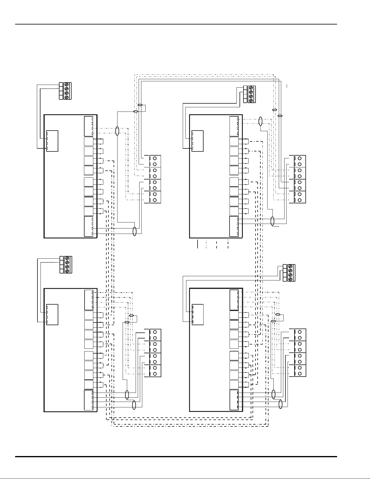
Figure 2-39 shows the same dual-channel system, but using a combination of 62.5/125 m
Node 1
Node 2
Node N
Node 3
B2 N A2
B1 N A1 B2 I A2 B1 I A1
TB1TB3TB2TB4
TB1
RxN TxN RxI
Q1 D1 Q2 D3
TxI RxN TxN RxI TxI
Q3 D5 Q4 D7
B1N B1IA1N A1I
TB2
B2N B2IA2N A2I
24V
+ -+ -
B2 N A2
B1 N A1 B2 I A2 B1 I A1
TB1TB3TB2TB4
TB1
RxN TxN RxI
Q1 D1 Q2 D3
TxI RxN TxN RxI TxI
Q3 D5 Q4 D7
B1N B1IA1N A1I
TB2
B2N B2IA2N A2I
24V
+ -+ -
B2 N A2
B1 N A1 B2 I A2 B1 I A1
TB1TB3TB2TB4
TB1
RxN TxN RxI
Q1 D1 Q2 D3
TxI RxN TxN RxI TxI
Q3 D5 Q4 D7
B1N B1IA1N A1I
TB2
B2N B2IA2N A2I
24V
+ -+ -
B2 N A2
B1 N A1 B2 I A2 B1 I A1
TB1TB3TB2TB4
TB1
RxN TxN RxI
Q1 D1 Q2 D3
TxI RxN TxN RxI TxI
Q3 D5 Q4 D7
B1N B1IA1N A1I
TB2
B2N B2IA2N A2I
24V
+ -+ -
Channel 1
Channel 2
Channel 1 Channel 2
Channel 1
Channel 2
Channel 1
Channel 2
4321
TB2
Aux. Power Terminals
Control Unit PCB
(Non-Resettable)
4321
TB2
Aux. Power Terminals
Control Unit PCB
(Non-Resettable)
4321
TB2
Aux. Power Terminals
Control Unit PCB
(Non-Resettable)
4321
TB2
Aux. Power Terminals
Control Unit PCB
(Non-Resettable)
NIC Terminals
(Node 1)
NIC Terminals
(Node 2)
NIC Terminals
(Node 3)
NIC Terminals
(Node N)
OCC
(Node 1)
OCC
(Node 2)
OCC
(Node 3)
OCC
(Node N)
Connect wires for shields
to ground screw in upper-
left-hand corner of NIC
Installation Notes:
1. Do not T-Tap the network fiber. Use daisy-chained interconnections.
2. Daisy chain fiber back from Node N to Node 1.
3. Use twisted, shielded wire for NIC - OCC and NIC - NIC interconnections.
Connect wires for shields
to ground screw in upper-
left-hand corner of NIC
Connect wires for shields
to ground screw in upper-
left-hand corner of NIC.
Max. 1 Mile of Fiber (62.5/125 um duplex)
between Control Units
Leave shield wire floating at Node 3. Do not connect wire for
shield to the earth-ground screw in upper-left-hand
corner of last NIC. Trim shield wire as much as possible.
Key
Ch1 Twisted,
Shielded Wire Pair
Ch2 Twisted,
Shielded Wire Pair
Ch1 62.5/125um
Duplex Fiber Optics
(ST Connectors)
Ch2 62.5/125um
Duplex Fiber Optics
(ST Connectors)
Connect wires for shields to ground screw
in upper-left-hand corner of NIC.
Note: All wiring is power-limited and supervised.
duplex fiber-optic media and twisted, shielded, low-capacitance wiring.
Use ST connectors to attach the fiber-optic media to the OCCs.
Figure 2-39. Typical Dual-Channel System using Combination Twisted, Shielded and Fiber Optic Media
August 2013 2-38 P/N 06-236530-001
Page 81
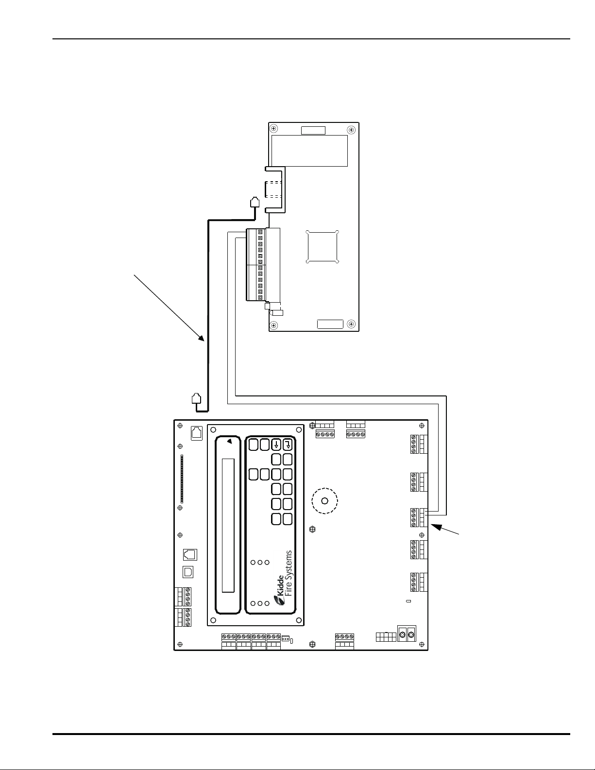
2-19 INTELLIGENT INTERFACE MODULE
Combo 2
TB6TB7
Combo 1
TB2
Aux 24 VDC
TB11
Release 2
TB12
Release 1
Batt Out
TB3
TroubleRelay 3Relay 1 Relay 2
1234 12 34
1234
1234 1234
120
240
TB13
AC IN
NL
PSU
J12
+
+
--
CNCNO
CNCNO
CNCNOCNCNO
1234
TB5
NAC 1
TB14
1234
NAC 2
RS-232 A
J8
J5
TB15
USB B
RS 485SLC
TB1
4321
4321
Style 4
S2
J10
J3
RS-232 B
TB4 TB8 TB9 TB1 0
CCM PC TEL
123456
7
89101112
RS-232 Communications Cable
Connect from IIM Port labeled "CCM"
to control-unit port J8 (RS-232 A).
Configure Port J8 for operation with IIM.
Refer to Paragraph 3-2.5.2.4.5
Control-Unit PCB
IIM PCB
AC POWER
ALARM
PRE-ALARM
SYSTEM TROUBLE
SUPERVISORY
SILENCE
SYSTEM
ACKNOWLEDGE
SYSTEM
RESET
SILENCE
SCROLL
1 2 3 4 5
6 7 8 9 0
Auxiliary Power Terminals
(Non re-settable)
The interconnection of the Intelligent Interface Module to the ARIES Control Unit is shown in
Figure 2-40. Refer to the ORION-XT Installation, Operation and Maintenance Manual
(Publication 77.100) for additional details.
Figure 2-40. Interconnection of IIM
P/N 06-236530-001 2-39 August 2013
Page 82

THIS PAGE INTENTIONALLY LEFT BLANK.
August 2013 2-40 P/N 06-236530-001
Page 83

CHAPTER 3
SYSTEM OPERATIONS
3-1 ARIES SYSTEM OPERATIONS OVERVIEW
This chapter addresses operation of individual and networked ARIES™ Fire Alarm/Suppression
Control Unit.
The control unit uses field-programmable software. Refer to the Configuration Software User’s
Guide in P/N 76-600000-008 for instructions on how to program the ARIES System.
3-2 SYSTEM OPERATION
This section instructs the end-user how to operate an ARIES Control Unit, including how to
distinguish the different operating states, how to use the operator keys, and what the status
indicating LEDs mean.
Refer also to the Operating Instructions, P/N 06-236406-001, that are packaged with the control
unit.
3-2.1 Operating States
The control unit has two operating modes: Normal and Off-Normal. Normal Mode is
characterized by the absence of any initiating signals from either automatic detectors or
monitor modules, and by the absence of trouble conditions. Off-Normal Mode is triggered
by system events or operator interrogation via the keypad. Off-Normal Mode operating
states are listed in Table 3-1.
Table 3-1. Off-Normal Mode Operating States
Operating State Triggering Event(s)
Access-Via-Menu A operator uses the keypad to isolate initiating devices and/or outputs, list
configuration settings and the application program, adjust configuration settings, or
manually initiate testing procedures.
Trouble A report of a problem that could prevent the ARIES System from proper operation.
Typical trouble signals include: Lack of response from a configured device on the
signaling line circuit; Internal fault reported by a SmartOne detector; Loss of
monitoring integrity of the installation conductors; Power-supply fault; and/or Loss of
primary AC power.
Alarm An automatic spot-type smoke or heat detector or a high-sensitivity smoke detector
senses a fire signature that is greater than the detector's programmable alarm
threshold, or when a monitor module programmed as a manual-alarm, manualrelease, waterflow or general-alarm point activates.
Pre-Alarm An automatic spot-type smoke, heat detector or a high-sensitivity smoke detector
senses a fire signature that is greater than a programmable, lower-level warning
threshold but less than the detector's programmable alarm threshold.
Supervisory A monitor module detects a condition such as gate-valve closure, low air pressure or
water level, or pump failure that could impair the operation of a building's sprinkler
system. It also enters this state when an operator isolates any initiating or control
devices or control-unit-based output circuits. This mode is primarily event-driven.
P/N 06-236530-001 3-1 August 2013
Page 84
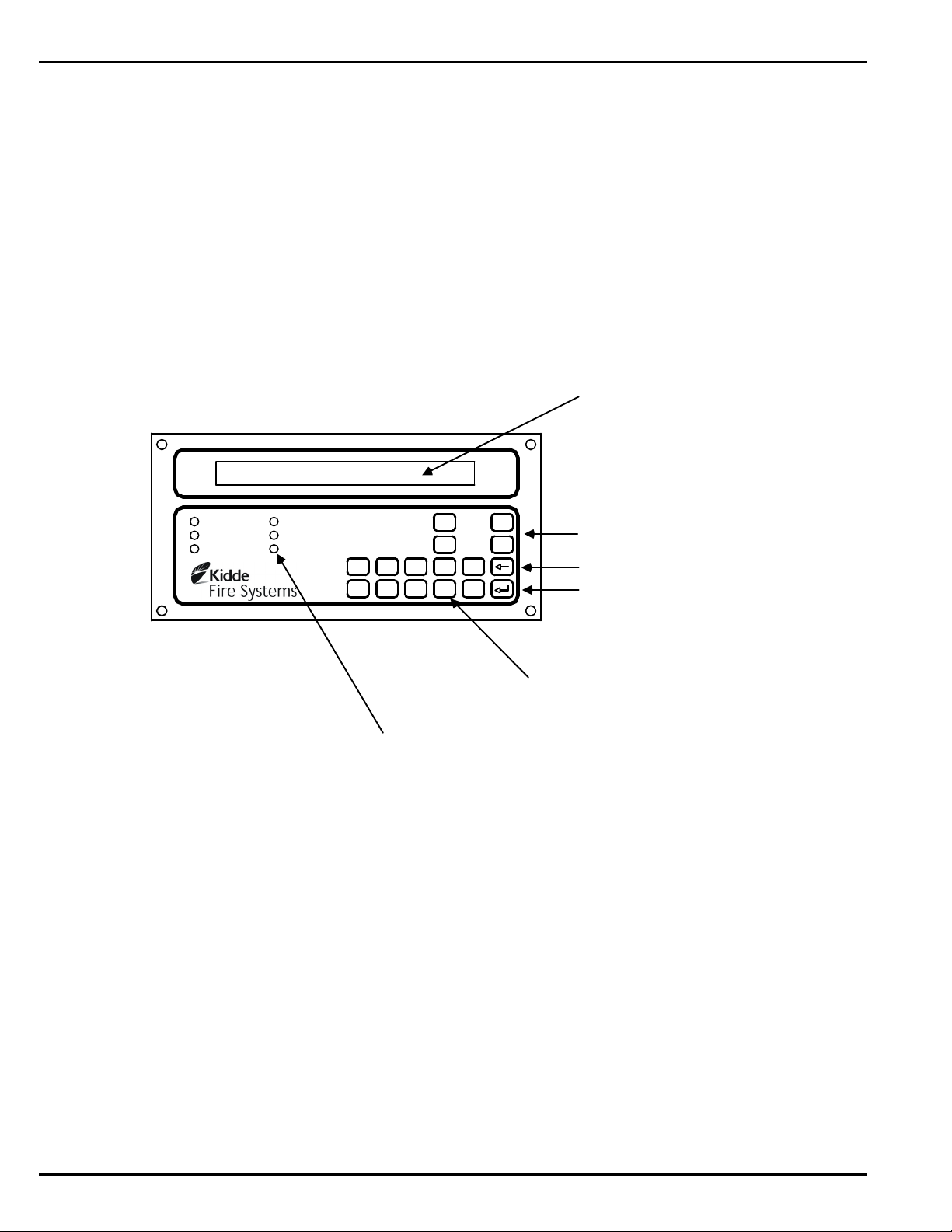
3-2.2 Outputs Activation
AC POWER
ALARM
PRE-ALARM
SYSTEM TROUBLE
SUPERVISORY
SILENCE
SYSTEM
ACKNOWLEDGE
SYSTEM
RESET
SILENCE
SCROLL
12345
67890
80 Character
Liquid Crystal Display
with LED Back Lighting
(2 Lines X 40 Characters)
12-key numeric / BACKSPACE /
ENTER keypad
ENTER Key
BACKSPACE Key
Operator Control Keys
System Status LEDs
The ARIES System operation is control by events. Control-unit-based or signalingline-circuit-based outputs are activated by user-specified operating instructions
contained in the system’s event output control (EOC) program. The EOC program is
triggered by any event that transitions the system from the Normal Mode to an
event-driven, Off-Normal operating state.
Note: All alarm events must be annunciated by public-mode notification.
3-2.3 Operator Keys
Operator keys for the ARIES System are located on the display inside the control unit.
The control unit door must be open to access the operator keys.
Figure 3-1 shows the location of the operator keys and status indicating LEDs on the
display. Table 3-2 lists the names and functions of the operator keys on the display.
Figure 3-1. Display Panel
August 2013 3-2 P/N 06-236530-001
Page 85

Table 3-2. Operator Control Keys and Functions
BUTTON FUNCTION
<ACKNOWLEDGE> The <ACKNOWLEDGE> Key allows the operator to signal the ARIES System Control
Unit that a new event currently being displayed is understood. The control unit's
audible notification appliance will silence and all flashing Pre-Alarm, Alarm,
Supervisory, or Trouble LEDs will light steadily when all active events have been
acknowledged.
<SILENCE> Pressing the <SILENCE> Key after all current alarm events have been
acknowledged shuts off any active, silenceable control-unit-based or signaling-linecircuit-based outputs, such as notification-appliance circuits or control modules.
Note: There is a 10-second buffer period during which subsequent presses of the
<SILENCE> Key are intentionally ignored. A subsequent key press will only be
acted upon after at least 10 seconds have elapsed since the previous key press.
<RESET> The <RESET> Key restores the ARIES System to Normal Mode after all alarm
system events have been acknowledged and have ceased reporting alarm
conditions.
<SCROLL> The <SCROLL> Key allows the operator to view all currently-active events by time
of occurrence. Also used to navigate through the menu options.
NUMERIC KEYPAD (0-9) Used to enter passwords, navigate through the menu options, and specify numeric
operating data.
<BACKSPACE> Used to exit the menu system and to delete incorrect entries.
<ENTER> Used as the <ENTER> Key for the menu system.
P/N 06-236530-001 3-3 August 2013
Page 86

3-2.4 Status Indicating LEDs
Table 3-3 lists the names and functions of the system status LEDs on the display.
Table 3-3. System Status LEDs and Functions
LED COLOR FUNCTION
Power On Green A steady LED indicates primary AC power is on at acceptable levels.
An unlit LED indicates unacceptable AC power levels or AC power is
disconnected.
Alarm Red A flashing LED indicates one or more unacknowledged alarm events, or that a
previously-acknowledged non-latching alarm device has issued an alarm-off
report.
A steady LED indicates all alarm events and alarm-off reports have been
acknowledged.
The LED turns off when the control unit is reset if all current alarm events and
alarm-off messages have been acknowledged and none of the alarm-initiating
devices are reporting alarms.
Pre-Alarm Yellow A flashing LED indicates unacknowledged pre-alarm events.
A steady LED indicates all current pre-alarm events have been acknowledged.
The LED turns off when the control unit receives pre-alarm-off messages from
all alarm-initiating devices that had reported a pre-alarm.
Trouble Yellow A flashing LED indicates unacknowledged trouble events.
A steady LED indicates all trouble events have been acknowledged.
The LED turns off when the control unit receives trouble-off messages from all
SLC or IIM devices or control-unit monitoring circuitry that had reported
trouble conditions.
Supervisory Yellow A flashing LED indicates one or more unacknowledged supervisory events.
A steady LED indicates all supervisory events have been acknowledged.
The LED turns off when the control unit receives supervisory-off messages
from all initiating devices that had reported supervisory conditions.
Silence Yellow A steady LED indicates the Silence Key has been pressed after all current
alarm events have been acknowledged.
The LED turns off when 1) the control unit is reset, or 2) the Silence key is
pressed to toggle on any previously-silenced NACs and SLC-based modules.
The Silence key will repeatedly toggle the NACs and SLC-based modules off
and on and the Silence LED will track the activation state of the NACs and
modules until the control unit is reset.
August 2013 3-4 P/N 06-236530-001
Page 87

3-2.5 Operating Instructions
SYSTEM STATUS NORMAL 02:15 PM 07/02/04
North Communications Center
System Normal
Message
Site-Specific
Custom Message
The following paragraphs give general operating instructions for a stand-alone system.
3-2.5.1 NORMAL OPERATION
There are no active events such as alarms or troubles during Normal Mode
operation. The control unit continuously monitors all initiating devices and
supervised circuits for any changes of state.
The LCD display shows the “System Status Normal” message, the time and date,
and an optional user-defined custom message as shown in Figure 3-2.
Figure 3-2. Normal Operation Display
3-2.5.2 MENU OPERATION
The ARIES has a built-in menu structure. This menu structure has been
implemented to aid users with system operating functions. The following
paragraphs describe the menu structure, how to access the menu, menu
functions, and how to exit the menu.
An operator can use menu operation to:
• Isolate initiating devices and/or outputs
• List configuration settings and the application program
• Adjust configuration settings
• Initiate manual testing procedures
An operator cannot use menu operation if:
• He is attempting to access the main menu via an RDCM while another
operator already has access to the system
• Another operator already has access to the system through the
configuration program’s terminal-emulation mode (Refer to the ARIES
Programming Guide for information on terminal-emulation mode.)
Any of the following events cancel Menu operation:
• An alarm signal
• An operator presses the <Backspace> Key at the main menu.
• A period of 60 seconds elapses from the last pressed key.
P/N 06-236530-001 3-5 August 2013
Page 88

3-2.5.2.1 Menu Functions
1: ISOLATE 2: LIST
3: SET 4: TEST
Note: The control unit continuously monitors all initiating devices and
outputs for any state change while in menu operation.
The main menu functions are shown in Figure 3-3.
Most functions will require additional data to be entered to implement the
function, such as a device address or desired alarm threshold.
Figure 3-3. Main Menu Functions
Table 3-4 lists and provides a brief description of typical functions that can
be performed using the ARIES System’s menus. Figure 3-4 contains the
ARIES main menu functions and top-level displays.
Table 3-4. Main Menu Functions and Descriptions
Menu Function Description
Isolation Device and
Circuit Isolation
List Listing of
Events and
System
Settings
Set Change
Operating
Parameters
Test Confirming
Proper
Operation
The isolation commands prevent the ARIES Control Unit from acting upon
signals from initiating devices or from issuing activation commands to controlunit-based and SLC-based outputs. The initiating devices and outputs remain
operational, but are disconnected from the control unit in the sense that events
reported by isolated initiating devices are ignored by the control unit and
commands to activate are ignored by isolated outputs and control modules.
The list commands are used to view the set of isolated initiating devices and
control-unit-based and SLC-based outputs. These commands are also used to
display configuration settings for automatic initiating devices, to display the list
of devices on the SLC and on the Intelligent Interface Module, and to view
lower-level events that are not displayed due to the occurrence of higher-level
events.
The set commands allow the installer to change the sensitivity settings for
Smart-One automatic initiating devices, to address and register initiating and
control devices, to activate a set of networked control units or to define global
operating parameters such as Global Acknowledgement of trouble and
supervisory events. These commands are also used to trigger automatic
configuration routines such as AutoLearn and AutoSetup.
The test commands enable service personnel to test the SmartOne initiating
devices for the ability to transmit alarm signals. You can also perform alarmsimulation tests for the system's application program and can command on
control modules connected to the SLC.
August 2013 3-6 P/N 06-236530-001
Page 89
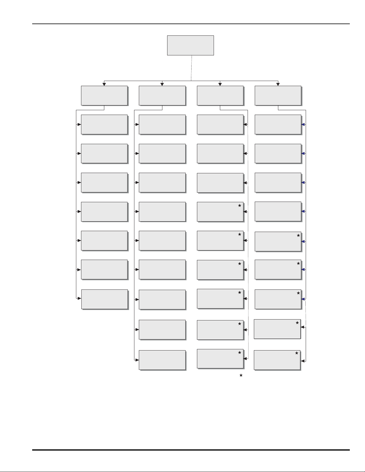
Please Enter Password
1:ISOLATE
2. Outputs
3. Control Modules
7. HSDs
2:LIST
1. Isolated Devices
2. Event Logs
3. Detector Levels
4. Active Events
5. EOC Program
6. SLC Assignments
3:SET
1. Time / Date
2. Port Control
4:TEST
1. SLC Devices
2. Fire Drill
7. Voltages
8. HSD Assignments
1. SLC Devices
9. More Options
3. Battery Test
5. Walk Test
6. Alarm Sim Test
7. Ouput Test
3. SLC Devices (Installer)
3. Battery (Owner)
Level-2 (Installer) Password required.
4. Programming
5. Globals
6. Network
7. Control Modules
8. SLC Resistance
9. More Options
8. HSDS
9. Battery
4. Lamp Test
4. Global Isolate
6.Isolation Macro 2
5. Isolation Macro 1
P/N 06-236530-001 3-7 August 2013
Figure 3-4. ARIES Menu Functions and Top-Level Displays
Page 90

THIS PAGE INTENTIONALLY LEFT BLANK.
August 2013 3-8 P/N 06-236530-001
Page 91
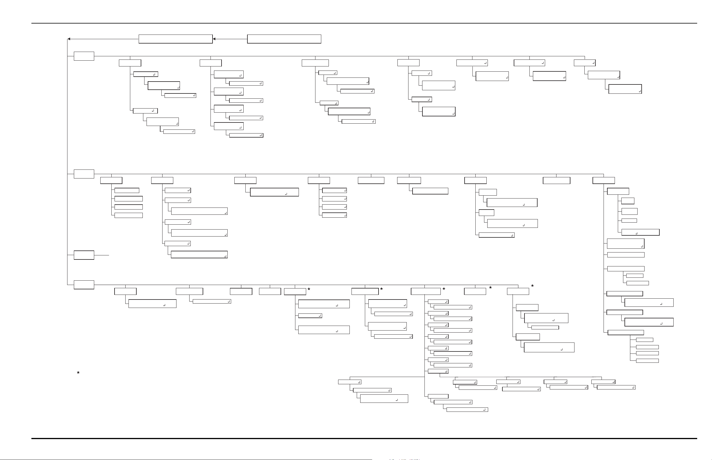
System Operations
1. Isolate
1. SLC Devices
Devices from*__to___
2. Outputs
1. NACs
SG*toSG
2. Release Circuits
AR*toAR
3. Combo Circuits
Combo * to Combo
1: Isolate 2: De-Isolate *
1. Isolate 2: De-Isolate *
1. Isolate 2: De-Isolate *
3. Control Modules
1. ATM
Isolate / De-Isolate ATMs
Enter the ATMNumber (01 - 16) *
2. List
1. Isolated Devices
1. SLC Devices
2. Outputs
2. Event Logs 3. Detector Levels 4. Active Events
2. Alarm Events
3. Supervisories
4. Troubles
5. EOC Program 6. SLC Assignments 7. Voltages
SLC Device Line Voltage
SLC Devices From *__to___ (1-255)
9. More Options
3. Set
Enter Password
Addr Type Owner Location
3. Control Modules
1. Pre-Alarm Events
1: Isolate 2: De-Isolate *
4. Test
See Figure 3-6
Enter Begin and End Dates for Range
Date Range *_-_ _-_ _ to _ _-_ _-_ _ (MMDDYY)
1. All System Events
5. Isolate Macro 1
Isolate SLC Devices
4. Relays
Relay * to Relay
1. Isolate 2: De-Isolate *
4. Global Isolate
1. Inputs *
2. Outputs *
1. Isolate 2: De-Isolate *
1. Isolate 2: De-Isolate *
Global Isolation of Outputs
Global Isolation of Inputs
2. Range of Events
SLC TestResults Listing
SLC Devices From *_ _ to _ _ _ (1 - 255)
3. SLC TestResults
SLC TestResults Listing
SLC Devices From *_ _ to___ (1-255)
4. Walk-TestResults
3. Battery Charge
4. Lamp Test1. SLC Devices
Start Device Test
SLC Devices From*__to___ (1-255)
3. Battery Test
5. Walk Test
2. Stop Walk Test
6. Alarm Sim Test
7. Outputs Test
1: NAC 1 *
2. Fire Drill
Activate - (1) Deactivate - (0)
8. SLC Resistance 9. More Options
6. Isolate Macro 2
SLC Devices from *__to___ (1-255)
SLC Detector Levels
Detector 9 Volt Reading
SLC Devices From *__to___ (1-255)
4. Network Settings
Press "0" Key
1. Start WalkTest
SLC Devices From *__to___ (1-255)
3. Silent Walk Test
SLC Devices From *__to___ (1-255)
1. SLC Alarm Sim
Enter SLC Address*__ (1-255)
Activate - (1) Deactivate - (0)
2: NAC 2 *
Activate - (1) Deactivate - (0)
3: Combo 1 *
Activate - (1) Deactivate - (0)
4: Combo 2 *
Activate - (1) Deactivate - (0)
5: Release 1 *
Activate - (1) Deactivate - (0)
6: Release 2 *
Activate - (1) Deactivate - (0)
7: Relays *
1: Relay 1 *
Activate - (1) Deactivate - (0)
2: Relay 2 *
Activate - (1) Deactivate - (0)
3: Relay 3 *
Activate - (1) Deactivate - (0)
4: Trouble Relay *
Activate - (1) Deactivate - (0)
1. Onboard Circuits
1. NACs
2. Release
3. Combos
4. Enter Relay Number:
RY *
8. HSD Assignments
8: SLC Outputs *
SLC Outputs Test
SLC Devices From *__to___ (1-255)
Activate - (1) Deactivate - (0)
Level-2 (Installer) Password required.
Legend
1. Find Dup Address
2. SLC Comm Value
2. Control Modules
List Control / Display Modules
1. ATM 2. RDCM :*
Activate - (1) Deactivate - (2)
7. HSDs
Enter SLC Address * _ _ (1 - 255)
SLC Double Address Detector LED Utility
Press Backspace to Exit
SLC Devices From * _ _ To___ (1-255)
SLC Communication Value
1. SLC Inputs *
2. SLC Outputs *
Devices from*__to___
1: Isolate 2: De-Isolate *
Isolate SLC Devices
Devices from *__to___
1: Isolate 2: De-Isolate *
Isolate SLC Devices
Devices from *__to___
1: Isolate 2: De-Isolate *
Isolate SLC Devices
1. Isolate 2: De-Isolate *
2. RDCM
Isolate / De-Isolate ATMs
Enter the ATMNumber (01 - 15) *
1. Isolate 2: De-Isolate *
1. ATM
1. Isolate 2: De-Isolate *
Isolation Macro 1
1. Isolate 2: De-Isolate *
Isolation Macro 2
Devices from*__to___
Isolate SLC Devices
HSD*__to___
Isolate HSDs
1. Isolate 2: De-Isolate *
Isolate HSDs
4. HSDs
1. Line Voltage
2. 9 Volts
1. This Node
2. Network Nodes
2. HSD Alarm Sim
Enter HSD Address * _ _ (1 - 127)
Activate - (1) Deactivate - (2)
9: RRM Group *
Activate - (1) Deactivate - (0)
Enter RRM Group Number * (1-4)
7. List Versions
1. This Node
2. Network Nodes
1. This Node
2. Network Nodes
1. Main CPU
2. SLC Version
1. This Node
2. Network Nodes
3. Main CPU Boot
4. SLC Version
5. RRM PSU Status
RRM Extended Status
RRM Devices From *__to___ (1-255)
RRM Extended Status
RRM Devices From*__to___ (1-255)
6. RRM Memory Status
3. General Alarm
P/N 06-236530-001 3-9 (Page 3-10 blank) August 2013
Figure 3-5. Menu Functions
Page 92

Page 93
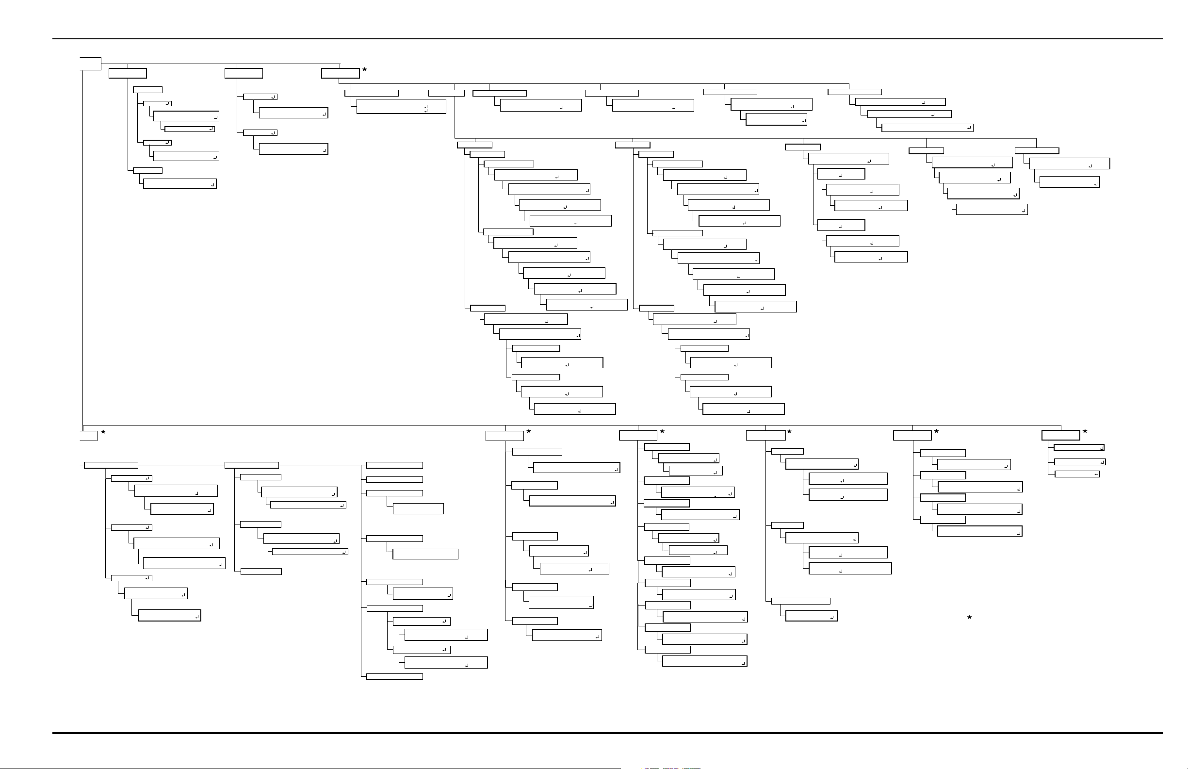
System Operations
Set
2. Configuration
1. Time / Date
1. Set Time
1. AM / PM
2. Military
System Time (AM / PM 1 - 12 Hrs)
Enter the Time *_:_ _ (HH:MM)
Set Time (Mil 1 - 24 Hrs))
Enter the Time *_:_ _ (HH:MM)
2. Port Control
1. RS232 A *
3. SLC Devices
1. Device Addr Change
Set Loop Device Address
Present Loop Device Address*_ _
Set Target LoopAddress *_ _
1. Ionization
Set Detector Sensitivity
SLC Devices From * _ _ to _ _ _
Set Detector Sensitivity
1: Open Area 2: In Duct 3: DH-2000 *
Set Detector Sensitivity
Pre-Alarm Level *._ (0.5 - 1.4) %/Ft.
Set Detector Sensitivity
Alarm Level *._ (0.5 - 1.5) %/Ft.
3 Thermal
Set Detector Sensitivity
SLC Devices From *_ _ to _ _ _
Set Detector Sensitivity
1: 50 Ft. *
Set Detector Sensitivity
Pre-Alarm Level *__ (80 - 154)
Set Detector Sensitivity
Alarm Level *__ (135 - 155)
4 Alarmline
Set AAM Configuration
SLC Devices From *_ _ to _ _ _
Set AAM Configuration
Switch Setting 1 to 16 *_
Set AAM Configuration
Pre-Alarm 1: ON 2: OFF *
Set AAM Configuration
Alarm 1: Normal 2: Overheat *
2. Set Date
Set Date
Enter the Date *_-__-__ (MM-DD-YY)
3. Registration
Device Registration
SLC Devices From *_ _ to _ _ _
4. De-Registration
5. Blink Control
Device De-Registration
SLC Devices From *_ _ to _ _ _
Program Device Blink Control
SLC Devices From *_ _ to _ _ _
1. Alarm
1. Fixed Settings
2. Day/Night Settings
2. Photoelectric
Set Blink Control
1: Blink Off 2: Blink On
1: PRINTER 2: IIM
3: ICM 0: NOT USED *
2. RS232 B *
1: PRINTER 2: IIM
3: ICM 0: NOT USED *
1: AM 2: PM *
(1 - 255)
(1 - 255)
(1 - 255)
Set Detector Sensitivity
SLC Devices From * _ _ to _ _ _
(1 - 255)
Set Detector Sensitivity
1: Open Area 2: In Duct 3: DH-2000 *
(1 - 255)
(1 - 255)
(1 - 255)
(1 - 255)
(1 - 255)
Set Detector Sensitivity
2: 70 Ft. *
Set Detector Sensitivity
Pre-Alarm Level *__ (80 - 144)
Set Detector Sensitivity
Alarm Level *__ (135 - 145)
Set Detector Sensitivity
1: Open Area 2: In-Duct / DH-2000 *
2. Supervisory
Set Detector Sensitivity
SLC Devices From * _ _ to _ _ _
(1 - 255)
1. Fixed Settings
Set Detector Sensitivity
Alarm Level *._ (0.5 - 1.5) %/Ft.
2. Day / Night Settings
Set Detector Sensitivity
Day Alarm Level *._ (0.5 - 1.5) %/Ft.
Set Detector Sensitivity
Pre-Alarm Level *._ (0.5 - 1.4) %/Ft.
Set Detector Sensitivity
Day Alarm Level *._ (0.5 - 1.5) %/Ft.
Set Detector Sensitivity
Night Alarm Level *._ (0.5 - 1.4) %/Ft.
Set Detector Sensitivity
Night Alarm Level *._ (0.5 - 1.4) %/Ft.
Set Detector Sensitivity
SLC Devices From * _ _ to _ _ _
Set Detector Sensitivity
1: Open Area 2: In Duct 3: DH-2000 *
Set Detector Sensitivity
Pre-Alarm Level *._ (0.2 - 3.4) %/Ft.
Set Detector Sensitivity
Alarm Level *._ (0.5 - 3.5) %/Ft.
1. Alarm
1. Fixed Settings
2. Day/Night Settings
(1 - 255)
Set Detector Sensitivity
SLC Devices From * _ _ to _ _ _
(1 - 255)
Set Detector Sensitivity
1: Open Area 2: In Duct 3: DH-2000 *
Set Detector Sensitivity
1: Open Area 2: In-Duct / DH-2000 *
2. Supervisory
Set Detector Sensitivity
SLC Devices From * _ _ to _ _ _
(1 - 255)
1. Fixed Settings
Set Detector Sensitivity
Alarm Level *._ (0.5 - 3.5) %/Ft.
2. Day / Night Settings
Set Detector Sensitivity
Day Alarm Level *._ (0.5 - 3.5) %/Ft.
Set Detector Sensitivity
Pre-Alarm Level *._ (0.2 - 3.4) %/Ft.
Set Detector Sensitivity
Day Alarm Level
*._ (0.5 - 3.5) %/Ft.
Set Detector Sensitivity
Night Alarm Level
*._ (0.5 - 3.4) %/Ft.
Set Detector Sensitivity
Night Alarm Level
*._ (0.5 - 3.4) %/Ft.
amming
1. Day / Night
1. Set Detectors
Set Day Period (Now 08:00)
Day Period Start *_:__ (24 hour clock)
2. Set Periods
Set Day / Night / Weekend Mode
SLC Devices From *_ _ to _ _ _
3. Activate
2. Passwords
1. Owner's
2. Installer's
Change Installer Password
Enter New Password *_______
3. AutoLearn
5. Globals
1. Global Acknowledge
6. Network
7. Control Modules
1. Register
Register Control / Display Module
1: ATM 2: RDCM *
1: Enter the ATM Number to Register
ATM: *_
2: Enter the RDCM Number to Register
RDCM: *_
2. De-Register
De-Register Control / Display Module
1: ATM 2: RDCM *
1. Enter the ATM Number to De-Register
ATM: *_
2. Enter the RDCM Number to De-Register
RDCM: *_
3. Reset ATM / RDCM
Reset Control Module
1: Reset 2: Exit *
Set Night Period (Now 18:00)
Night Period Start *_:__ (24 hour clock)
2. Alarm Verification
Nighttime Settings at Night
1. Activate 2. De-Activate *
Assign Alarm Verification
Verification Period *_ (060 - 180 Seconds)
3. PAS
Set Delay Period in Seconds
*_ (Max. 180 Seconds)
Level-2 (Installer) Password required.
Legend
(1 - 255)
Nighttime Settings on Weekend
1. Activate 2. De-Activate *
Re-Enter New Password *________
Change Owner Password
Enter New Password *_______
Re-Enter New Password *________
Positive Alarm Sequence
Activate - (1) Deactivate - (0) *
4. Central Station
Central Station Operation
8. HSDs
Day / Night / Weekend Mode
1. Activate 2. De-Activate *
9. Battery
1. Battery Disp Enable
5. Alarm Verification
7. Clear Events
Assign Alarm Verification
6. Positive Alarm Sequence
Assign Positive Alarm Sequence
1: Enable 2: Disable
4. AutoSetup
9. Resynch. Network
8. Clear Tests
1. Clear SLC Tests *
2. Clear Walk Tests *
Clearing SLC Test Results
SLC Devices From *_ _ to _ _ _
(1 - 255)
Clearing Walk Test Results
SLC Devices From *_ _ to _ _ _
(1 - 255)
Event Log Clear
1: Clear Events 2: Exit *
1. Style
2. Node Number
Change Style
1: Ch1 2: Ch2 3. Both
Change Style
1: Enable 2: Disable
Change Node Number
1: Range (1 to 32) 2: Standalone
3. Group
Change Group
1: Group (1 to 32) 2: Not Grouped
4. Add/Remove Nodes
Add/Remove Network Nodes
1: Add 2: Remove
Add/Remove Network Nodes
Nodes: *__ to __
5. Reset Event
Change Network Reset
1: Enable 2: Disable
6. Silence Event
Change Network Silence
1: Enable 2: Disable
7. Log Events
Log All Events or Only Log Group Events
1: Log All Events 2: Log Group Events
8. Time Synch Period
Change Time Synch
Period: 0 (Off) or 600-32767 Sec ____
9. Isolate
Isolate/De-isolate Node
1: Isolate 2: De-isolate
1. Register IIM
Register IIM On Port
1: RS232A 2: RS232B
2. De-register IIM
Disable IIM On Port
1: Confirm 2: Cancel
3. Register HSDs
HSD Registration
HSD Devices From ___ to ___ (1 - 127)
4. De-register HSDs
HSD De-registration
HSD Devices From ___ to ___ (1 - 127)
5 Remote Release
Set RRM Configuration
SLC Devices From *_ _ to _ _ _
(1 - 255)
Set RRM Configuration
1: Solenoid
2: Actuator *
3. Get MFG Code
5. Global Alarm Ack
Global Acknowledge of Alarms
Activate - (1) Deactivate - (2) *
3. Disable Battery
2. Battery Disp Disable
5. Replace Device
Present SLC Device Address *_ _
1: Keep Current Settings 2: Set Default
(0 - 255)
SLC Device Addr to Change *_ _
(1 - 255)
*._ (0.5 - 3.4) %/Ft.
Activate - (1) Deactivate - (2) *
1: Enable 2: Disable
Global Acknowledge of Trouble/Supv
Acknowledge - (1)
Deactivate - (0) *
P/N 06-236530-001 3-11 (Page 3-12 blank) August 2013
Figure 3-6. Menu Functions Cont.
Page 94

Page 95

3-2.5.2.2 Isolate Menu Functions
The Isolate functions prevent the ARIES Control Unit from acting upon
signals from initiating devices or from issuing activation commands to
control unit-based and SLC-based outputs. The initiating devices and
outputs remain operational, but are disconnected from the control unit in
the sense that events reported by isolated initiating devices are ignored by
the control unit and commands to activate are ignored by isolated outputs
and control modules.
A Supervisory signal will occur after each Isolation command is executed,
and will remain in effect until all Isolation commands are subsequently
cancelled by their corresponding De-Isolation commands.
For Top-Level Isolate Menu Functions, refer to Figure 3-4. For the
complete Isolate-Menu tree, refer to Figure 3-5.
The following paragraphs list the Isolate Menu functions.
3-2.5.2.2.1 How to Isolate SLC Devices
Purpose: To prevent initiating and trouble signals from selected
SmartOne automatic detectors and monitor modules from being
processed and acted upon by the ARIES Control Unit. Also to prevent
selected SmartOne control and relay modules from carrying out
activation instructions issued by the ARIES Control Unit.
Note: An SLC device can only be isolated if it is not in either a trouble
or alarm condition.
Step Action Result
1 Press 0 Key Initiate menu access
2 Enter Password; Press “Enter” Key Gain access to menus
3 Press 1 Key Enter Isolate-Menu branch
4 Press 1 Key Select "SLC Devices" option
5 Press 1 Key for SLC inputs or 2 Key for SLC
outputs.
Press "Enter" Key to confirm selection.
6 Use keypad to enter single device or range of
devices to isolate.
Press "Enter" Key to confirm selection.
7 Press 1 Key and then press "Enter" Key to confirm
selection.
8 Press "Backspace" Key (as required) Exit Menu System
9 Press "Acknowledge" Key. Silence buzzer and change Supervisory LED from
Select “SLC Inputs” or “SLC Outputs.”
Get prompt to Isolate or De-Isolate
Execute Isolation Routine for single device or
range of devices entered in Step 5.
flashing to steady
P/N 06-236530-001 3-13 August 2013
Page 96

3-2.5.2.2.2 How to De-Isolate SLC Devices
Purpose: To enable the ARIES Control Unit to process initiating and
trouble signals from previously-isolated SmartOne automatic detectors
and monitor modules. Also to enable previously-isolated SmartOne
control and relay modules to execute activation instructions issued by
the ARIES Control Unit.
Step Action Result
1 Press 0 Key Initiate menu access
2 Enter Password; Press “Enter” Key Gain access to menus
3 Press 1 Key Enter Isolate-Menu branch
4 Press 1 Key Select "SLC Devices" option
5 Press 1 Key for SLC inputs or 2 Key for SLC
outputs.
Press "Enter" Key to confirm selection.
6Use keypad to enter single device or range of
devices to isolate.
Press "Enter" Key to confirm selection.
7 Press 2 Key and then press "Enter" Key to confirm
selection.
Press "Backspace" Key (as required) Exit Menu System
Select “SLC Inputs” or “SLC Outputs.”
Get prompt to Isolate or De-Isolate
Execute De-Isolation Routine for single device or
range of devices entered in Step 6.
3-2.5.2.2.3 How to Isolate Control-Unit-Based Outputs
Purpose: To prevent selected control-unit-based outputs from carrying
out activation instructions issued by the ARIES Control Unit.
Step Action Result
1 Press 0 Key Initiate menu access
2 Enter Password; Press “Enter” Key Gain access to menus
3 Press 1 Key Enter Isolate-Menu branch
4 Press 2 Key Select "Outputs" option
5 Press 1 Key for NACs or
Press 2 Key for Release Circuits or
Press 3 Key for Combo Circuits
Press 4 Key for Relays
6 Use keypad to enter single output or range of
outputs to isolate.
Press "Enter" Key to confirm selection.
7 Press 1 Key and then press "Enter" Key to confirm
selection
8 Press "Backspace" Key (as required) Exit Menu System
9 Press "Acknowledge" Key Silence buzzer and change Supervisory LED from
Select output to isolate
Get prompt to Isolate or De-Isolate
Execute Isolation Routine for single output or
range of outputs entered in Step 6.
flashing to steady.
August 2013 3-14 P/N 06-236530-001
Page 97

3-2.5.2.2.4 How to De-Isolate Control-Unit-Based Outputs
Purpose: To enable previously-isolated control-unit-based outputs to
execute activation instructions issued by the ARIES Control Unit.
Step Action Result
1 Press 0 Key Initiate menu access
2 Enter Password; Press “Enter” Key Gain access to menus
3 Press 1 Key Enter Isolate-Menu branch
4 Press 2 Key Select "Outputs" option
45 Press 1 Key for NACs or
Press 2 Key for Release Circuits or
Press 3 Key for Combo Circuits
Press 4 Key for Relays
6 Use keypad to enter single output or range of
outputs to de-isolate.
Press "Enter" Key to confirm selection.
7 Press 2 Key and then press "Enter" Key to confirm
selection
8 Press "Backspace" Key (as required) Exit Menu System
Select output to de-isolate
Get prompt to Isolate or De-Isolate
Execute De-Isolation Routine for single output or
range of outputs entered in Step 6.
3-2.5.2.2.5 How to Isolate High-Sensitivity Smoke Detectors (HSSDs)
Purpose: To prevent initiating and trouble signals from selected HSSDs
connected to an IIM from being processed and acted upon by the
ARIES Control Unit.
Step Action Result
1 Press 0 Key Initiate menu access
2 Enter Password Gain access to menus
3 Press 1 Key Enter Isolate-Menu branch
4 Press "Scroll" Key Access additional options
5 Press 7 Key Select "HSDs" option
6 Use keypad to enter single HSSD or range of
HSSDs to isolate.
Press "Enter" Key to confirm selection
Get prompt to Isolate or De-Isolate
7 Press 1 Key and then press "Enter" Key to confirm
selection.
8 Press "Acknowledge" Key Silence buzzer and change Supervisory LED from
9 Press "Backspace" Key (as required) Exit Menu System
P/N 06-236530-001 3-15 August 2013
Execute Isolation Routine for single HSSD or
range of HSSDs entered in Step 6.
flashing to steady
Page 98

3-2.5.2.2.6 How to De-Isolate High-Sensitivity Smoke Detectors (HSSDs)
To enable initiating and trouble signals from previously-isolated HSSDs
connected to an IIM to be processed and acted upon by the ARIES
Control Unit.
Step Action Result
1 Press 0 Key Initiate menu access
2 Enter Password Gain access to menus
3 Press 1 Key Enter Isolate-Menu branch
4 Press "Scroll" Key Access additional options
5 Press 7 Key Select "HSDs" option
6 Use keypad to enter single HSSD or range of
HSSDs to de-isolate. Press "Enter" Key to confirm
selection
7 Press 2 Key and then press "Enter" Key to confirm
selection.
8 Press "Backspace" Key (as required) Exit Menu System
Get prompt to Isolate or De-Isolate
Execute De-Isolation Routine for single HSSD or
range of HSSDs entered in Step 6.
3-2.5.2.2.7 How to Isolate Remote-Annunciator Modules
Purpose: To prevent selected remote-annunciator modules from
displaying messages or from carrying out activation instructions issued
by the ARIES Control Unit.
Step Action Result
1 Press 0 Key Initiate menu access
2 Enter Password; Press “Enter” Key Gain access to menus
3 Press 1 Key Enter Isolate-Menu branch
4 Press 3 Key Select "Control Modules" option
5 Press 1 Key for ATMs or
Press 2 Key for RDCMs
Press "Enter" Key to confirm selection.
6 Use keypad to enter module to isolate.
Press "Enter" Key to confirm selection.
7 Press 1 Key Select Isolation Routine
8 Press "Backspace" Key (as required) Exit Menu System
9 Press "Acknowledge" Key Silence buzzer and change Supervisory LED from
Select module to isolate
Execute Isolation Procedure for module
flashing to steady
August 2013 3-16 P/N 06-236530-001
Page 99

3-2.5.2.2.8 How to De-Isolate Remote-Annunciator Modules
Purpose: To enable previously-isolated remote-annunciator modules
to display messages or to execute activation instructions issued by the
ARIES Control Unit.
Step Action Result
1 Press 0 Key Initiate menu access
2 Enter Password; Press “Enter” Key Gain access to menus
3 Press 1 Key Enter Isolate-Menu branch
4 Press 3 Key Select "Control Modules" option
5 Press 1 Key for ATMs or
Press 2 Key for RDCMs
Press "Enter" Key to confirm selection.
6 Use keypad to enter module to de-isolate.
Press "Enter" Key to confirm selection.
7 Press 2 Key Select De-Isolation Routine
8 Press "Backspace" Key (as required) Exit Menu System
Select module to de-isolate
Execute De-Isolation Procedure for module
3-2.5.2.2.9 How to Globally Isolate Initiating Devices
Purpose: To prevent initiating and trouble signals from all SLC-based
and IIM-based initiating devices from being processed and acted upon
by the ARIES Control Unit
Step Action Result
1 Press 0 Key Initiate menu access
2 Enter Password; Press “Enter” Key Gain access to menus
3 Press 1 Key Enter Isolate-Menu branch
4 Press "Scroll" Key Access additional options
5 Press 4 Key Select "Global Isolate" option
6 Press 1 Key and then press "Enter" Key to confirm
selection.
7 Press 1 Key and then press "Enter" Key to confirm
selection.
Select “Inputs”
Execute Isolation Routine for all initiating devices
8 Press "Backspace" Key (as required) Exit Menu System
9 Press "Acknowledge" Key Silence buzzer and change Supervisory LED from
flashing to steady
P/N 06-236530-001 3-17 August 2013
Page 100

3-2.5.2.2.10 How to Globally De-Isolate Initiating Devices
Purpose: To enable the ARIES Control Unit to process initiating and
trouble signals from all previously-isolated SLC-based and IIM-based
initiating devices
Step Action Result
1 Press 0 Key Initiate menu access
2 Enter Password; Press “Enter” Key Gain access to menus
3 Press 1 Key Enter Isolate-Menu branch
4 Press "Scroll" Key Access additional options
5 Press 4 Key Select "Global Isolate" option
6 Press 1 Key and then press "Enter" Key to confirm
selection.
Select “Inputs”
7 Press 2 Key and then press "Enter" Key to confirm
selection.
8 Press "Backspace" Key (as required) Exit Menu System
Execute De-Isolation Routine for all initiating
devices
3-2.5.2.2.11 How to Globally Isolate System Outputs
Purpose: To prevent all SLC-based and control-unit-based outputs
(including relays) from being activated by the ARIES Control Unit
Step Action Result
1 Press 0 Key Initiate menu access
2 Enter Password; Press “Enter” Key Gain access to menus
3 Press 1 Key Enter Isolate-Menu branch
4 Press "Scroll" Key Access additional options
5 Press 4 Key Select "Global Isolate" option
6 Press 2 Key and then press "Enter" Key to confirm
selection.
7 Press 1 Key and then press "Enter" Key to confirm
selection.
8 Press "Backspace" Key (as required) Exit Menu System
Select “Outputs”
Execute Isolation Routine for all output devices
and circuits
9 Press "Acknowledge" Key Silence buzzer and change Supervisory LED from
flashing to steady
August 2013 3-18 P/N 06-236530-001
 Loading...