

Kidde 2650-660, 2650-661 Owner's Manual

PRODUCT OVERVIEW
PRODUCT APPLICATION:
The Firex Series Duct Smoke Detectors provide early detection of smoke and products of combustion present in the air moving through an HVAC
duct in commercial, industrial and residential applications.
These devices are designed to prevent the recirculation of smoke in areas by the air handling systems, fans and blowers. Complete systems
may be shut down in the event of smoke detection.
NOTE
For the correct installation of a duct smoke unit, please refer to the NFPA 72E (Standard for Automatic Fire Detectors) and NFPA 90A (Standard
for Installation of Air Condition and Ventilation Systems.)
This detector is not intended for open area protection nor should it be used for early warning detection or replace a regular fire detection system.
Maple Chase provides a special U.L. 50 listed, NEMA 3R rated weatherproof enclosure separately (Model 0590) which should be used in
appropriate outdoor applications for protection from the elements. Other installations above the roof line (attics, banjo type roofs, etc.) do not
require the special Model 0590 weatherproof enclosure as long as the Maple Chase duct smoke detectors are not exposed to dripping water or
other environmental elements. The Model 0590 weatherproof enclosure should be used in all applications where environmental elements are
a concern or local code requires a weatherproof enclosure for proper installation. All installations of our duct smoke detectors and weatherproof
enclosures should be done in accordance with all applicable electrical and building codes.
PRODUCT DESCRIPTION
:
The Firex Smoke Detector is fitted with a mounting base that will accept an Ionization Detector Head Model # 2850 - 250 or Photoelectric
Detector Head Model # 2850 - 350. The duct unit supports 2 sets of Form “C” Alarm Contacts and 1 form “C” Trouble Contact. The trouble
contact supervises the presence of the input power and removal of the detector head.
THE TROUBLE CONTACTS (TERMINALS 13-14-15) ARE SHOWN IN THE NON-ENERGIZED CONDITION.
The trouble contact will not
operate in the event of a smoke alarm.
The Firex Duct Detector models 2650-660 and 2650-661 will operate on one of the following input voltage sources: 24VAC, 24VDC, 115VAC
and 230VAC.
The duct smoke detector units are designed to operate in duct widths from 12 inches to 10 feet wide with an air velocity between 500 and 4000
feet per minute. To verify correct installation, the pressure differential between the input and exhaust tubes should be measured using a
Magnehelic pressure gauge or equivalent. An acceptable reading must be between 0.01 and 1.2 inches of water.
For a Smoke Duct Detector unit to operate correctly, it must be installed 6 duct widths from any obstruction i.e. elbows, deflector plates, filters,
dampers, etc. In situations where the criteria cannot be met, deviations are acceptable providing they meet the pressure differential
requirements.
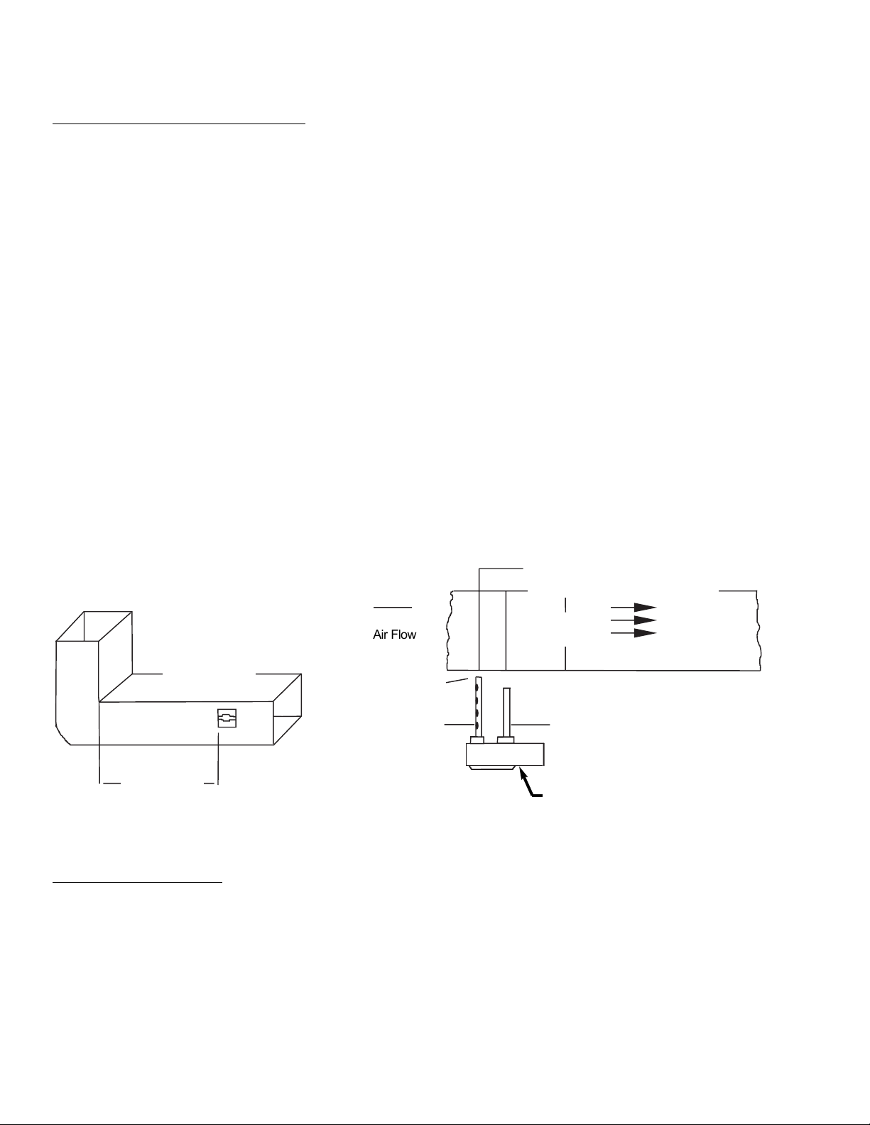
SAMPLING TUBES:
The principal of operation of a duct detector is based on the Venturi effect. Two tubes extend into the HVAC duct. Air flowing through the duct
is forced into the air intake tube via the air intake holes, and passes over the detector head. The air will be drawn out via the exhaust tube back
into the HVAC duct. (7” exhaust tube provided in the installation kit.)
When the particles of smoke suspended in the air stream reach the alarm threshold of the detector head, the unit will go into alarm.
REMOTE ACCESSORIES
:
Audible and visual alarm indicators, remote status indicators and remote reset/test switches can be accommodated by the
Firex Duct units by connecting to the DC voltage output terminals 16 thru 21 (see page 6 for details). These terminals are not supervised and
the current will only be present when the detector unit is in alarm. The remote pilot LED will be permanently illuminated when connected to the
output terminals. Trouble contacts cannot be connected to a fire alarm panel when the trouble (yellow) LED is connected. When connecting the
- trouble LED place a jumper between terminals 14 and 18.
MODEL 2650-660 Ionization
MODEL 2650-661 Photoelectric
INSTALLATION INSTRUCTIONS FOR
UNIVERSAL DUCT SMOKE DETECTORS
1
Duct Unit Installation
DUCT SMOKE LOCATION PRE-REQUISITES:
This guideline contains general information on duct smoke detector installation, but does not preclude the NFPA documents listed. Maple Chase
Company assumes no responsibility for improperly installed duct detectors. To determine the correct installation position for a Firex Duct Smoke
Detector, the following factors must be considered.
1) A uniform non turbulent airflow of between 500 ft/min to 4000 ft/min. must be present in the HVAC duct. To determine the duct
velocities examine the engineering specifications that define the expected velocities or use an Alnor model 6000P
velocity/meter (or equivalent).
2) In order to prevent stratification, duct smoke units, where possible, must be located a minimum of six duct widths down stream
from a source of turbulence i.e. elbows, deflector plates, filters, dampers, and inlets.
In installations where it is impossible to adhere to the six duct width requirement, units can be installed closer but as far from inlets, bends or
deflector plates as possible. Should this situation arise, check velocity readings in the duct prior to the duct smoke unit installation. Ensure the
duct smoke unit pressure differential complies with the unit specifications. The pressure differential between the input sampling tube and
exhaust tube for the Firex series duct smoke unit should be greater than 0.01 inches of water and less than 1.2 inches of water.
3) Identify a location for the installation of the duct unit that will permit easy access for viewing and serviceability.
4) Install duct units in the return air side of an HVAC unit prior to the air being exhausted from the building or diluted with outside air.
5) When installing duct smoke units down stream of filters, fires occurring in the filters will be detected, but if the filters become blocked
insufficient air flow through the duct unit will prevent the correct operation of the duct detector.
6) Where possible, install duct detectors upstream of air humidifiers and downstream of dehumidifiers.
7) To prevent false alarms, the duct detector should not be mounted in areas of extreme high or low temperatures, in areas where high
humidity exists or in areas where the duct may contain gases or excess dust.
SAMPLING TUBE ASSEMBL
Y:
Sampling tubes are to be ordered separately in one of the 3 standard lengths.
532 For duct widths of 1.0’ TO 2.5’
533 For duct widths of 2.5’ TO 5.0’
534 For duct widths of 5.0’ TO 10.0’
The standard sampling tubes are steel tubes with air intake holes drilled down the entire length of the tube. These tubes must be cut to length
and must span the entire width of the duct. Sampling tubes over 3.0 feet must be supported on the opposite side of the duct. To ensure the
correct operation of the sensing tube, the red end cap (red stopper in installation kit) must be inserted in the end of the air intake sampling tube.
Once the airflow direction has been determined, insert the inlet and exhaust tubes into the sampling tube connectors fitted to the back of the
duct smoke detector which are equipped with set screws. These connectors will allow the tubes to be correctly orientated and secured by
tightening the set screw. Ensure air intake sampling tube is positioned so that the inlet holes are facing the airflow.
2
6 Duct Widths
Minimum
Bend or Other
Obstruction
Insert Red Stopper
This End of Inlet Tube
Air Flow
Tube Support Hole Only for Ducts
Greater than 3 Feet Wide
Duct Width
Air Flow
Direction
Exhaust Tube
Installed Downstream of
Air Flow
Do Not Insert
Red Stopper
Set
Screw
Holes Face
Air Flow
Inlet Tube
2650 Duct Smoke
Detector

DUCT PREPARA
TION
:
For ease of duct unit installation, remove mounting template from the installation kit. Remove paper backing from the
mounting template and affix it to the duct at the desired location. Using the template as a guide, drill 4 mounting holes (3/32” diam.) for the
12 X 1/2” sheet metal screws packaged in the installation kit.
Drill or punch 1 3/8” holes for sampling tubes, using the template as a guide. Clean all holes.
MOUNTING DUCT SMOKE DETECT
OR:
After securing the sampling tubes to the duct smoke unit, or initially placing the tubes through the 1 3/8” holes drilled or punched in the HVAC
duct to accept the sampling tubes and then attaching them to the duct unit. Hold the duct unit assembly in position and
using 4# 12 X 1/2” sheet metal screws (Packaged in the installation kit) secure the duct smoke detector to the HVAC duct sheet metal work.
AIR SAMPLING VERIFICA
TION:
To ensure correct operation of the duct unit use a Magnehelic differential pressure gauge or Dwyer model 4000 to determine the differential
pressure between the inlet and exhaust tubes. The differential pressure between the two tubes should be greater than 0.01 inches of water
and less than 1.2 inches of water.
Model Number:
Detector Model Number: S60A Ionization Detector Head 2850 - 250
S60A Photoelectric Detector Head 2850 - 350
POWER REQUIREMENTS
QUIESCENT CURRENT ALARM CURRENT
24V AC 35 mA 24V AC 74mA
24V DC 15 mA 24V DC 48mA
QUIESCENT CURRENT
ALARM CURRENT
115V AC 25mA 115V AC 32mA
QUIESCENT CURRENT ALARM CURRENT
230V AC 12mA 230V AC 16mA
RELA
Y CONTACT RATINGS:
Alarm contacts: 2 form “C” rated at 12AMPS @ 125V AC resistive
Trouble contacts: 1 Set form “C” rated at 10AMPS @ 115V AC resistive
Air velocity: 500 to 3000 ft/min
Ambient temperature: Model 2650-660 -5
o
F to 155oF (-23oC to 68oC)
: Model 2650-661 -5
o
F to 100oF (-23oC to 38oC)
Humidity: 10% to 85% R.H. no condensation
Material: 18GA Steel back box, clear plastic cover
Finish: Gray paint
Dimensions: L-9 1/8” X W-7 1/4” X H-2 1/4”
Max. net wt.: 3 1/2 lbs.
Radioactive element: For Firex 2650-660 (Ionization model)
Americium 241, 0.9 micro curie
Do not expose to corrosive atmospheres.
3
PRODUCT SPECIFICATIONS
2650 - 660 Ionization
24V AC/DC, 115V AC, 230V AC
2650 - 661 Photoelectric
24V AC/DC, 115V AC, 230V AC
 Loading...