

Page 1

SM120X
RELAY / POWER SUPPLY MODULE
READ INSTRUCTIONS CAREFULLY AND COMPLETELY BEFORE INSTALLING.
Electrical Rating: 120V AC 60 HZ 0.08 AMP
Contact Rating: 10 AMPS @ 120 VAC
DC Output: 5 MA Max. (CURRENT LIMITED)
DESCRIPTION:
This module is only activated by a smoke alarm interconnect signal.
The relay portion of this module can be used to activate auxiliary warning devices such
as external bells and sirens,hallway or stairwell lighting. It provides isolated, (no internal
connection to 120 volts AC) normally open, and normally closed contacts.
The power supply portion can be used to connect spot type heat detectors (Rate of rise
or combined rate of rise and fixed temperature only) and manual pull stations
with interconnected multiple station alarms.
WARNING! Alarm and module wiring must conform to the electrical codes and local
codes in your area. In USA, it includes articles 210 and 300.3(B) of the U.S. National
Electrical Code ANSI/NFPA 70, and NFPA 72. The multiple station interconnect wiring to
the alarms must be run in the same raceway or cable as the AC power wiring. In addition,
resistance of the interconnect wiring shall be a maximum of 10 ohms.
the
All wiring should be performed by a licensed electrician. The module should be installed
in a UL listed junction box that has sufficient volume for proper installation. The electrical
circuit used to power the alarms and the module must be a 120 volt ac 60hz circuit which
cannot be turned off by a switch or a ground fault interrupter, it must be on 24 hours
a day. Since this module is 120 volt AC powered, it will not function during
an AC power failure, even if it is being used with the model 1275, 1275CA, 1276,
1276CA, 1285, 1285CA, 1296, i12040, i12040CA, i12060, i12060CA, i12080, PE120,
PE120CA, PI 2000, PI2000CA, KN-COSM-IB, KN-COSM-IBCA, HD135F, and HD135FCA,
alarms which have battery backup power.
WARNING: This device cannot be operated from power derived from a square wave,
modified square wave or modified sine wave inverter. These type of inverters are
sometimes used to supply power to the structure in off grid installations,such as solar or
wind derived power sources. These power sources produce high peak voltages that will
damage the device.
IMPORTANT: Whenever alarms and modules are interconnected they must be powered
from a single
wire as required by codes in your area. Do not use more than 1000 feet of wire
between the first and last device in the multi station system.
INSTALLATION INSTRUCTIONS:
This module should be installed in a UL listed junction box. All connections should be
made by a qualified electrician in accordance with the requirements of the national
electrical code and/or any other local codes having jurisdiction in your area.
Turn off the main power to the circuit. If you are also installing smoke alarms, heat
alarms, or CO alarms, wire them according to their specific owner’s manual. Refer to the
typical installation diagrams (Figures 1-4) included in this manual for your specific
application.
Connections on the Relay /Power Supply Module:
Black Wire AC Hot
White Wire AC Neutral
Red Wire Interconnect Signal
Blue Wire Common Contact
Yellow Wire Normally Closed Contact
Orange Wire Normally Open Contact
Gray Wire 9-Volt DC Output (5MA Max.)
After all connections are made, place the module inside a UL listed junction box, where the
alarm is installed, or in a remote location and use the appropriate electrical
CAUTION: The model SM120X should not be used to connect groups of alarms to a fire
alarm panel or to interconnect groups of fire alarms together.
Residential alarms do not latch in the alarm condition and they are self-resetting. If an
alarm connected to a module has the test button pushed or the alarm momentarily
activates, it will activate the module for as long as the unit is in alarm. If more than one
alarm is connected to the module and the module is tied to a control panel there will be no
way of knowing which unit caused the alarm.
circuit. When wiring the module remote from the alarm use UL/CSA listed
NON INDUCTIVE
5 AMPS @ 30 VDC
box cover.
The model SM120X module is for use with the following interconnectable models: Smoke
Alarms: 1235, 1235CA, 1275, 1275CA, 1276, 1276CA, 1285, 1285CA, 1296, i12020,
i12020CA, i12040, i1240CA, i12060, i12060CA, i12080, PE120, PE120CA, PI2000, and
PI2000CA, RF-SM-ACDC, CO/ Smoke Combo alarms: KN-COSM-IB and KN-COSM-IBCA,
and Heat Alarms, HD135F, and HD135FCA, all with red interconnect wires. Each module
is equivalent to one interconnect alarm, reduce the maximum number of interconnect
devices by one for each module used. Do not exceed the total number of devices
allowable in the interconnect system,
maximum number of units allowed when interconnecting. Do not exceed the
temperature or humidity limits of +40°F (4.4°C) to 100°F (37.8°C) (such as in garages
and unfinished attics) and 90% relative humidity for either the relay module or the
alarms.
NOTE: Only the Smoke portion of the: KN-COSM-IB and KN-COSM-IBCA combo alarms
will activate this module. If CO alarm models, KN-COB-IC, KN-COB-IC-CA, KN-COB-ICBCA, KN-COP-IC, KN-COP-IC-CA are included in the interconnect system, they will not
activate the SM120X module.
ATTENTION: The wiring connecting the module with the external devices is not
supervised. Be sure to test the operation of all the devices controlling the module or
controlled by the module. Devices controlled by the module can be tested by pushing the
test button on the alarms and verifying that the controlled device responds in the desired
manner.
Devices controlling the module can be tested by activating the device. Test pull stations
and spot type heat detectors after initial installation and each time you test your alarms.
Verify that the pull station and heat detectors sound all your interconnected alarms.
ATTENTION: Only use spot type heat
feature, as this type can be tested to validate operation. These detectors should be
tested following the manufacturers recommended procedure. This procedure typically
recommends using a hot air source (hand held hair dryer or heat gun) directed at the
detector from approximately 1 foot away.This will activate the rate of rise portion of the
detector and sound the interconnected alarms.
CAUTION: Remove the hot air source as soon as the alarms sound. This will prevent
activating the fixed temperature portion of the heat detector. The fixed temperature
element is a one-time device. Once activated it will not reset and the detector will have
to be replaced.
ADDITIONAL INSTALLATION INFORMATION: (Figures 1 and 2) If the desired function is to
switch off a device when the alarms sound, connect the yellow wire (NC) instead of the
orange wire (NO) to the supply side of the device. Be sure not to exceed the relay contact
ratings of the module. This module should not be used to control inductive loads with inrush
currents that will exceed the maximum contact ratings.
YEAR LIMITED WARRANTY:
ONE
Kidde warrants to the Purchaser that the enclosed module will be free of defects in
material, workmanship or design under normal use and service for a period of one year
from the date of purchase. The obligation to Kidde under this warranty is limited to
repairing or replacing any part which we find to be defective in material, workmanship,
or design, free of charge, to the customer, upon sending the relay module with proof of
date of purchase, postage and return postage prepaid, to Warranty Service dept. Kidde
Safety, 1016 Corporate Park Drive, Mebane, NC 27302 USA. (1-800-880-6788) This
warranty shall not apply to the relay module if it has been damaged, modified, abused or
altered after the date of purchase, or if it fails to operate due to improper maintenance
or inadequate AC electrical power.
The liability of Kidde or any of its parent or subsidiary corporations arising from the sale
of this accessory module or under the terms of this limited warranty shall not in any case
exceed the cost of the replacement of the module and, in no case, shall Kidde or any of
its parent or subsidiary
from the failure of the relay module or for the breach of this or any other warranties,
expressed or implied, even if the loss of damage is caused the company's negligence or
fault.
Since some states/provinces do not allow limitations on the duration of an implied
warranty or do not allow the exclusions or limitations of incidental or consequential
damages the above limitations or exclusions may not apply to you. While this warranty
gives you specific legal rights, you may also have other rights, which vary from state to
state, or province to province.The above warranty may not be altered except in writing
signed by both parties hereto.
corporations be liable for consequential loss or damages resulting
refer to the individual alarm owners manual for the
detectors incorporating a rate of rise
Manual P/N 810-1775 Rev. C
1201-7208-03
Page 2
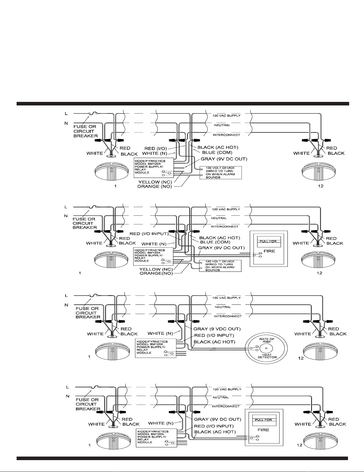
FIGURE 1 shows a typical installation of a relay / power supply module wired to switch
on 120 volt device when the alarms sound. In this configuration the common switch
contact (blue wire) is connected to the 120 volt supply. When the alarms sound the
module detects the signal on the interconnect line (red wire) and activates the relay. As
a result of this action, the orange wire (NO) supplies 120 volts to the device.
FIGURE 2 shows a typical installation of a manual pull station and a relay / power
supply module. In this configuration the module receives 120-volt power all the time. The
9-volt DC output (gray wire) is used to supply power to the pull station, and the relay
portion is used to control a 120-volt device configured to switch on when the module is
activated. The pull station switches the 9 volt signal from the module back into the
interconnect line.
FIGURE 1
Activating the pull station will sound the alarms and activate the relay portion of the
module.The common terminal of the switch contact (blue wire) is connected to the 120volt supply. When the alarms sound or the pull station is activated the module detects
the signal on the interconnect line (red wire) and activates the relay. As result of this
action, the orange wire (NO) supplies 120 volts to the device.
FIGURE 3 and 4 show the typical installation of a relay / power supply module and a
manual pull station or a spot type heat detector, interconnected with multiple station
alarms. In both of these configurations the connected device (manual pull station or spot
type heat detector) switches on the AC power to the module when the device is
activated. The module then supplies the DC interconnect signal (gray wire) needed to
activate all of the interconnected alarms.
NOTE: The switch contacts in the Pull Station or the Heat detector must be rated for 120
volts in this application.
FIGURE 2
FIGURE 3
FIGURE 4
Page 3

SM120X
MODULE DE RELAIS / ALIMENTATION
LISEZ LES DIRECTIVES AVEC SOIN ET EN ENTIER AVANT L’INSTALLATION
Débit électrique: 120 V CA 60 Hz 0,08 A
Intensité nominale: 10 A à 120 V CA
Sortie CC: 5 mA max. (courant limité)
DESCRIPTION:
Seul un signal provenant d'un avertisseur de fumée interconnecté peut enclencher
ce module. Le relais de ce module peut servir à activer les dispositifs d’alarme auxiliaries,
tels que les sonneries et les sirènes extérieures,l’éclairage dans les couloirs ou les escaliers. Il
offre des contacts de travail et des contacts de repos isolés (aucune connexion interne aux
120 volts CA).
Dans la section du module dédiée à l’alimentation,vous pouvez brancher des avertisseurs de
chaleur localisée (seulement ceux à taux d’augmentation ou à taux d’augmentation/de
température fixe combiné) ainsi que les postes d’incendie à levier manuel avec les
avertisseurs multipostes interconnectés.
MISE EN GARDE! L’installation électrique du module et de l’alarme doit être conforme aux
codes électriques et locaux de votre région.Le câblage d’interconnexion des stations multiples
aux alarmes doit passer par le même chemin de câbles ou câble que le câblage
plus,la résistance du câblage d’interconnexion doit être au maximum de 10 ohms.
Toutes les installations électriques doivent être exécutées par un électricien autorisé ayant son
permis. Le module doit être utilisé dans un boîtier homologué par UL qui possède un volume
suffisant pour une installation appropriée. Le circuit électrique utilisé pour mettre en marche
les alarmes et le module doit être un circuit de 120 volts CA 60 Hz qui ne peut être éteint ni
par un commutateur ni par un interrupteur de fuite à la terre. Il doit rester en marche 24
heures sur 24, étant donné qu’il s’agit d’un module à courant alternatif 120 volts. Il
ne fonctionnera pas pendant une panne de courant alternatif, même si on l’utilise avec les
modèles d’alarme 1275, 1275CA, 1276, 1276CA, 1285, 1285CA, 1296, i12040, i12040CA,
i12060, i12060CA, i12080, PE120, PE120CA, PI 2000, PI2000CA,KN-COSM-IB, KN-COSMIBCA, HD135F, ou HD135FCA, munis d’une pile de secours.
IMPORTANT: Lorsque les avertisseurs et les modules sont interconnectés, ils doivent
fonctionner à partir d’un circuit simple. Quand on installe le module à une certaine distance
de l’avertisseur,
locaux. N’utilisez pas plus de 1000 pieds de fil électrique entre le premier et le dernier
appareil d’un système multiposte.
DIRECTIVES D’INSTALLATION:
Ce module doit être installé dans un boîtier de jonction homologué UL. Toutes les connexions
doivent être faites par un électricien compétent conformément aux exigences du code
national de l’électricité et/ou de tous les autres codes locaux qui s’appliquent à votre région.
Coupez l’alimentation principale du circuit. Si vous installez aussi des avertisseurs de
fumée,de chaleur ou CO, veillez à ce que l’installation électrique soit conforme aux directives
du guide d’utilisation. Reportez-vous aux diagrammes d’installations types (schémas 1 à 4)
dans ce manuel pour trouver celle qui correspond à vos besoins.
Les connexions du module de relais/alimentation sont:
Fil orange contact de
Une fois toutes les connexions établies,placez le module à l’intérieur d’un boîtier de jonction
homologué UL, où l’alarme se trouve à être installée ou dans un endroit éloigné, et servezvous du couvercle de coffret électrique approprié.
ATTENTION: Le modèle SM120X ne doit pas être utilisé pour connecter des groupes
d’alarmes à un panneau d’avertisseur d’incendie ou pour interconnecter des groupes
d’alarmes ensemble.
Les avertisseurs résidentiels ne se verrouillent pas en mode d’alarme et ils sont munis d’un
dispositif de réenclenchement automatique.Si une alarme connectée à un module est munie
d’un bouton d’essai et que l’on appuie sur ce bouton ou que l’alarme se met en marche
momentanément,elle activera le module tant que l’unité sera en mode d’alarme. Si plus d’une
alarme est connectée au module et que le module est fixé à un tableau de contrôle, il n’y aura
pas moyen de savoir quelle unité a provoqué l’alarme.
on doit utiliser le fil homologué UL/CSA selon les prescriptions des codes
non inductif
5 A à 30 V CC
du c.a. De
fitca ACrion liF
ertuen ACcnalb liF
noixennocretni'd langiseguor liF
nummoc tcatnocuelb liF
soper ed tcatnocenuaj liF
travail
).xam Am 5( CC stlov 9 eitrossirg liF
Le modèle SM120X doit être utilisé avec ces avertisseurs interconnectables: avertisseurs de
fumée 1235,1235CA,1275, 1275CA,1276,1276CA,1285,1285CA, 1296,i12020,i12020CA
i12040, i1240CA, i12060, i12060CA,i12080, PE120, PE120CA,PI2000, et PI2000CA,RF-SMACDC;avertisseurs de fumée/CO combinés KN-COSM-IB et KN-COSM-IBCA et les avertisseurs
de chaleur HD135F et HD135FCA, tous équipés de fils d’interconnexion rouges. Chaque
module est l’équivalent d’un avertisseur interconnectable; réduisez de un le nombre
maximum d’appareils d’interconnexion pour chaque module utilisé. Ne dépassez pas le
nombre total d’appareils permis dans le système d’interconnexion. Reportez-vous au guide
d’utilisation pour les avertisseurrs individuels afin de savoir le nombre maximum d’unités
permises au moment de l’interconnexion. Ne dépassez pas les limites de température ou
d’humidité de +40°F (4,4°C) à 100°F (37,8°C) (tel que les garages et greniers non finis) et de
90% d’humidité relative soit pour le module, soit pour les avertisseurs.
REMARQUE: Seule la partie des avertisseurs 2-en-1 KN-COSM-IB et KN-COSM-IBCA qui
détecte la fumée enclenchera ce module. Si le système interconnecté comprend des
avertisseurs de CO KN-COB-IC ou KN-COP-IC, ceux-ci n’enclencheront pas le module
SM120X.
ATTENTION: On ne surveille pas les fils de connexion entre les appareils externes et le
module. Assurez-vous de vérifier le fonctionnement de tous les appareils qui contrôlent ou
qui sont contrôlés par le module. Pour vérifier les appareils contrôlés par le modul
sur le bouton d’essai dont les avertisseurs sont munis et assurez-vous que l’appareil contrôlé
réponde de la façon qu’il faut.
Pour vérifier les appareils qui contrôlent le module, activez l’appareil (postes d’incendie à
levier manuel et avertisseurs de chaleur localisée) après leur installation initiale et chaque fois
que vous vérifiez les avertisseurs. Assurez-vous que le poste d’incendie et les avertisseurs de
chaleur fassent sonner tous les avertisseurs interconnectés.
ATTENTION: N’utilisez que les avertisseurs de chaleur localisée qui se servent d’un
taux d’augmentation, parce qu’ils vous permettent la vérification du fonctionnement. Ils
doivent être vérifiés en suivant les directives recommandées par le fabricant. En général, ce
procédé exige une source de chaleur (un séchoir à cheveux ou un pistolet de chaleur) dirigée
vers l’avertisseur à une distance d’environ 1 pied. Une telle action enclenchera la partie du
module dédiée au taux d’augmentation et fera sonner les avertisseurs interconnectés.
MISE EN GARDE: Éloignez la source d’air chaud au moment où l’alarme se fait entendre.Ceci
évitera l’activation de la partie de l’avertisseur de chaleur dédiée au taux d’augmentation de
température fixe,qui est un dispositif à un seul usage. Une fois déclenché, ce
remet pas à zéro et il faudra remplacer l’avertisseur.
D’AUTRES CONSEILS SUR L’INSTALLATION: (Schémas 1 et 2). Si vous désirez qu’un appareil
se mette hors marche au moment où l’alarme sonne, branchez le fil jaune (CR) et non pas le
fil orange (CT) au côté de l’appareil qui s’occupe de l’alimentation.Assurez-vous que les cotes
des contacts de relais du module ne soient pas dépassées. Ce module ne doit pas être utilisé
pour contrôler des charges inductives à appels de courant qui dépassent les cotes du contact
maximum.
GARANTIE LIMITÉE DE 1 AN:
Kidde garantit à l’acheteur le module ci-joint contre tout défaut de matière, de fabrication ou
de conception, si l’appareil est utilisé normalement,et offre une garantie de service d’un an à
partir de la date d’achat. La responsabilité de Kidde en vertu de la présente garantie est
limitée à la réparation ou au remplacement de toute pièce défectueuse (défaut de matière, de
fabrication ou de conception), sans frais pour l’acheteur si ce dernier renvoie, port payé, le
module de relais avec une preuve d’achat à l’adresse suivante:Warranty Service Dept., Kidde
Safety, 1016 Corporate Park Driv
garantie ne s’applique pas aux modules de relais endommagés, modifiés, mal utilisés ou
changés après la date d’achat, ou s’ils ne fonctionnent plus en raison de l’entretien inexact ou
d’une alimentation électrique CA inappropriée.
La responsabilité de Kidde, de ses sociétés mères ou de ses filiales résultant de la vente du
présent module ou existant en vertu des dispositions de la présente garantie limitée ne peut
en aucun cas dépasser le prix lié au remplacement du module. De plus, Kidde, ni ses sociétés
mères ni ses filiales ne sont responsables d’aucune perte indirecte ni de dommages résultant
du non-fonctionnement du module ni du non-respect de la présente et d’autres garanties,
explicites ou implicites, même si la perte ou les dommages avaient été causés par la
négligence ou la faute de la société.
Étant donné que certaines provinces interdisent la limitation de la durée d’une garantie
implicite ou ne permettent ni l’exclusion ni la limitation de dommages accessoires ou
indirects, les limitations ou exclusions susmentionnées pourraient ne pas s’appliquer à vous.
Bien que cette garantie vous confère certains droits juridiques, vous pourriez bénéficier de
droits supplémentaires
modifiée qu’à condition que les parties concernées y consentent par écrit.
e, Mebane, NC 27302 USA. (1-800-880-6788) La présente
variant d’une province à l’autre. La présente garantie ne peut être
e,appuyez
dispositif ne se
,
Page 4
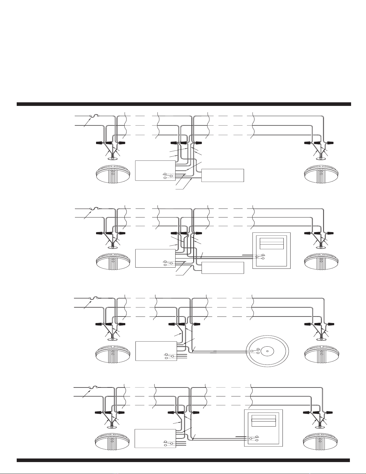
SCHÉMA 1 fait voir une installation type où le module de relais/alimentation est
SM120X
Module de relais /
alimentation
1
FUSIBLE OU
DISJONCTEUR
BLANC NOIR
ROUGE
BLANC (N)
NOIR (CA ACTIF)
BLEU (COM.)
GRIS (SORTIE 9V CC)
INTERCONNEXION
NEUTRE
ALIMENTATION 120 V CA
BLANC NOIR
ROUGE
12
L
N
APPAREIL 120 V
CONNECTÉ POUR SE
METTRE EN MARCHE
DÈS QUE L’ALARME SONNE
H
N
ROUGE (E/S)
ORANGE (CT)
JAUNE (CR)
TIREZ EN CAS
D’INCENDIE
SM120X
Module de relais /
alimentation
1
FUSIBLE OU
DISJONCTEUR
BLANC NOIR
ROUGE
BLANC (N)
NOIR (CA ACTIF)
BLEU (COM.)
GRIS (SORTIE 9V CC)
INTERCONNEXION
NEUTRE
ALIMENTATION 120 V CA
BLANC NOIR
ROUGE
12
L
N
APPAREIL 120 V
CONNECTÉ POUR SE
METTRE EN MARCHE
DÈS QUE L’ALARME SONNE
H
N
ROUGE (E/S)
ORANGE (CT)
JAUNE (CR)
AVERTISSEUR
DE CHALEUR
À TAUX
D’AUGMENTATION
SM120X
Module de relais /
alimentation
1
FUSIBLE OU
DISJONCTEUR
BLANC NOIR
ROUGE
BLANC (N)
GRIS (SORTIE 9V CC)
ROUGE (E/S)
NOIR (CA ACTIF)
INTERCONNEXION
NEUTRE
ALIMENTATION 120 V CA
BLANC NOIR
ROUGE
12
L
N
TIREZ EN CAS
D’INCENDIE
SM120X
Module de relais /
alimentation
1
FUSIBLE OU
DISJONCTEUR
BLANC NOIR
ROUGE
BLANC (N)
GRIS (SORTIE 9V CC)
ROUGE (E/S)
NOIR (CA ACTIF)
INTERCONNEXION
NEUTRE
ALIMENTATION 120 V CA
BLANC NOIR
ROUGE
12
L
N
configuré pour activer un appareil de 120 volts au moment où l’alarme se déclenche.
Dans cette configuration , le fil de contact commun (fil bleu) est branché sur la source
d’alimentation qui fournit 120 volts.Au moment où l’alarme sonne, le module détecte le
signal sur la ligne d’interconnexion (fil rouge) et déclenche le relais. Grâce à cette action,
le fil orange (CT) fournit 120 volts à l’appareil.
SCHÉMA 2 fait voir une installation type d’un poste d’incendie à levier manuel et un
module de relais/alimentation. Dans cette configuration, le module est alimenté en tout
temps de 120 voits. La sortie CC de 9 V (fil gris) alimente le poste d’incendie; le relais sert
à contrôler un appareil de 120 volts, configuré à se déclencher dès que le module est mis
en marche. Le poste d’incendie commute le signal de 9 volts du module à la ligne
d’interconnexion.
SCHÉMA 1
La mise en marche du poste d’incendie fera sonner les alarmes et déclenchera la section du
module dédiée au relais. La borne commune du contact du commutateur (fil bleu) est
branché sur la source d’alimentation de 120 volts. Dès que l’alarme sonne ou le poste
d’incendie se déclenche, le module détecte le signal sur la ligne d’interconnexion (fil rouge)
et met en marche le relais. Grâce à cette action, le fil orange (CT) fournit 120 volts à
l’appareil.
SCHÉMAS 3 et 4 font voir une installation type d’un module de relais/alimentation et d’un
poste d’incendie à levier manuel ou d’un avertisseur de chaleur localisée, interconnectés à
des avertisseurs multipostes. Dans ces deux configurations, l’appareil connecté (poste
d’incendie ou avertisseur de chaleur localisée) commute le courant CA au module dès
l’activation de l’appareil. Le module fournit ensuite le signal d’interconnexion CC (fil gris)
nécessaire à l’activation de tous les avertisseurs interconnectés.
REMARQUE: Il faut que les contacts de commutateur du poste d’incendie ou de
l’avertisseur de chaleur soit d’une tension nominale de 120 volts dans ce cas.
SCHÉMA 2
SCHÉMA 3
SCHÉMA 4
 Loading...