


AC3
For models: 1285
Smoke and Fire Alarm
User’s Guide
A.C. Wire-in Single and/or Multiple Station (24 Devices) Ionization Smoke Alarm with 9 Volt Battery Back Up and Battery Powered Safety Light.
Thank you for purchasing this smoke and fire alarm. It is an important part of your family’s home safety plan. You can trust this product to provide the highest quality safety protection. We know you expect nothing less when the lives of your family are at stake.
For your convenience, write down the following information. If you call our Consumer Hotline, these are the first questions you will be asked.
Smoke Alarm Model Number (located on back of alarm):
Date Code (located on back of alarm). The National Fire Protection Association (NFPA) and the manufacturer recommends replacing this alarm ten years from the date code:
Date of Purchase:
Where Purchased:


LISTED

This product is designed to detect products of combustion using the ionization technique. It contains 0.9 microcurie of Americium 241, a radioactive material. Distributed under U.S. NRC License No. 32- 23858-01E. Manufactured in compliance with U.S. NRC safety criteria in 10 CFR 32.27. The purchaser is exempt from any regulatory requirements.
WARNING! REMOVAL OF THE SMOKE ALARM BATTERY AND DISCONNECTING OR LOSS OF A.C. POWER WILL RENDER THE SMOKE ALARM INOPERATIVE.
ELECTRICAL RATING: 120 VAC, 60HZ, 80mA maximum per alarm (maximum 80mA for originating unit with 24 devices interconnected).
IMPORTANT! READ ALL INSTRUCTIONS BEFORE INSTALLATION AND KEEP THIS MANUAL NEAR THE ALARM FOR FUTURE REFERENCE.
CONTENTS OF THIS MANUAL
1 -- RECOMMENDED LOCATIONS FOR SMOKE ALARMS
2 -- LOCATIONS TO AVOID
3 -- INSTALLATION INSTRUCTIONS
4 -- OPERATION AND TESTING
5 -- NUISANCE ALARMS
6 -- MAINTENANCE
7 -- LIMITATIONS OF SMOKE ALARMS
8 -- GOOD SAFETY HABITS
9 -- NRC INFORMATION
10 -- NFPA PROTECTION STANDARD 72
11 -- CALIFORNIA STATE FIRE MARSHAL REQUIRED INFORMATION
12 -- SERVICE AND WARRANTY
This smoke alarm uses an extremely small amount of radioactive element in the ionization chamber (see Section 9). Do not try to repair the smoke alarm yourself. Refer to the instructions in Section 12 for service.
1. RECOMMENDED LOCATIONS FOR ALARMS
•Locate the first alarm in the immediate area of the bedrooms. Try to protect the exit path as the bedrooms are usually farthest from the exit. If more than one sleeping area exists, locate additional alarms in each sleeping area.
•Locate additional alarms to protect any stairway as stairways act like chimneys for smoke and heat.
•Locate at least one alarm on every floor level.
•Locate an alarm in every bedroom.
•Locate an alarm in every room where electrical appliances are operated (i.e. portable heaters or humidifiers).
•Locate an alarm in every room where someone sleeps with the door closed. The closed door may prevent the alarm from waking the sleeper.
•Smoke, heat, and combustion products rise to the ceiling and spread horizontally. Mounting the smoke alarm on the ceiling in the center of the room places it closest to all points in the room. Ceiling mounting is preferred in ordinary residential construction.
•For mobile home installation, select locations carefully to avoid thermal barriers that may form at the ceiling. For more details, see MOBILE HOME INSTALLATION below.
•When mounting an alarm on the ceiling, locate it at a minimum of 4” (10 cm) from the side wal (see Diagram A).
•When mounting the alarm on the wall, use an inside wall with the top edge of the alarm at a minimum of 4” (10 cm) and a maximum of 12” (30.5 cm) below the ceiling. (see Diagram A).
•Put smoke alarms at both ends of a bedroom hallway or large room if the hallway or room is more than 30 feet (9.1 m) long.
•Install Smoke Alarms on sloped, peaked or cathedral ceilings at or within 3ft (0.9m)of the highest
point (measured horizontally). NFPA 72 states: “Smoke alarms in rooms with ceiling slopes greater than 1 foot in 8 feet (.3m in 2.4m) horizontally shall be located on the high side of the room.”
NFPA 72 states: “A row of alarms shall be spaced and located within 3 ft (0.9m) of the peak of the ceiling measured horizontally” (see diagram ”C”).
●Smoke Alarms for Minimum Protection
●Smoke Alarms for Additional Protection ▲ Ionization Type Smoke Alarms with
“Hush” Control or Photoelectric Type
DIAGRAM “B”
ANYWHERE
IN THIS AREA
DIAGRAM “A”
 3 ft
3 ft
 3 ft
3 ft
(0.9m) (0.9m)
HORIZONTAL DISTANCE
FROM PEAK
DIAGRAM “C”
MOBILE HOME INSTALLATION
Mobile homes built in the past five to seven years have been designed to be energy efficient. Install smoke alarms as recommended above (refer to RECOMMENDED LOCATIONS and Diagram A).
In mobile homes that are not well insulated compared to present standards, extreme heat or cold can be transferred from the outside to the inside through poorly insulated walls and roof. This may create a thermal barrier which can prevent the smoke from reaching an alarm mounted on the ceiling. In such units, install the smoke alarm on an inside wall with the top edge of the alarm at a minimum of 4” (10 cm) and a maximum of 12” (30.5 cm) below the ceiling (see Diagram A).
If you are not sure about the insulation in your mobile home, or if you notice that the outer walls and ceiling are either hot or cold, install the alarm on an inside wall. For minimum protection, install at least one alarm close to the bedrooms. For additional protection, see SINGLE FLOOR PLAN in Diagram B.
WARNING: TEST YOUR SMOKE ALARM OPERATION AFTER R.V. OR MOBILE HOME VEHICLE HAS BEEN IN STORAGE, BEFORE EACH TRIP AND AT LEAST ONCE A WEEK DURING USE.
2. LOCATIONS TO AVOID
•In the garage. Products of combustion are present when you start your automobile.
•Less than 4” (10cm) from the peak of an “A” frame type ceiling.
•In an area where the temperature may fall below 40ºF or rise above 100ºF.
•In dusty areas. Dust particles may cause nuisance alarms or failure to alarm.
•In very humid areas. Moisture or steam can cause nuisance alarms.
•In insect infested areas.
•Smoke alarms should not be installed within 3 ft. (.9m) of the following: the door to a kitchen, the door to a bathroom containing a tub or shower, forced air ducts used for heating or cooling, ceiling or whole house ventilating fans, or other high air flow areas.
•Kitchens. Normal cooking may cause nuisance alarms. If a kitchen alarm is desired, it should have an alarm silence feature or be a photoelectric type.
•Near fluorescent lights. Electronic “noise” may cause nuisance alarms.
3. INSTALLATION INSTRUCTIONS
WIRING REQUIREMENTS
•This smoke alarm should be installed on a U.L. listed or recognized junction box. All connections should be made by a qualified electrician and must conform to article 760 of the U.S. National Electrical Code, NFPA 72 and/or any other codes having jurisdiction in your area.
•The appropriate power source is 120 Volt A.C. Single Phase supplied from a non-switchable circuit which is not protected by a ground fault interrupter.
WIRING INSTRUCTIONS FOR A.C. QUICK CONNECT HARNESS
CAUTION! TURN OFF THE MAIN POWER TO THE CIRCUIT BEFORE WIRING THE ALARM.
•For alarms that are used as single station, DO NOT CONNECT THE RED WIRE TO ANYTHING. Leave the red wire insulating cap in place to make certain that the red wire cannot contact any metal parts or the electrical box.
•When alarms are interconnected, all interconnected units must be powered from a single circuit.
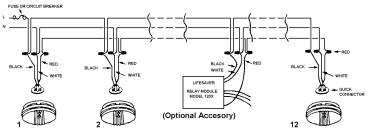
•A maximum of 24 Lifesaver devices may be interconnected in a multiple station arrangement. The interconnect system should not exceed the NFPA interconnect limit of 12 smoke alarms and/or 18 alarms total (smoke, heat, etc.) With 18 alarms interconnected, it is still possible to interconnect up to a total of 6 remote signaling devices and/or relay modules.
•When mixing models which have battery backup (1275, 1275H, 1285, PE 120, HD135F) with models without battery backup (1235, 120X, SL177i) be advised that the models without battery backup will not respond during an AC power failure.
•The maximum wire run distance between the first and last unit in an interconnected system is 1000 feet.
•Figure 1 illustrates interconnection wiring. Improper connection will result in damage to the alarm, failure to operate, or a shock hazard.
•Make certain alarms are wired to a continuous (non-switched) power line. NOTE: Use standard UL
listed household wire (18 gauge or larger as required by local codes) available at all electrical supply stores and most hardware stores.
FIGURE 1 INTERCONNECT WIRING DIAGRAM
|
|
Optional Accessory |
|
WIRES ON ALARM HARNESS |
CONNECTED TO |
||
Black |
Hot Side of A.C. Line |
||
White |
Neutral Side of A.C. Line |
||
Red |
Interconnect Lines (Red Wires) of Other |
||
|
Units in the Multiple Station Set up |
||
BATTERY INSTALLATION
See Maintenance (Section 6) for battery installation
CAUTION! IF BOTH BATTERY REMINDER FINGERS ARE NOT HELD DOWN IN THE BATTERY COMPARTMENT BY THE BATTERIES, THE BATTERY DOOR WILL NOT CLOSE, THE A.C. QUICK CONNECTOR WILL NOT ATTACH TO THE ALARM, AND THE ALARM WILL NOT ATTACH TO THE TRIM RING (SEE SECTION 6, FIGURE 6).
MOUNTING INSTRUCTIONS
CAUTION: THIS UNIT IS SEALED. THE COVER IS NOT REMOVABLE!
1.Remove the trim ring from the back of the alarm by holding the trim ring and twisting the alarm in the direction indicated by the “OFF” arrow on the alarm cover.
2.After selecting the proper smoke alarm location as described in Section 1 and wiring the A.C. QUICK CONNECT harness as described in the WIRING INSTRUCTIONS, attach the trim ring to the electrical box (see Figure 2).
3.Use a screwdriver to punch out only the pair of holes in the trim ring that match your type of electrical box or plaster ring. Mount the trim ring to the electrical box, using the appropriate holes. NOTE: Use the circle, square and octagon markings near each mounting hole in the trim ring to help you select the correct mounting holes (see Figure 2).
4.Pull the A.C. QUICK CONNECTOR through the center hole in the trim ring and mount the ring, making sure that the mounting screws are positioned in the small ends of the keyholes before tightening the screws (see Figure 2).
5.Plug the A.C. QUICK CONNECTOR into the back of the alarm (see Figure 3), making sure that the locks on the connector snap into place. Then push the excess wire back into the electrical box through the hole in the center of the trim ring.
 Loading...