

Page 1

ZX
MULTI-CHANNELAMPLIFIER
ZX350.4, ZX650.4, ZX850.4
©2006 Stillwater Designs
English Version
Versión Español
Amplificador del la Serie ZX.4
Manual del Propietario
Deutsche Version
Stereoverstärker der ZX.4-Serie
Benutzerhandbuch
Version Française
Amplificateur de série ZX.4
Manuel d'utilisation
Page 2
Installation . . . as easy as 1, 2, 3
1. Mounting Choose a structurally sound location to mount your Kicker amplifier. The controls on the
top of the amplifier need to be accessible for adjustment. Make sure there are no items behind the area
where the screws will be driven. Choose a location that allows at least 4” (10cm) of open ventilation for
the amplifier. If possible, mount the amplifier in the climate-controlled passenger compartment. Drill four
holes using a 7/64” (3mm) bit and use the supplied #8 screws to mount the amplifier.
2. Wiring Disconnect the vehicle’s battery to avoid an electrical short. Then connect the ground wire
to the amplifier. Make the ground wire short, 24” (60cm) or less, and connect it to a paint-and
corrosion-free solid-metal area of the vehicle's chassis. Adding an additional ground wire between the
battery's negative post and the vehicle chassis
of this same gauge (or larger) is recommended.
Use a twisted pair(s) of RCA (low-level)
interconnect cable to feed the audio signal to
the amplifier. If you are using only one pair of
RCA inputs, connect the RCA cable to the AMP
1 inputs. Push the fader button out, and all four
channels will work with a single pair of RCA
input cable. Push the fader button in, when
using two pairs of RCA input cables. Keep the
RCA cable away from factory wiring harnesses
and other power wiring. If you need to cross this
wiring, cross it at a 90 degree angle.
Only use speaker wire (high-level) inputs if
your source unit does not have RCA type outputs. If you are using only one pair of high-level inputs,
connect the speaker wire to the AMP 1 input. Push the fader button out, and all four channels will work
with a single high-level input cable. Push the fader button in, when using both sets of high-level inputs.
Install a fuse within 18” (45cm) of the battery and in-line with the power cable connected to your
amplifier. If you ever need to remove the amplifier from the vehicle after it has been installed, the ground
wire should be the last wire disconnected from the amplifier--just the opposite as when you installed it.
See the chart below for power and ground wire size, and fusing recommendations.
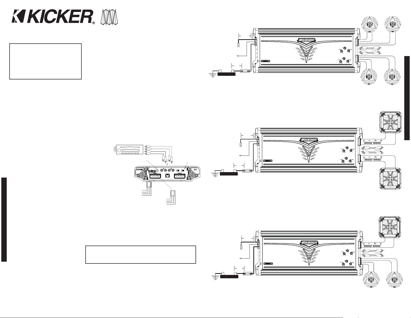
3. Configuration The following
diagrams show the most common
configurations for your Kicker ZX series
amplifier.
TwoChannelOperation (Stereo) These ZX amplifiers are capable of operating into a minimum
impedance of 2 ohms per channel in stereo operation. See Figure 2.
BridgedOperation (Mono) ZX.4 series amplifiers are capable of operating into a minimum
impedance of 4 ohms when in bridged operation. See Figure 3.
StereoBridgedOperation (Simultaneously) The ZX.4 series amplifiers are capable of operating into a
minimum impedance of 4 ohms bridged and 2 ohms per channel in stereo operation. See Figure 4.
INSTALLATION
ZX.4AMPLIFIER
ZX350.4 / ZX650.4 / ZX850.4
FourChannelModels:
ZX.4SeriesAmplifier
Owner’sManual
Congratulations on your
KICKER purchase
Please record your purchase
information and keep your sales
receipt for validation of warranty.
Authorized Kicker Dealer:
Purchase Date:
Amplifier Model Number:
Amplifier Serial Number:
__________________________
__________________________
__________________________
__________________________
killers trk7“on Top”
AMP 1 INPUT
REMOTE BASS
RL
L+ L- R+ R- L+ L- R+ R-
AMP
1
AMP
2
2
AMP 2 INPUT
RL
HI-LEVEL
INPUT
+ - - +
1
HI-LEVEL
INPUT
+ - - +
OFF HI LO
XOVER
OFF HI LO
XOVER
21
FADER
ModelZX350.4 Fuse40A PowerGroundWire 8GA
ModelZX650.4 Fuse80A PowerGroundWire 4GA
ModelZX850.4 Fuse120A PowerGroundWire 2GA
Note: To get the best performance from your new Kicker Amplifier, we recommend using genuine Kicker Accessories and Wiring.
2 3
Figure 2
Figure 3
Figure 4
CONFIGURATION
Figure 1
Use only one type of signal input to the amplifier,
either RCA Cable or Speaker Wire
RCA Cable
(Low-Level)
AMP 1
Speaker Wire
(High-Level
Output)
Speaker Wire
(High-Level Input)
AMP 1
Left +
Left Right Right +
Speaker Wire
(High-Level Input)
AMP 2
Fader Button: Push in for
2 pairs of inputs, push out
for a single pair of inputs.
RCA Cable
(Low-Level)
AMP 2
Left +
Left Right Right +
Crossover
Switches
Minimum impedance of 2 ohms per channel in stereo operation
Right Speaker AMP 2
Left Speaker AMP 2
Battery
Battery
Battery
Remote
Turn-On
+12V
Remote
Turn-On
+12V
Remote
Turn-On
(45cm)
Or Less
+12V
Ground
18"
Ground
(45cm)
18"
Or Less
Ground
(45cm)
18"
Or Less
(60cm)
24"
Or Less
Fuse
(60cm)
Or Less
Or Less
24"
Fuse
(60cm)
24"
Fuse
Minimum impedance of 4 ohms when in bridged operation
Minimum impedance of 4 ohms when in bridged operation
and 2 ohms per channel in stereo operation
AMP2
AMP1
AMP2
AMP1
AMP2
AMP1
+
-
-
Signal In AMP 2
Signal In AMP 1
+
-
-+
+
Left Speaker AMP 1
Mono Speaker AMP 2
Mono Speaker AMP 1
Mono Speaker AMP 2
+
Left Speaker AMP 1
Right Speaker AMP 1
-
+
-
-
+
Signal In AMP 2
Signal In AMP 1
-
+
Signal In AMP 2
Signal In AMP 1
-
+
Right Speaker AMP 1
Page 3
Operation
Your Kicker ZX.4 series amplifier has six rotary controls on top and two switches on the end-panel.
Before turning on the system for the first time, turn the six rotary controls on the top of the amplifier to
the full counter-clockwise position.
1. CrossoverSwitch The crossover switches on the end-panel are for setting the internal crossovers.
In the OFF position the amplifier passes
a full-range signal to the speakers. Use
the LO position when connected to a
subwoofer. The HI position should be
selected when connected to speakers,
which you do not want to receive any
sub-bass information. Never change
the crossover "OFF/HI/LO" switch
setting with the audio system on!
See Figure 1.
2. InputGainControl The input gain control is not a volume control. It matches the output of the
source unit to the input level of the amplifier. Turn the source unit up to about 3/4 volume (if the source
unit goes to 30, turn it to 25). Next, slowly turn (clockwise) the gain on the amplifier up until you can
hear audible distortion, then turn it down a little. Adjust AMP 1, then proceed to AMP 2.
3. BassBoostControl The bass boost control is designed to give you increased output 0 - 18dB at
40 Hz. The setting for this control is subjective. If you turn it up, you must go back and adjust the input
gain control to avoid clipping the amplifier.
4. CrossoverControl The setting for this control is subjective; 80Hz is a good place to start.
5. RemoteBass(Level Control) When using AMP 2 as a subwoofer amplifier, set the crossover
switch to LO pass and you will have the ability to control the level of the subwoofers remotely. To mount
the remote bass level control, simply
screw the metal bracket to the
chosen location. Then slide the
housing onto the bracket until it
snaps into place. Run the cable from
the controller to the “Remote Bass”
jack on the amplifier chassis.
TroubleShooting
If your amplifier does not appear to be
working, check the obvious things first
such as blown fuses, poor or incorrect
wiring connections, incorrect setting of
crossover switch and gain controls, etc.
There are two LEDs on the top of your
Kicker ZX series amplifier, one green and one red. When the green LED is lit this indicates the amplifier is turned on
and no trouble exists. If the green LED turns off and the red LED is lit, this indicates that the protection circuitry (SORT)
is engaged.
Green LED off, no output? With a Volt Ohm Meter (VOM) check the following: 1) +12 volt power terminal
(should read +12V to +16V) 2) Remote turn-on terminal (should read +12V to +16V) 3) Check for reversed power
and ground connections 4) Ground terminal, for proper conductivity.
Green LED on, no output? Check the following: 1) RCA connections 2) Test speaker outputs with a “known”
good speaker. 3) Substitute source unit with a “known” good source unit. 4) Check for a signal in the RCA cable
feeding the amplifier with the “AC” test position selected on the VOM meter.
Red LED on, no output? 1) Amplifier is very hot. Thermal protection is engaged. Test for proper impedance at
the speaker terminals with a VOM meter (see the diagrams in this manual for minimum recommended impedance and
multiple speaker wiring suggestions). Also check for adequate airflow around the amplifier. 2) Amplifier shuts down
only while vehicle is running. Voltage protection circuitry is engaged. Voltage to the amplifier is not within the 9-16
volt operating range. Have the vehicle's charging and electrical system inspected. 3) Amplifier will only play at low
volume levels. Short circuit protection is engaged. Check for speaker wires shorted to each other or to the vehicle
chassis. Check for damaged speakers, or speaker(s) operating below the minimum recommended impedance.
No output from one channel? 1) Check the balance control on source unit 2) Check the RCA (or speaker input)
and speaker output connections for the channel 3) Swap the RCA (or speaker input) cable from left to right. If the
problem changes sides then you have a bad RCA (or speaker input) cable or source unit problem. 4) Swap the
speaker output wire from left to right. If the problem changes sides then you have a bad speaker cable, passive
crossover network and/or speaker.
Alternator noise-whining sound with engine’s RPM? 1) Check for damaged RCA (or speaker input) cable
2) Check the routing of RCA (or speaker input) cable 3) Check the source unit for proper grounding 4) Check the
gain settings and turn them down if they are set too high.
Poor stereo image or reduced bass response? Check system phasing by turning the balance control from left
to right. If there is more bass output when turned to either side, then check your speaker wiring, passive crossover
networks and speaker terminals for proper positive and negative connections. Reverse a speaker connection from
positive to negative on the stereo/subwoofer channel(s); if the bass improves, the speaker was out of phase.
Ground-Loop Noise? If you are using only one pair of RCA inputs, connect the RCA cable to the AMP 1 inputs.
No Fader? When using both sets of low-level (RCA) or high-level (speaker wire) inputs, the fader button must be
pushed in.
If you have more questions about the installation or operation of your new KICKER product, see the Authorized KICKER Dealer where you
made your purchase. For more advice on installation, click on the SUPPORT tab on the Kicker homepage, www.kicker.com. Choose the
TECHNICAL SUPPORT tab, choose the subject you are interested in, and then download or view the corresponding information.
Please E-mail support@kicker.com or call Technical Services (405) 624-8583 for unanswered or specific questions.
Please Note: Modern high performance speakers have a lower DC Resistance than what used to be available. The Kicker Coaxial and
Component speakers are rated at four ohms (some DC Resistances may be as low as 3 ohms) and work with any amplifier designed to
operate at a four ohm load. If you want to use two Kicker Coaxial or Component speakers on a single channel of your amplifier wire the
speakers in series. This will improve the sound quality, lower the total harmonic distortion and lessen the thermal load at the amplifier. This
may prevent an amplifier from shutting down, due to over-current protection circuitry.
CAUTION: When jump starting the vehicle, be sure that connections made with jumper cables are correct. Improper connections can
result in blown amplifier fuses as well as the failure of other critical systems in the vehicle.
Performance
Model ZX350.4 ZX650.4 ZX850.4
RMS Power in Watts, all channels driven
@14.4V, 4Ω Stereo ≤1% THD+N 60 x 4 120 x 4 175 x 4
@14.4V, 2Ω Stereo, ≤1% THD+N 90 x 4 170 x 4 215 x 4
@14.4V, 4Ω Mono, ≤1% THD+N 175 x 2 325 x 2 425 x 2
Length: 13 1/2” (342mm) 20” (507mm) 23 1/4” (590mm)
Specifications common to all models:
Height: 2 1/8” (54mm)
Width: 9 5/8” (244mm)
Frequency Response, ± 0.5 dB: 20 Hz - 20 kHz
Signal-to-Noise Ratio: >95 dB, a-weighted, re: rated power
Input Sensitivity: 125 mV - 5 V low level, 250 mV - 10 V high level
Electronic Crossover: Variable HI, LO or OFF (bypass), 50 - 200Hz, 12dB per octave
Bass Boost: Variable 0 to +18 dB boost @ 40 Hz
ZX.4AMPLIFIER
4 5
Model ZX350.4
60 x 4 @ 4 ohms, 14.4Vdc, 1% THD, CEA-2006 (Watts)
Signal to Noise Ratio -98 CEA-2006 (ref: 1W, A-weighted)
Model ZX650.4
120 x 4 @ 4 ohms, 14.4Vdc, 1% THD, CEA-2006 (Watts)
Signal to Noise Ratio -95 CEA-2006 (ref: 1W, A-weighted)
Model ZX850.4
175 x 4 @ 4 ohms
, 14.4Vdc, 1% THD, CEA-2006 (Watts)
Signal to Noise Ratio -94 CEA-2006 (ref: 1W, A-weighted)
PERFORMANCE
OPERATION
L-
L+
Figure 5
Crossover Control AMP 1
50 - 200Hz, 12dB/Oct
Input Gain Control AMP 1
Low Level: 125mV - 5V, High Level: 250mV - 10 V
Bass Boost Control AMP 1
0 to +18dB boost @ 40Hz
Figure 6
Mount the metal bracket
Back View
Side View
4 Conductor
Phone Cable
Slide the housing until it snaps into the metal bracket
All specifications and performance figures are subject to change. Please visit the www.kicker.com for the most current information.
HI-LEVEL
HI-LEVEL
2
1
INPUT
INPUT
+ - - +
+ - - +
FADER
AMP
1
L+ L- R+ R- L+ L- R+ R-
AMP 1 INPUT
REMOTE BASS
RL
RL
AMP 2 INPUT
OFF HI LO
OFF HI LO
XOVER
XOVER
21
AMP
2
Page 4

6 7
Instalación tan fácil como 1, 2 y 3
1. Montaje Escoja una ubicación estructuralmente sólida para instalar su amplificador Kicker. Los controles en la
parte superior del amplificador tienen que ser accesibles para ajuste. Asegúrese de que no haya ningún artículo
detrás del área donde los tornillos serán atornillados. Escoja una ubicación que deje al menos 4" (10 cm) de
ventilación abierta para el amplificador. Si es posible, monte el amplificador en el compartimiento del pasajero
regulado para el clima. Perfore cuatro agujeros usando una broca de 7/64" (3 mm) y use los tornillos # 8
proporcionados para instalar el amplificador.
2. Cableado Desconecte la batería del vehículo para evitar un cortocircuito eléctrico. Luego conecte el cable de
tierra al amplificador. Acorte el cable de tierra a 24" (60 cm) o menos, y conéctelo a un área de metal sólido libre de
corrosión y pintura del chasis del vehículo. Se
recomienda agregar un cable de tierra adicional entre el
polo negativo de la batería y el chasis del vehículo de
este medidor (o más grande).
Use cable(s) de interconexión de par(es) trenzado(s)
tipo RCA (de bajo nivel) para alimentar la señal de audio
al amplificador. Si usted está usando solamente un par
de entradas de RCA, conecte el cable RCA a las
entradas de AMP 1. Presione el botón de atenuación
"Fader" para que hacia afuera, y todos los cuatro
canales funcionarán con un solo par de cables de
entrada RCA. Presione el botón de atenuación o
"Fader" para que quede hacia adentro, cuando se usen
dos pares de cables de entrada RCA. Mantenga el
cable RCA lejos de los arneses del cableado de fábrica
y otro cableado de energía. Si usted tiene que cruzar
este cableado, crúcelo en un ángulo de 90 grados.
Sólo use las entradas para el cable del altoparlante (alto nivel) si su unidad de origen no tiene salidas de tipo RCA.
Si usted está usando solamente un par de entradas de alto nivel, conecte el cable del altoparlante al AMP 1. Presione
el botón de atenuación o "Fader" para que quede hacia afuera, y todos los cuatro canales funcionarán con un solo
cable de entrada de alto nivel. Presione el botón de atenuación o "Fader" para que quede hacia adentro, cuando se
usen ambos juegos de entradas de alto nivel.
Instale un fusible dentro de 18" (45 cm) de la batería y en línea con el cable de energía eléctrica conectado a su
amplificador. Si usted alguna vez tiene que retirar el amplificador del vehículo después de que haya sido instalado, el
cable de tierra deberá ser el último cable que se desconecte del amplificador, sólo lo contrario a la manera como
usted lo instaló. Vea la tabla abajo para ver las recomendaciones del tamaño del cable de alimentación y para
protección con fusibles.
3. Configuración los siguientes diagramas
indican las configuraciones más comunes
para su amplificador Kicker de la serie ZX.
Funcionamiento de dos canales (estéreo) Estos amplificadores ZX son capaces de funcionar en una
impedancia mínima de 2 ohmios por canal en funcionamiento estéreo. Vea la Figura 2.
Funcionamiento Cruzado (monofónico) los amplificadores de la serie ZX.4 son capaces de funcionar en una
impedancia mínima de 4 ohmios cuando estén en funcionamiento cruzado. Vea la Figura 3.
Funcionamiento cruzado y en estéreo simultáneamente Los amplificadores de la serie ZX.4 son capaces de
funcionar en una impedancia mínima de 4 ohmios cruzada y 2 ohmios por canal en funcionamiento en estéreo. Vea la
Figura 4.
INSTALACIÓN
AMPLIFICADOR ZX.4
ZX350.4 /ZX650.4 /ZX850.4
Modelos de Cuatro Canales:
Amplificador de la Serie ZX.4
Manual del Propietario
¡Felicidades por su
compra de KICKER
Por favor registre su información de
compra y mantenga su recibo de
ventas para validación de la garantía.
Distribuidor autorizado de Kicker:
Fecha de compra:
Número de modelo del amplificador:
Número de serie del amplificador:
__________________________
__________________________
__________________________
__________________________
Figura 2
Figura 3
Figura 4
CONFIGURACIÓN
Impedancia mínima de 2 ohmios por canal en funcionamiento
estéreo
Impedancia mínima de 4 ohmios cuando este en funcionamiento
cruzado
Impedancia mínima de 4 ohmios cuando se esté en funcionamiento
cruzado y y 2 ohmios por canal en funcionamiento en estéreo
Altoparlante Derecho
AMP2
Altoparlante monofónico
AMP 2
Altoparlante monofónico
AMP 1
Altoparlante monofónico
AMP 2
Altoparlante Izquierdo
AMP2
Señal en AMP 2
Tierra
Batería
Fusible
O menos
O menos
Encendido
Remoto
Tierra
Batería
Fusible
O menos
O menos
Encendido
Remoto
Tierra
Batería
Fusible
O menos
O menos
Encendido
Remoto
Señal en AMP 1
Señal en AMP 2
CLABEADO CRUZADO
CLABEADO CRUZADO
CLABEADO CRUZADO
Señal en AMP 1
Señal en AMP 2
Señal en AMP 1
Altoparlante Izquierdo
AMP 1
Altoparlante Derecho
AMP 1
Altoparlante Izquierdo
AMP 1
Altoparlante Derecho
AMP 1
killers trk7“on Top”
AMP 1 INPUT
REMOTE BASS
RL
L+ L- R+ R- L+ L- R+ R-
AMP
1
AMP
2
2
AMP 2 INPUT
RL
HI-LEVEL
INPUT
+ - - +
1
HI-LEVEL
INPUT
+ - - +
OFF HI LO
XOVER
OFF HI LO
XOVER
21
FADER
ModeloZX350.4 Fusible40A CablePowerGround 8GA
ModeloZX650.4 Fusible80A CablePowerGround 4GA
ModeloZX850.4 Fusible120A CablePowerGround 2GA
Figura 1
Use solamente un tipo de entrada de señal para el
amplificador, ya sea para cable RCA o cable para altavoces
Cable RCA
(Bajo Nivel)
AMP 1
Cable para
altoparlante
(Salida de alto
nivel)
Cable del altoparlante
(Entrada de alto nivel)
AMP 1
Izquierda +
Izquierda Derecho Derecho +
Cable del altoparlante
(Entrada de alto nivel)
AMP 2
Botón de atenuación o "Fader": presione
para que quede hacia adentro para 2 pares
de entradas, presione para que quede
hacia fuera para un solo para de entradas.
Cable RCA
(Bajo Nivel)
AMP 2
Izquierda +
Izquierda Derecho Derecho +
Interruptores
de cruce
Nota: Para obtener el mejor rendimiento de su nuevo amplificador Kicker, recomendamos usar accesorios y cableado genuinos de Kicker.
Nota: Todas las especificaciones y rendimiento de las cifras están sujetos a cambios. Por favor visite www.kicker.com para obtener la información más reciente.
Minimum impedance of 2 ohms per channel in stereo operation
Right Speaker AMP 2
Left Speaker AMP 2
Remote
Turn-On
+12V
Ground
(45cm)
18"
Or Less
(60cm)
24"
Or Less
Fuse
AMP2
AMP1
+
-
-
Signal In AMP 2
Signal In AMP 1
-
+
Right Speaker AMP 1
-+
+
Left Speaker AMP 1
Battery
Battery
Battery
Remote
Turn-On
+12V
Remote
Turn-On
+12V
Ground
(45cm)
18"
Or Less
Ground
(45cm)
18"
Or Less
(60cm)
24"
Or Less
Fuse
(60cm)
24"
Or Less
Fuse
Minimum impedance of 4 ohms when in bridged operation
Minimum impedance of 4 ohms when in bridged operation
and 2 ohms per channel in stereo operation
Mono Speaker AMP 2
AMP2
AMP1
Mono Speaker AMP 1
Mono Speaker AMP 2
AMP2
AMP1
-
+
Left Speaker AMP 1
-
Signal In AMP 2
Signal In AMP 1
+
-
Signal In AMP 2
Signal In AMP 1
+
Right Speaker AMP 1
+
-
+
-
Page 5

8 9
Operación
Su amplificador Kicker de la serie ZX.4 tiene seis controles giratorios en la parte superior y dos interruptores en el
tablero final. Antes de encender el sistema por primera vez, mueva los seis controles giratorios en la parte superior del
amplificador hacia la posición totalmente en sentido contrario a las agujas del reloj.
1. Interruptor de cruce Los interruptores de cruce en el tablero final son para fijar los cruces internos. En la posición
de OFF el amplificador pasa una señal de rango completo a los altoparlantes. Use la posición LO cuando se conecte
a un altoparlante para sonidos bajos. La posición HI deberá seleccionarse cuando se conecte a unos altoparlantes y
no quiera recibir ninguna información de sub-bajo. ¡Nunca cambie el interruptor de cruce "OFF/HI/LO" con el sistema
de audio encendido! Vea la Figura 1.
2. Control de la ganancia de entrada El
control de la ganancia de entrada no es un
control de volumen. Corresponde a la salida
de la unidad de origen con el nivel de
entrada del amplificador. Gire la unidad de
origen a aproximadamente 3/4 del volumen
(si la unidad de origen llega hasta 30, gírela a
25). Después, gire lentamente la ganancia
(en sentido de las agujas del reloj) en el
amplificador hasta que usted pueda
escuchar una distorsión audible, luego gírela
para bajarla un poco. Ajuste AMP 1, luego proceda a AMP 2.
3. Control del aumento del bajo El aumento del bajo está diseñado para darle una salida aumentada entre 0 a
18dB a 40 Hz. El ajuste para este control es subjetivo. Si usted lo sube, deberá regresar y ajustar el control de la
ganancia para evitar la distorsión de audio en el amplificador.
4. Control de cruce El ajuste para este control es subjetivo; 80Hz es un buen lugar para empezar.
5. Bajo Remoto (Control del nivel) Cuando use AMP 2 como un amplificador de altoparlante para sonidos bajos,
fije el interruptor de cruce a pase bajo o
LO y usted tendrá la habilidad de controlar
remotamente el nivel de los altoparlantes
para sonidos bajos. Para montar el control
del nivel del bajo remoto, sólo atornille la
abrazadera de metal a la ubicación
elegida. Luego deslice el envoltorio en la
abrazadera hasta que chasquee en su
lugar. Conecte el cable del controlador al
enchufe "Remote Bass (Bajo Remoto)" en
el chasis del amplificador.
Resolución de
problemas
Si su amplificador no parece estar trabajando, verifique las cosas obvias primero tales como fusibles explotados,
conexiones de cableado malas o incorrectas, ajuste incorrecto de los controles del interruptor y los controles de
ganancia y otros. Hay dos LED en la parte superior de su amplificador Kicker de la serie ZX, uno verde y uno rojo.
Cuando el LED verde se enciende esto indica que el amplificador está encendido y no hay ningún problema. Si el LED
verde se apaga y el LED rojo se enciende, esto indica que la circuitería de protección (CLASIFICAR) está activada.
LED verde apagado, ¿no hay salida? Con un medidor de voltios y ohmios (MVO) revise lo siguiente: 1) terminal
con energía de +12 voltios (debe leerse entre +12V y +16V) 2) terminal de encendido remoto (debe leerse entre
+12V y +16V) 3) Revise si hay conexiones invertidas de energía y tierra 4) Terminal de tierra, por conductividad
apropiada.
LED verde encendido, ¿no hay salida? Verifique lo siguiente: 1) las conexiones RCA 2) pruebe las salidas de
los altoparlantes con un buen altoparlante "conocido". 3) Substituya la unidad de origen con una buena unidad de
origen "conocida". 4) Verifique si hay una señal en el cable RCA que alimente al amplificador con la posición de
prueba "AC" seleccionada en el MVO.
LED rojo encendido, ¿no hay salida? 1) El amplificador está muy caliente. La protección térmica se activó.
Pruebe si hay una impedancia correcta en los terminales del altoparlante con el MVO (vea los diagramas en este
manual para la impedancia recomendada mínima y las múltiples sugerencias de cableado para los altoparlantes).
También busque el flujo de aire adecuado alrededor del amplificador. 2) El amplificador se apaga sólo mientras el
vehículo está corriendo. La circuitería de protección del voltaje se activó. El voltaje para el amplificador no está
dentro del rango operativo de los 9 a 16 voltios. Haga que le inspeccionen el sistema eléctrico y de carga del vehículo.
3) El amplificador sólo funcionará a niveles de volúmenes bajos. La protección contra cortocircuito está activada.
Revise los cables de los altoparlantes que se acortaron para cada uno o al chasis de vehículo. Revise si hay
altoparlantes dañados o altoparlante(s) que esté(n) operando debajo de la impedancia recomendada mínima.
¿No hay salida de un canal? 1) Verifique el control de balance en la unidad de origen 2) Revise el RCA (o
entrada del altoparlante) y las conexiones de salida para los altoparlantes para el canal 3) Intercambie el cable RCA
(o la entrada del altoparlante) de izquierda a derecha. Si el problema se cambia de lado entonces tiene un cable RCA
malo (o entrada del altoparlante) o un problema en la unidad de origen. 4) Intercambie el cable de salida del
altoparlante de izquierda a derecha. Si el problema se cambia de lado entonces usted tiene mal el cable de los
altoparlantes, de las redes de cruce pasivo o de los terminales de los altoparlantes.
¿El ruido o sonido molesto del alternador tiene que ver con las RPM del motor? 1) Revise si el cable RCA
está dañado (o la entrada del altoparlante) 2) Verifique el direccionamiento del cable RCA (o la entrada del
altoparlante) 3) Examine si la unidad de origen tiene una tierra apropiada 4) Revise los ajustes de la ganancia y
gírelos si están demasiado altos.
¿Hay una mala imagen en estéreo o una respuesta reducida del bajo? Verifique el ajuste de la fase del
sistema al girar el control de balance de izquierda a derecha. Si hay más salida de bajo cuando se gire a cualquier
lado, entonces verifique el cableado de los altoparlantes, las redes de cruce pasivo y los terminales de los
altoparlantes si hay conexiones positivas y negativas apropiadas. Invierta la conexión del altoparlante de positivo a
negativo en el (los) canal(es) estéreo o del altoparlante para sonidos bajos; si el bajo aumenta, el altoparlante estaba
fuera de fase.
¿Ruido en el ciclo de tierra? Si usted está usando solamente un par de entradas RCA, conecte el cable RCA a
las entradas de AMP 1.
¿Sin atenuación? Cuando use ambos juegos entradas de bajo nivel (RCA) o alto nivel (cable del altoparlante), el
botón del atenuador o "Fader" deberá estar presionado hacia adentro.
Si usted tiene más preguntas sobre la instalación o funcionamiento de su nuevo producto KICKER, vea al distribuidor autorizado de KICKER donde usted hizo su
compra. Para obtener más consejos en la instalación, haga clic en la lengüeta SUPPORT (SOPORTE) en la página de inicio www.kicker.com. Escoja TECHNICAL
SUPPORT (SOPORTE TÉCNICO), elija el tema que le interese, y luego descargue o vea la información correspondiente. Por favor envíe correo electrónico a
support@kicker.com o llame a servicios técnicos al (405) 624-8583 para preguntas sin respuesta o específicas.
Por favor notar: los altoparlantes modernos de gran rendimiento tienen una resistencia CC más baja que lo que suele estar disponible. Los altoparlantes coaxiales y
para componentes Kicker están clasificados en cuatro ohmios (algunas resistencias CC podrían ser tan bajas como 3 ohmios) y trabajan con cualquier amplificador
diseñado para funcionar en una carga de cuatro ohmios. Si usted quiere usar dos altoparlantes coaxiales o para componentes Kicker en un solo canal de su
amplificador, conecte los altoparlantes en serie. Esto mejorará la calidad del sonido, bajará la distorsión armónica total y disminuirá la carga térmica en el amplificador.
Esto puede impedir que un amplificador se apague, debido a la circuitería de protección contra sobre-corriente.
PRECAUCIÓN: cuando arranque el vehículo por medio de un puente, asegúrese que las conexiones de las pinzas para la batería estén correctas. Las conexiones
impropias podrán resultar en que exploten los fusibles del amplificador así como en la falla de otros sistemas críticos en el vehículo.
Rendimiento
Modelo ZX350.4 ZX650.4 ZX850.4
Potencia RMS en vatios, se manejan todos los canales
@14.4V, 4Ω Estéreo ≤1% THD+N 60 x 4 120 x 4 175 x 4
@14.4V, 2Ω Estéreo, ≤1% THD+N 90 x 4 170 x 4 215 x 4
@14.4V, 4Ω Mono, ≤1% THD+N 175 x 2 325 x 2 425 x 2
Longitud 13 1/2” (342mm) 20” (507mm) 23 1/4” (590mm)
Especificaciones communes para todos los modelos:
Altura: 2 1/8” (54mm)
Anchura: 9 5/8” (244mm)
Respuesta de frecuencia, ± 0.5 dB: 20 Hz - 20 kHz
Señal para proporción de ruido: >95 dB, a-ponderado, re: potencia clasificada
Sensibilidad de la entrada: 125 mV - 5 V bajo nivel, 250 mV - 10 V alto nivel
Cruce electrónico: Variable Alto "HI", Bajo "LO" o Apagado "OFF" (desvío), 50 - 200Hz, 12dB por octava
Aumento del bajo: Variable 0 a +18 dB, aumento @ 40 Hz
GARANTÍA
Comuníquese con su concesionario o distribuidor Kicker internacional para obtener infor ación sobre procedimientos
específicos relacionados con las normas de garantía de su país.
AMPLIFICADOR ZX.4
RENDIMIENTO
OPERACIÓN
L-
L+
Figura 5
Control de Cruce AMP 1
50 - 200Hz, 12dB/Oct
Control de Ganancia de Entrada AMP 1
Bajo Nivel: 125mV - 5V, Alto Nivel: 250mV - 10 V
Control de Aumento del Bajo
AMP 1
0 a +18dB, aumento @ 40Hz
Figura 6
Monte la abrazadera de metal
Vista Posterior
Vista Lateral
4 Conductores
Cable telefónico
Deslice el envoltorio hasta que chasquee en la abrazadera de metal
Modelo ZX350.4
60 x 4 @ 4 ohmios, 14.4Vcc, 1% THD, CEA-2006 (Vatios)
Señal para Proporción de Ruido -98 CEA-2006 (Ref: 1W, A-ponderado)
Modelo ZX650.4
120 x 4 @ 4 ohmios, 14.4Vcc, 1% THD, CEA-2006 (Vatios)
Señal para Proporción de Ru
ido -95 CEA-2006 (Ref: 1W, Aponderado)
Modelo ZX850.4
175 x 4 @ 4 ohmios, 14.4Vcc, 1% THD, CEA-2006 (Vatios)
Señal para Proporción de Ruido -94 CEA-2006 (Ref: 1W, A-ponderado)
03282006+06ZX.4
RL
HI-LEVEL
HI-LEVEL
2
1
INPUT
INPUT
+ - - +
+ - - +
AMP
1
L+ L- R+ R- L+ L- R+ R-
RL
FADER
AMP 1 INPUT
AMP 2 INPUT
REMOTE BASS
OFF HI LO
XOVER
OFF HI LO
XOVER
21
AMP
2
Page 6

10 11
Installation . . . in 3 Schritten 1, 2, 3
1. Einbau Der Kicker Verstaerker muss ordnungsgemaess plaziert werden. Die Kontrollen auf der Vorderseite des
Verstaerkers muessen fuer die Justierung zugaenglich sein. Stellen Sie sicher, dass sich hinter der Flaeche, an denen
Sie die Schrauben befestigen nichts befindet. Sie benoetigen einen Platz, der mindestens 10 cm fuer die Belueftung
bietet. Sollte Ihr Wagen eine Klimaanlage haben, montieren Sie den Verstaerker im klimatisierten Teil des Wagens. Zur
Installation bohren Sie 4 Loecher mit Hilfe eines 3 mm Bits und benutzen Sie dazu die mitgelieferten # 8 Schrauben.
2. Verkabelung Klemmen Sie die Autobatterie ab, um einen Kurzschluss zu vermeiden. Verbinden Sie das
Erdungskabel mit dem Verstaerker. Kuerzen Sie das Erdungskabel auf 60 cm und verbinden Sie es mit einem lackund korissionsfreien Teil der Karosserie. Bringen Sie ein zusaetzliches Erdungskabel zwischen dem negativen
Batteriepol und der Karosserie an.
Verbinden Sie das Autoradio mit dem Verstaerker
mit einem Paar gedrillter RCA Kabel (Low Level).
Wenn Sie nur ein Paar von RCA Eingangskabeln
benutzen, verbinden Sie diese mit dem AMP 1
Eingang. Wenn Sie den Ueberblendregler ausstellen,
laufen alle 4 Kanaele mit einem einzelnen Paar RCA
Eingangskabeln. Wenn Sie 2 Paar von RCA
Eingangskabel benutzen, stellen Sie den
Ueberblendregler ein. Vermeiden Sie dass die RCA
Kabel andere Kabel beruehren. Sollten sich die Kabel
kreuzen, achten Sie darauf, dass dies im 90 Grad
Winkel erfolgt.
Benutzen Sie nur Lautsprecherkabel (High Level),
wenn das Autoradio keinen RCA Ausgang hat. Wenn
Sie nur ein Paar von Eingangskabeln (High Level)
benutzen, verbinden Sie das Lautsprecherkabel mit
dem AMP 1 Eingang. Wenn Sie den Uebergangsregler ausstellen, koennen alle 4 Kanaele mit einem einzelnen
Eingangskabel betrieben werden (High Level). Schalten Sie den Uebergangsregler ein, wenn Sie 2 Paar Eingangskabel
(High Level) benutzen.
Installieren Sie eine Sicherung an dem Stromkabel zwischen der Batterie und dem Verstaerker, wobei der Abstand
zur Batterie hoechstens 45 cm betragen sollte. Sollten Sie den Verstaerker ausbauen, sollte das Erdungskabel zuletzt
entfernt werden. Gehen Sie in umgekehrter Reihenfolge zur Installation vor. Bezueglich der Kabel richten Sie sich nach
den Empfehlungen aus dem Schaubild.
3. Einstellungen Die folgenden
Schaubilder zeigen die gaengigen Einstellungen fuer Ihren Kicker ZX Verstaerker.
Betrieb von 2 Kanaelen (Stereo) Dieser ZX Verstaerker ist geeignet mit einer minimum Impedanz von 2 Ohm pro
Kanal im Stereo Betrieb zu laufen. Siehe Abildung 2.
Betrieb von 1 Kanal (Mono) Die Verstaerker der Serie ZX 4 sind geeignet mit einer minimum Impedanz von 4
Ohm im Mono Betrieb zu laufen. Siehe Abildung 3.
Gleichzeitiger Stereo - und Monobetrieb (SAMS) Die Verstaerker der Serie ZX 4 sind geeignet mit einer
minimum Impedanz von 4 Ohm Mono und 2 Ohm pro Kanal in Stereo gleichzeitig zu laufen. Siehe Abbildung 4.
INSTALLATION
VERSTAERKERZX.4
ZX350.4 /ZX650.4 /ZX850.4
4 Kanalmodelle:
ZX.4SerieVerstaerker
Benutzerhandbuch
Herzlichen Glueckwunsch zum
Kauf des KICKER
Bitte heben sie fuer Ihre Garantie den
Kassenzettel auf und tragen Sie die
Daten Ihres Einkaufs ein.
Authorisierter Kicker Haendler:
Einkaufsdatum:
VerstaerkerModellNummer:
VerstaerkerSerienNummer:
__________________________
__________________________
__________________________
__________________________
Abbildung 2
Abbildung 3
Abbildung 4
EINSTELLUNGEN
Minimum Impedanz von 2 Ohm pro Kanal im Stereo Betrieb
Minimum Impedanz von 4 Ohm im Mono Betrieb
Minimum Impedanz von 4 Ohm im Mono und 2 Ohm pro Kanal im
Stereo Betrieb 2.
Fernbedienung
Batterie
Sicherung
Erde
oder weniger
oder weniger
Fernbedienung
Batterie
Sicherung
Erde
oder weniger
Fernbedienung
Batterie
Sicherung
Erde
oder weniger
oder weniger
oder weniger
Rechter Lautsprecher
AMP 2
Monolautsprecher AMP 2
Monolautsprecher AMP 2
Monaolautsprecher
AMP 1
Rechter Lautsprecher
AMP 1
Linker Lautsprecher
AMP 1
Linker Lautsprecher
AMP 2
Signaleingang AMP 2
Signaleingang AMP 1
Rechter Lautsprecher
AMP 1
Linker Lautsprecher
AMP 1
Brueckenverkabelung
Brueckenverkabelung
Brueckenverkabelung
Signaleingang AMP 2
Signaleingang AMP 1
Signaleingang AMP 2
Signaleingang AMP 1
killers trk7“on Top”
AMP 1 INPUT
REMOTE BASS
RL
L+ L- R+ R- L+ L- R+ R-
AMP
1
AMP
2
2
AMP 2 INPUT
RL
HI-LEVEL
INPUT
+ - - +
1
HI-LEVEL
INPUT
+ - - +
OFF HI LO
XOVER
OFF HI LO
XOVER
21
FADER
Abbildung 1
Benutzen Sie nur einen Typ Kabel fuer Ihren
Verstaerker. RCA Kabel, oder Lautsprecherkabel
RCA Kabel
(niedriger
Level)
Lautsprecher
kabel (high
level
Ausgang)
Lautsprecherkabel
(high level Eingang)
Links +
Links Rechts Rechts +
Lautsprecherkabel
(high level Eingang)
Uebergangsreglerknopf: Einschalten
bei 2 Eingaengspaaren, Ausschalten
bei einem einzelnen Eingangspaar
RCA Kabel
(niedriger
Level)
Links +
Links Rechts Rechts +
Crossover
Schalter
ModellZX350.4 Sicherung40A Strom-ErdungsKabel 8GA
ModellZX650.4 Sicherung80A Strom-ErdungsKabel 4GA
ModellZX850.4 Sicherung120A Strom-ErdungsKabel 2GA
Anmerkung: Um die besten Ergebnisse zu erzielen, benutzen Sie nur Originalzubehörteile und Kabel von KICKER.
Bemerkung: Alle Beschreibungen zu den Abbildungen können sich verändern. Für mehr Informationen besuchen Sie bitte die Internetseite: www.kicker.com
Minimum impedance of 2 ohms per channel in stereo operation
Right Speaker AMP 2
Left Speaker AMP 2
Remote
Turn-On
+12V
Ground
(45cm)
18"
Or Less
(60cm)
24"
Or Less
Fuse
+
-
-
Signal In AMP 2
Signal In AMP 1
-
+
-+
AMP2
AMP1
+
Left Speaker AMP 1
Right Speaker AMP 1
Battery
Remote
Turn-On
+12V
Battery
Remote
Turn-On
+12V
Battery
Ground
(45cm)
18"
Or Less
Ground
(45cm)
18"
Or Less
(60cm)
24"
Or Less
Fuse
(60cm)
24"
Or Less
Fuse
Minimum impedance of 4 ohms when in bridged operation
Minimum impedance of 4 ohms when in bridged operation
and 2 ohms per channel in stereo operation
Mono Speaker AMP 2
AMP2
AMP1
Mono Speaker AMP 1
Mono Speaker AMP 2
AMP2
AMP1
-
+
Left Speaker AMP 1
-
Signal In AMP 2
Signal In AMP 1
+
-
Signal In AMP 2
Signal In AMP 1
+
Right Speaker AMP 1
+
-
+
-
Page 7

12 13
Inbetriebnahme
Ihr ZX 4 KICKER Verstaerker hat vorne 6 Drehknoepfe und 2 seitliche Schalter. Bevor sie das Geraet zum ersten mal
starten, drehen Sie alle Knoepfe gegen den Uhrzeigersinn (links) bis zum Anschlag.
1. Crossover Schalter Der Crossover Schalter stellt die internen Verbindungen zwischen den Lautsprechern her.
Steht der Schalter auf OFF, sendet der Verstaerker
ein volles Signal an die Lautsprecher. Benutzen Sie
die LO Position, wenn Sie den Verstaerker an
einen Subwoofer anschliessen. Die HI Position
sollte gewaehlt werden, wenn Sie Lautsprecher
angeschlossen haben, die keine Sub-bass
Informationen benoetigen. Veraendern Sie niemals
die Schalterposition waehrend der Benutzung der
Anlage. Siehe Abbildung 1.
2. Verstaerkereingangssignalregler Der
Verstaerkereingangssignalregler ist kein
Lautstaerkeregler. Er regelt die Signale, die der
Verstaerker von dem Autoradio empfaengt. Stellen Sie das Autoradio auf ¾ der Lautstaerke (falls das Autoradio bis
30 geht, stellen Sie es auf 25). Danach drehen Sie den Verstaerkereingangssignalregler mit dem Uhrzeigersinn bis Sie
ein Stoersignal hoeren. Stellen Sie ihn dann wieder etwas herunter. Stellen Sie erst AMP 1 und danach AMP 2 ein.
3. Basskontrolle Die Basskontrolle dient dazu Ihnen einen erhoeten Output zu ermoeglichen. 0-18 dB bei 40 Herz.
Die Einstellung fuer diese Kontrolle ist subjektiv. Wenn Sie sie aufdrehen, muessen Sie das Verstaerkereingangssignal
erneut einstellen, um die Anlage nicht zu uebersteuern.
4. Cross Over Kontrolle Die Einstellung fuer diese Kontrolle ist subjektiv. 80 Herz ist eine gute Ausgangsposition.
5. Ferngesteuerte Basseinstellungen Wenn Sie das AMP 2 als Subwoofer-Verstaerker benutzen, stellen Sie den
Crossover Schalter auf LO, dann haben Sie die Moeglichkeit das Ausgangsniveau des Verstaerkers ferngesteuert zu
regeln. Um den Verstaerker ferngesteuert
zu regeln, drehen Sie die Metallklammer an
eine geeignete Stelle. Anschliessend
stecken Sie das Gehaeuse in die
Metallklammer, bis es eingerastet ist.
Verbinden Sie den Kontroller mit der
Remotebassbuchse auf dem Verstaerker.
Problembehebung
Wenn Ihr Verstaerker nicht
ordnungsgemaess arbeitet, kontrollieren
Sie erst die offensichtlichen Dinge wie
durchgebrannte Sicherungen, falsche
Kabelverbindungen, falsche
Schaltereinstellungen sowie falsche
Reglereinstellungen usw. Es gibt 2 LED's
auf der Vorderseite Ihres Kicker ZX Serienverstaerkers, eine gruene und eine rote. Wenn das gruene LED leuchtet, ist
der Verstaerker angeschaltet und arbeitet ordnungsgemaess. Wenn das gruene LED aus ist und das rote LED
leuchtet, ist ein Sicherheitskreislauf eingeschaltet.
Gruenes Licht aus, kein Ausgangssignal? Kontrollieren Sie mit einem Volt Ohm Messer folgendes: 1) + 12 Volt
Stromklemme (sollte zwischen 12 - 16 volt liegen) 2) Fernbedienungsklemme (sollte zwischen 12 - 16 volt liegen)
3) andere Verbindungen 4 ) Leitung der Erdungsklemme.
Guenes Licht an, kein Ausgangssignal? Kontrollieren Sie folgendes: 1) RCA Verbindungen 2) Testen Sie den
Lautsprecherausgang mit einem funktionierenden Lautsprecher 3) Ersetzen Sie die Audioquelle mit einer
funktionierenden Audioquelle 4) Kontrollieren Sie das Signal in den RCA Kabeln, indem Sie den VOM Messer auf die
Testposition "AC" einstellen und mit dem Verstaerker verbinden
Rotes Licht an, kein Output? 1) Der Verstaerker ist sehr heiss Waermekontrolle ist eingestellt. Testen Sie die
richtige Impedanz an den Lautsprecheranschluessen mit einem Volt Ohm Messer (Siehe Diagramme in diesem
Handbuch fuer die minimal benoetigte Impedanz). Kontrollieren Sie auch die adaequate Belueftung des Verstaerkers.
2) Der Verstaerker schaltet sich nur aus,
wenn das Auto faehrt Der Sicherheitskreislauf fuer die Spannung ist eingeschaltet. Die Spannung des Verstaerkers
liegt nicht zwischen 9 und 16 Volt. Kontrollieren Sie den Elektrokreislauf des Autos. 3) Der Verstaerker laeuft nur bei
geringer Lautstaerke Ein Kurzschluss liegt vor. Kontrollieren Sie die Lautsprecherkabel. Kontrollieren Sie, ob die
Lautsprecher beschaedigt sind, oder unter der Minimum Impendanz laufen.
Kein Output von einem Kanal? 1) Kontrollieren Sie die Audiobalance. 2) Kontrollieren Sie die RCA (oder den
Lautsprechereingang) und die Lautsprecherausgangsvebindung fuer den Kanal. 3) Stecken Sie das RCA- Kabel (oder
das Lautsprechereingangskabel) von links nach rechts. Wenn sich das Problem auf den anderen Kanal verschiebt,
haben Sie ein schlechtes RCA - oder Lautsprecherkabel oder ein Problem mit der Audioquelle. 4) Stecken Sie das
Lautsprecherausgangskabel von links nach rechts. Wenn sich das Problem auf den anderen Kanal verschiebt, haben
Sie ein schlechtes RCA - oder Lautsprecherkabel oder ein Problem mit dem Lautsprecher selbst.
Aufheulende Geraeusche die in Verbindung mit dem Motor auftreten? 1) Kontrollieren Sie beschaedigte RCA -
Kabel (Lautsprechereingangskabel), die Verlegung der Kabel und ob die Audioquelle ordnungsgemaess geerdet ist.
Kontrollieren Sie die Verstaerkersignaleinstellung und stellen Sie sie herunter, wenn Sie zu hoch sind.
Schlechter Stereoklang oder zu wenig Baesse? Kontrollieren Sie alle Phasen des Systems, indem Sie den
Balanceregler von links nach rechts drehen. Sollte dann mehr Bass zu hoeren sein, kontrollieren Sie die
Lautsprecherkabel - und Klemmen fuer die Pole. Stecken Sie die Lautsprecherkabel von plus auf minus auf den
stereo/subwoofer Kanal um; falls sich die Bassleistung verbessert war der Lautsprecher gegenpolig angeschlossen.
Stoergeraeusche? Wenn Sie nur ein Paar von RCA Eingangskabel benutzen, verbinden Sie das Kabel mit dem
AMP 1 Eingang.
Kein Uebergangsregler? Wenn Sie beide Low-Level (RCA) Eingaenge oder High-Level (Lautsprecherkabel)
Eingaenge benutzen, muss der Knopf fuer den Uebergangsregler gedrueckt weden.
Falls Sie mehr Fragen zur Installation oder zum Betrieb Ihres neuen KICKER Produkts haben, wenden Sie sich bitte an Ihren KICKER
Haendler, wo Sie das Geraet gekauft haben. Fuer weitere Installationshinweise schauen Sie auf der KICKER Homepage www.kicker.com
unter Support nach. Schauen Sie unter technischem Support, waehlen Sie das Thema, dass Sie interessiert und schauen Sie sich die
Informationen an oder laden Sie sie herunter. Bei spezifischen Fragen kontaktieren Sie uns per mail unter support@kicker.com oder rufen
Sie die technische Hotline unter (405) 624-8583 an.
Anmerkung: Moderne Hochleistungslautsprecher haben einen geringere DC Widerstand als andere. Der Kicker Coaxial und
Komponentenlautsprecher ist fuer 4 Ohm geeignet (einige DC Widerstaende koennen so gering wie 3 Ohm sein) und kann mit allen
Verstaerkern betrieben werden, die eine 4 Ohm-Ladung besitzen.Wenn Sie 2 KICKER Coaxial oder Komponentenlautsprecher an einem
Kanal betreiben, muessen Sie die Lautsprecher in Serie verkabeln. Das wird die Soundqualitaet steigern, die harmonische Verzerrung
sowie die Waermeproduktion verringern. Dies kann den Verstaerker vom Abschalten aufgrund von Ueberstrom schuetzen.
Vorsicht: Wenn Sie das Auto per Starthilfe starten muessen, stellen Sie sicher, dass die Kabel korrekt angeschlossen sind. Falsch
angeschlossene Kabel koennen dazu fuehren, dass die Sicherung des Verstaerkers durchbrennt, oder andere Fehler im Auto auftreten.
Leistung
Modell ZX350.4 ZX650.4 ZX850.4
RMS Strom in Watt, alle Kanaele in Betrieb
@14.4V, 4Ω Stereo ≤1% THD+N 60 x 4 120 x 4 175 x 4
@14.4V, 2Ω Stereo, ≤1% THD+N 90 x 4 170 x 4 215 x 4
@14.4V, 4Ω Mono, ≤1% THD+N 175 x 2 325 x 2 425 x 2
Laenge 13 1/2” (342mm) 20” (507mm) 23 1/4” (590mm)
Eigenschaften aller Modelle:
Hohe: 54mm
Breite: 244mm
Frequenzbereich, ± 0.5 dB: 20 Hz - 20 kHz
Signal-Stoer-Verhaeltnis: >95dB, a-bewertet, re: Bemessungsleistung
Eingangsabhaengigkeit: 125 mV - 5 V low level, 250 mV - 10 V high level
Elektronische Ueberfuehrung: Variabel HI, LO or OFF (Umfuehrung), 50 - 200Hz, 12dB pro Oktave
Bass Boost: Variable 0 bis +18 dB boost @ 40 Hz
Garantie
Nehmen Sie mit Ihren internationalen Kicker-Fachhändler oder Vertrieb Kontakt auf, um Details über die Garantieleistungen in Ihrem Land
zu erfahren.
VERSTAERKERZX.4
LEISTUNG
INBETRIEBNAHME
L-
L+
Abbildung 5
Crossover Kontrolle
AMP 1
50 - 200Hz, 12dB/Oct
Eingang Verstaerkersignalregler AMP 1
Low Level: 125mV - 5V, High Level: 250mV - 10 V
Bass Boost Kontrolle
AMP 1
0 to +18dB boost @ 40Hz
Abbildung 6
Befestigung der Metallklemme
Rueckansicht
Seitenansicht
4 LeitungenTelefonkabel
Druecken Sie das Gehause bis es in die Metalklammer einrastet
Modell ZX350.4
60 x 4 @ 4 ohm, 14.4Vdc, 1% THD, CEA-2006 (Watt)
Signal-Rausch-Verhaeltnis -98 CEA-2006 (ref: 1W, A-bewertet)
Modell ZX650.4
120 x 4 @ 4 ohm, 14.4Vdc, 1% THD, CEA-2006 (Watt)
Signal-Rausch-Verhaeltnis -95 CEA-2006 (ref: 1W, A-bewertet)
Modell ZX850.4
175 x 4 @ 4 ohm, 14.4Vdc, 1% THD, CEA-2006 (Watt)
Signal-Rau
sch-Verhaeltnis -94 CEA-2006 (ref: 1W, A-bewertet)
03282006+06ZX.4
HI-LEVEL
HI-LEVEL
2
1
INPUT
INPUT
+ - - +
+ - - +
AMP
1
L+ L- R+ R- L+ L- R+ R-
RL
FADER
AMP 1 INPUT
AMP 2 INPUT
REMOTE BASS
RL
OFF HI LO
OFF HI LO
XOVER
XOVER
21
AMP
2
Page 8

14 15
Installation . . . aussi simple que 1, 2, 3
1. Montage Choisissez un emplacement suffisamment solide pour le montage de votre amplificateur Klicker. Les
réglages sur le dessus de l'amplificateur devront être accessibles pour pouvoir effectuer la correction. Il faut s'assurer
qu'il n'y a pas de choses derrière l'emplacement, où des vis doivent être manipulées. Choisissez un emplacement,
qui permet au moins 4" (10cm) d'aération libre. Dans la mesure du possible, installez l'amplificateur dans l'habitacle
climatisé. Percez 4 trous à l'aide d'un foret 7/64" (3mm) et montez l'ampflicateur à l'aide des #8 vis fournies.
2. Câblage Déconnectez la batterie du véhicule afin d'éviter un court-circuit. Branchez le fil de masse à
l'ampflicateur. Gardez le conducteur le plus court possible, 24" ou moins et raccordez le à un endroit sans peinture ni
corrosion sur le châssis de véhicule. Il est également conseillé de raccorder un fil de masse supplémentaire de même
calibre (ou plus gros) entre la borne négative de la
batterie et le châssis de véhicule.
Utilisez un câble RCA (bas niveau) à paire torsadée
pour alimenter le signal audio à l'ampflicateur. Quand
vous n'utilisez qu'une paire d'entrée RCA, connectez le
câble RCA aux entrées AMP 1. Poussez le bouton
équilibreur en dehors, et tous les quatre canaux
fonctionneront avec une paire unique de câble entrée
RCA. Enfoncez le bouton équilibreur pour utiliser deux
paires de câbles d'entrée RCA. Gardez le câble RCA à
l'écart des harnais de câbles existants et de tout
câblage de puissance. Si de tels câbles doivent être
croisés par le câblage de l'amplificateur, une
intersection à 90 degrés est conseillée.
N'utilisez que le fil d'entrée (haut niveau) de hautparleur, quand votre unité n'a pas de sorties du type
RCA. Quand vous n'utilisez qu'une paire d'entrée RCA,
connectez le câble haut-parleur à l'entrée AMP 1. Poussez le bouton équilibreur en dehors, et tous les quatre canaux
fonctionneront avec une paire unique de câble entrée RCA. Enfoncez le bouton équilibreur pour utiliser deux paires de
câbles d'entrée RCA.
Installez un fusible à moins de 18" (45cm) de la batterie et enligne avec le câble puissance connectée à votre
amplificateur. Si l'amplificateur doit être retiré du véhicule une fois l'installation terminée, le fil de masse doit être
débranché en dernier de l'amplificateur, c'est-à-dire dans l'ordre inverse de celui de l'installation. Le diagramme cidessous donne les tailles de câble puissance et masse ainsi que les conseils concernant les fusibles.
3. Configuration Les schémas ci-dessous
représentent les configurations les plus
courantes de votre amplificateur Kicker de la
gamme ZX.
Fonctionnement 2 canaux (Stéréo) Ces amplificateurs ZX peuvent fonctionner sur une impédance minimale de 2
ohms par canal en configuration stéréo. Voyez le diagramme 2.
Fonctionnement avec pontage (Mono) Amplificateurs de la gamme ZX.4 peuvent fonctionner sur une impédance
minimale de 4 ohms en configuration pontée. Voyez le diagramme 3.
Fonctionnement simultané stéréo et ponté Amplificateurs de la gamme ZX.4 peuvent fonctionner sur une
impédance minimale de 4 ohms lors de fonctionnement ponté et de 2 ohms par canal lors de fonctionnement stéréo.
Voyez le diagramme 4.
INSTALLATION
AMPLIFICATEUR ZX.4
ZX350.4 /ZX650.4 /ZX850.4
Modèles 4 canaux:
Amplificateur de série ZX.4
Manuel de propriétaire
Félicitations pour votre achat
KICKER
Prière de registrer vos informations
d'achat et de garder le ticket de caisse
pour valider votre garantie
Distributeur agréé:
Date d'achat:
Numéro de modèle de l'amplificateur
Numéro de série:
__________________________
__________________________
__________________________
__________________________
Diagramme 2
Diagramme 3
Diagramme 4
CONFIGURATION
Impédance minimale de 2 ohms par canal lors de l'opération stéréo
Impédance minimale de 4 ohms lors de l'opération en pont et 2 ohms
par canal lors de l'opération stéréo
Impédance minimale de 4 ohms lors de l'opération en pont et 2 ohms
par canal lors de l'opération stéréo
Haut parleur droit AMP 2
Haut parleur mono AMP 2
Haut parleur mono AMP 2
Câblage en pont
Câblage en pont
Signal dans AMP 2
Signal dans AMP 1
Signal dans AMP 2
Signal dans AMP 1
Haut parleur gauche AMP 1
Haut parleur droit AMP 1
Haut parleur mono AMP 1
Câblage en pont
Haut parleur gauche
AMP 2
Signal dans AMP 2
Signal dans AMP 1
Haut parleur gauche
AMP 1
Haut parleur droit
AMP 1
Ou moins
Ou moins
Ou moins
Ou moins
Batterie
Batterie
Fusible
Fusible
Masse
Masse
Télécomman
de de mise
en marche
Télécomman
de de mise
en marche
Ou moins
Ou moins
Batterie
Fusible
Masse
Télécomman
de de mise
en marche
killers trk7“on Top”
AMP 1 INPUT
REMOTE BASS
RL
L+ L- R+ R- L+ L- R+ R-
AMP
1
AMP
2
2
AMP 2 INPUT
RL
HI-LEVEL
INPUT
+ - - +
1
HI-LEVEL
INPUT
+ - - +
OFF HI LO
XOVER
OFF HI LO
XOVER
21
FADER
ModèleZX350.4 Fusible40A Filpuissancemasse 8GA
ModèleZX650.4 Fusible80A Filpuissancemasse 4GA
ModèleZX850.4 Fusible20A Filpuissancemasse 2GA
Diagramme 1
N'utilisez qu'un type du signal entrée à
l'ampflicateur, ou câble RCA ou fil haut parleur
Câble RCA
(bas niveau)
AMP 1
Fil haut-
parleur (Sortie
haut niveau)
Fil haut-parleur
(Entréee haut
niveau) Amp 1
Gauche +
Gauche -
Droit Droit +
Fil haut-parleur
(Entréee haut
niveau) Amp 2
Bouton équilibreur : Enfoncez pour
2 paires d'entrée, poussez en
dehors pour une paire d'entréee
Câble RCA
(bas niveau)
AMP 2
Gauche +
Gauche -
Droit Droit +
Commutateur
s filtre passif
N.B. Afin de réaliser le meilleur résultat de votre nouveau amplificateur Kicker, nous vous conseillons de n'utiliser que des accessoires et câblage authentiques de Kicker.
N.B: Nous nous réservons le droit de modifier, sans préavis, les caractéristiques de l'ensemble de nos produits. Visitez notre site web www.kicker.com pour des informations les plus actuelles.
Minimum impedance of 2 ohms per channel in stereo operation
Right Speaker AMP 2
Left Speaker AMP 2
Remote
Turn-On
+12V
Ground
(45cm)
18"
Or Less
(60cm)
24"
Or Less
Fuse
AMP1
AMP2
+
-
-
Signal In AMP 2
Signal In AMP 1
-
+
-+
+
Left Speaker AMP 1
Right Speaker AMP 1
Battery
Remote
Turn-On
+12V
Battery
Remote
Turn-On
+12V
Battery
Ground
(45cm)
18"
Or Less
Ground
(45cm)
18"
Or Less
(60cm)
24"
Or Less
Fuse
(60cm)
24"
Or Less
Fuse
Minimum impedance of 4 ohms when in bridged operation
Minimum impedance of 4 ohms when in bridged operation
and 2 ohms per channel in stereo operation
Mono Speaker AMP 2
AMP2
AMP1
Mono Speaker AMP 1
Mono Speaker AMP 2
AMP2
AMP1
-
+
Left Speaker AMP 1
-
Signal In AMP 2
Signal In AMP 1
+
-
Signal In AMP 2
Signal In AMP 1
+
Right Speaker AMP 1
+
-
+
-
Page 9

16 17
Opération
Votre amplificateur Kicker de série ZX.4 comporte six commandes rotatives sur le dessus et deux commutateurs sur le
panneau d'extrémité. Avant d'ouvrir le système pour la première fois, il faut tourner à fond les six commandes rotatives
sur le dessus de l'amplificateur dans le sens anti-horaire.
1. Commutateurs Les commutateurs sur le panneau d'extrémité ont la fonction d'ajuster les filtres passifs intérieurs.
En position OFF l'amplificateur laisse passer la
totalité du signal vers les haut-parleurs. Il faut
utiliser la position LO lorsque l'ampflicateur est
connecté au caisson de graves. La position HI
est pourvue pour la connexion aux hautparleurs, vers lesquels vous ne voulez pas que
les signaux d'extrêmes graves soient envoyés. Il
ne faut pas jamais opérer le commutateur
"OFF/HI/LO", quand le système audio est en
marche! Voyez le diagramme 1.
2. Réglage de gain d'entrée Rappelez-vous
que le réglage du gain d'entrée est différent du
réglage du volume. Il permet d'adapter le signal de sortie de l'unité source au niveau d'enregistrement de
l'amplificateur. Tournez l'unité source jusqu'à environ 3/4 volume (si l'unité source va jusqu'à 30, tournez la jusqu'à 25).
Puis, augmentez lentement (tournez dans le sens horaire) le gain de l'amplificateur jusqu' a ce que vous entendiez une
distorsion audible et baissez le ensuite un peu. Ajustez l'AMP 1, procédez ensuite à l'AMP 2.
3. Amplification des graves La commande d'amplification des graves est construite pour vous donner une sortie
augmentée de 0 - 18dB à 40 Hz. Le réglage de cette commande est subjectif. Si vous l'augmentez, vous devez
recommencer le réglage du gain afin d'éviter l'écrêtage de l'amplificateur.
4. Réglage de filtre passif Le réglage de cette commande est subjectif; 80Hz est une bonne valeur pour
commencer.
5. Télécommande de grave (commande de niveau) Lors d'usage d'AMP 2 en amplificateur de graves, mettez le
commutateur à passe LO et vous pouvez avoir la télécommande sur le niveau de caisson de basse. Pour monter la
télécommande de grave, vissez simplement le support métallique à l'endroit choisi. Glissez ensuite le logement dans le
support jusqu'à ce qu'il s'encliquette en
place. Placez le câble dès le régulateur
jusqu'au connecteur femelle de la
"télécommande de grave" sur le châssis de
l'amplificateur.
Résolution des problèmes
Si votre amplificateur semble être en panne,
recherchez les causes possibles évidentes
telles que la fusion des fusibles, les
connexions incorrectes ou de mauvaise
qualité, le réglage incorrect du commutateur
de croisement et des commandes de gain,
etc. Votre ampflicateur de série ZX comporte
deux voyants DEL sur le dessus, dont l'un
vert et l'autre rouge. Le voyant vert DEL
s'allume lorsque l'ampflicateur est sous
tension et que tout fonctionne normalement. Quand le voyant rouge DEL s'éteint et le voyant rouge DEL s'allume, cela
indique que le circuit de protection (SORT) est activé.
Voyant vert DEL éteint, aucune sortie? À l'aide d'un multimètre, contrôlez: 1) La borne d'alimentation +12
volts (doit indiquer +12 V à +16 V) 2) La borne de télécommande de mise en marche (doit indiquer +12 V à +16 V) 3)
Contrôlez si les connexions puissance et masse sont inversées 4) La borne de masse, pour la conductivité correcte.
Voyant vert DEL allumé, aucune sortie? Faites comme suit : 1) Vérifiez les connexions 2) Essayez les sorties
haut-parleurs à l'aide d'un haut-parleur "connu" fonctionnant correctement. 3) Remplacez l'appareil source par un
autre " connu " fonctionnant correctement. 4) Contrôlez le signal au niveau du câble RCA alimentant l'amplificateur
avec le multimètre en position AC
Voyant rouge DEL allumé, aucune sortie? 1) L'amplificateur est très chaud. La protection thermique est
activée. Vérifiez aux bornes de chaque haut-parleur que l'impédance est correcte (voyez les schémas dans ce manuel
pour l'impédance minimale conseillée ainsi que des conseils concernant le câblage multiple de haut- parleurs). Vérifiez
également la bonne circulation de l'air autour de l'amplificateur. 2) L'amplificateur ne s'éteint que lorsque le véhicule
fonctionne. La protection de tension est activée. La tension d'alimentation de l'amplificateur n'est pas dans la plage
de fonctionnement de 9 à 16 volts. Faites inspecter le circuit électrique et le système de charge du véhicule.
3) L'amplificateur ne fonctionne qu'à faible volume. La protection de court-circuit est activée. Regardez si des fils de
haut-parleur sont en court-circuit entre eux ou avec le châssis du véhicule. Des haut-parleurs endommagés ainsi qu'un
fonctionnement sur une impédance inférieure à la valeur minimale peuvent également être la cause de ce problème.
Aucune sortie sur un canal? 1) Vérifiez le réglage d'équilibrage sur l'appareil source. 2) Vérifiez les connexions
RCA (ou entrée haut-parleur) et sortie haut-parleur pour le canal. 3) Permutez les câbles RCA (ou entrée haut-parleur)
gauche et droit. Si le problème change de côté, c'est que vous avez un câble RCA (ou entrée haut-parleur) défectueux
ou un problème d'appareil source. 4) Permutez les raccordements de haut-parleurs gauche et droit. Si le problème
change de côté, c'est que vous avez un câble haut-parleur défectueux, réseau séparateur et/ou haut-parleur passif.
Bruit d'alternateur (bourdonnement variant avec la vitesse du moteur)? 1) Vérifiez l'état des câbles RCA (ou
entrée haut-parleur) 2) Vérifiez le cheminement des câbles RCA (ou entrée haut-parleur) 3) Vérifiez la mise à la masse
de l'appareil source 4) Vérifiez les réglage du gain et réduisez-les s'ils sont trop élevés.
Mauvaise image stéréo ou faible réponse des graves? Vérifiez la mise en phase du système en tournant la
commande d'équilibrage de la gauche vers la droite. S'il y a davantage de graves dans l'une des positions, vérifiez le
câblage des haut-parleurs, réseaux séparateurs passifs et bornes haut-parleur pour les connexions correctes positives
et négatives. Permutez les connexions positives et négatives sur les canaux stéréo / caisson de basse; s'il y a
l'amélioration des graves, c'était le haut-parleur, qui a été hors phase.
Bruit de courante de fuite? Si vous n'utilisez qu'une paire d'entrée RCA, connectez le câble RCA aux entrées
AMP 1.
Pas d'équilibreur? Quand vous utilisez tous les deux jeux d'entrées bas niveau (RCA) ou haut niveau (fil hautparleur), le bouton équilibreur doit être poussé à fond.
Si vous avez d'autres questions relatives à l'installation et à l'utilisation de votre nouvel produit KICKER, contactez le revendeur agrée KICKER, dont vous l'avez
acheté. Pour en savoir davantage, cliquez l'onglet SUPPORT dans la page d'accueil Kicker, www.kicker.com. Choisissez l'onglet SUPPORT TECHNIQUE, choisissez
le sujet de votre intérêt et vous pouvez télécharger ou lire les informations correspondantes. Envoyez un courriel à support@kicker.com ou appelez notre Technical
Services (405) 624-8583 concernant les questions spécifique ou sans réponse.
N.B.: Haut-parleurs modernes de haute performance ont une résistance CC plus bas que celle d'habitude disponible. Les haut-parleurs Kicker coaxiaux et aux
plusieurs éléments ont une résistance nominale de quatre ohms (quelques résistances CC peuvent avoir une résistance aussi bas que 3 ohms) et travailler avec
n'importe quel amplificateur construit à travailler à une charge de quatre ohms. Si vous voulez utiliser deux haut-parleurs Kicker coaxiaux et aux plusieurs éléments sur
un canal de votre amplificateur, câblez les haut-parleurs en série. Cela améliorera la qualité audio, baissera le taux d'harmoniques et réduira la charge thermale à
l'ampflicateur. Cela évitera l'arrêt d'un amplificateur, à cause de l'activation de la circuiterie de protection contre la surintensité.
ATTENTION : Si vous démarrez le véhicule à l'aide de câbles de démarrage, assurez-vous que ceux-ci sont bien branchés. Un mauvais branchement peut entraîner
la fusion des fusibles de l'amplificateur ainsi que des pannes d'autres systèmes du véhicule.
Performance
Model ZX350.4 ZX650.4 ZX850.4
Puissance RMS en Watts, tous les canaux travaillant
@14,4V, 4 ohms stéréo ≤1% THD+N 60 x 4 120 x 4 175 x 4
@14,4V, 2 ohms stéréo, ≤1% THD+N 90 x 4 170 x 4 215 x 4
@14,4V, 4 ohms mono, ≤1% THD+N 175 x 2 325 x 2 425 x 2
Longueur 13 1/2” (342mm) 20” (507mm) 23 1/4” (590mm)
Spécifications concernant tous les modèles:
Hauteur: 2 1/8" (54mm)
Largeur: 9 5/8" (244mm)
Réponse en fréquence, ± 0,5 dB: 20 Hz - 20 kHz
Rapport signal sur bruit: >95 dB, pondéré A, re: puissance nominale
Sensibilité d'entrée: 125 mV - 5 V bas niveau, 250 mV - 10 V haut niveau
Filtre passif électronique: Variable HI, LO ou OFF (by-pass), 50 - 200Hz, 12dB par l'octave
Amplification Kick Bass: Variable 0 à +18 dB amplification @ 40 Hz
GARANTIE
Pour connaître les procédures propres à la politique de garantie de votre pays, contactez votre revendeur ou distributeur International
Kicker.
AMPLIFICATEUR ZX.4
PERFORMANCE
OPÉRATION
L-
L+
Diagramme 5
Commande filtre passif
AMP 1
50 - 200Hz, 12dB/Oct
Commande gain entrée AMP 1
Bas niveau: 125mV,
Haut niveau : 250 mV - 10 V
Amplification Kickbass
AMP 1
0 à +18dB Amplification @ 40Hz
Diagramme 6
Montez le support de fixation métallique
Vue arrière
Vue de coté
Câble téléphonique
4 fils
Glissez le boîtier jusqu'à ce qu'il s'encliquette dans le support
métallique
Entréee Amp 1
Entréee Amp 2
Télé-commande bass
Modèle ZX350.4
60 x 4 @ 4 ohms, 14,4Vdc, 1% THD, CEA-2006 (Watts)
Rapport signal sur bruit - 98 CEA-2006 (réf : 1W, pondéré A)
Modèle ZX650.4
120 x 4 @ 4 ohms, 14,4Vdc, 1% THD, CEA-2006 (Watts)
Rapport signal sur bruit - 95 CEA-2006 (réf :
1W, pondéré A)
Modèle ZX850.4
175 x 4 @ 4 ohms, 14,4Vdc, 1% THD, CEA-2006 (Watts)
Rapport signal sur bruit - 94 CEA-2006 (réf : 1W, pondéré A)
03292006+06ZX.4
HI-LEVEL
HI-LEVEL
2
1
INPUT
INPUT
+ - - +
+ - - +
AMP
1
L+ L- R+ R- L+ L- R+ R-
RL
FADER
AMP 1 INPUT
REMOTE BASS
AMP 2 INPUT
RL
OFF HI LO
XOVER
OFF HI LO
XOVER
21
AMP
2
Page 10

ElectronicsLimitedWarranty
Kicker warrants this product to be free from defects in material and workmanship under normal use for a period of
THREE (3) MONTHS from date of original purchase with receipt. When purchased from an Authorized KICKER Dealer
it is warranted for TWO (2) YEARS from date of original purchase with receipt. In all cases you must have the original
receipt. Should service be necessary under this warranty for any reason due to manufacturing defect or malfunction
during the warranty period, Kicker will repair or replace (at its discretion) the defective merchandise with equivalent
merchandise at no charge. Warranty replacements may have cosmetic scratches and blemishes. Discontinued
products may be replaced with more current equivalent products.
This warranty is valid only for the original purchaser and is not extended to owners of the product subsequent to the
original purchaser. Any applicable implied warranties are limited in duration to a period of the express warranty as
provided herein beginning with the date of the original purchase at retail, and no warranties, whether express or
implied, shall apply to this product thereafter. Some states do not allow limitations on implied warranties; therefore
these exclusions may not apply to you. This warranty gives you specific legal rights; however you may have other
rights that vary from state to state.
WHAT TO DO IF YOU NEED WARRANTY OR SERVICE
Defective merchandise should be returned to your local Authorized Stillwater Designs (Kicker) Dealer for warranty
service. Assistance in locating an Authorized Dealer can be found at www.kicker.com or by contacting Stillwater
Designs directly. You can confirm that a dealer is authorized by asking to see a current authorized dealer window
decal.
If it becomes necessary for you to return defective merchandise directly to Stillwater Designs (Kicker), call the Kicker
Customer Service Department at (405) 624-8510 for a Return Merchandise Authorization (RMA) number. Package all
defective items in the original container or in a package that will prevent shipping damage, and return to:
Stillwater Designs, 5021 North Perkins Road, Stillwater, OK 74075
The RMA number must be clearly marked on the outside of the package. Please return only defective components.
The return of functioning items increases your return freight charges. Non-defective items will be returned freightcollect to you.
Include a copy of the original receipt with the purchase date clearly visible, and a "proof-of-purchase" statement listing
the Customer's name, Dealer's name and invoice number, and product purchased. Warranty expiration on items
without proof-of-purchase will be determined from the type of sale and manufacturing date code. Freight must be
prepaid; items sent freight-collect, or COD, will be refused.
WHAT IS NOT COVERED?
This warranty is valid only if the product is used for the purpose for which it was designed.
It does not cover:
o Damage due to improper installation
o Subsequent damage to other components
o Damage caused by exposure to moisture, excessive heat, chemical cleaners, and/or UV radiation
o Damage through negligence, misuse, accident or abuse. Repeated returns for the same damage may be
considered abuse
o Any cost or expense related to the removal or reinstallation of product
o Speakers damaged due to amplifier clipping or distortion
o Items previously repaired or modified by any unauthorized repair facility
o Return shipping on non-defective items
o Products with tampered or missing barcode labels
o Products returned without a Return Merchandise Authorization (RMA) number
o Freight Damage
o The cost of shipping product to Kicker
o Service performed by anyone other than Kicker
HOW LONG WILL IT TA KE?
Kicker strives to maintain a goal of 72-hour service for all electronics (amplifiers, crossovers, equalizers, etc.) returns.
Delays may be incurred if lack of replacement inventory or parts is encountered.
Failure to follow these steps may void your warranty. Any questions can be directed to the Kicker Customer Service
Department at (405) 624-8510.
InternationalWarranty
Contact your International Kicker dealer or distributor concerning specific procedures for your country's warranty
policies.
WARNING: KICKER products are capable of producing sound levels that can permanently damage your hearing!
Turning up a system to a level that has audible distortion is more damaging to your ears than listening to an
undistorted system at the same volume level. The threshold of pain is always an indicator that the sound level is too
loud and may permanently damage your hearing. Please use common sense when controlling volume.
GARANTÍA INTERNACIONAL VersiónEspañol
Comuníquese con su concesionario o distribuidor Kicker internacional para obtener infor ación sobre procedimientos
específicos relacionados con las normas de garantía de su país.
ADVERTENCIA: Los excitadores Kicker son capaces de producir niveles de sonido que pueden dañar
permanentemente el oído. Subir el volumen del sistema hasta un nivel que produzca distorsión es más dañino para el
oído que escuchar un sistema sin distorsión al mismo volumen. El dolor es siempre una indicación de que el sonido es
muy fuerte y que puede dañar permanentemente el oído. Sea precavido cuando controle el volumen.
La frase "combustible para vivir la vida Livin' Loud™ a todo volumen" se refiere al entusiasmo por la vida que la marca
Kicker de estéreos de automóvil representa y a la recomendación a nuestros clientes de que vivan lo mejor posible ("a
todo volumen") en todo sentido. La línea de altavoces y amplificadores Kicker es la mejor del mercado de audio de
automóviles y por lo tanto representa el "combustible" para vivir a todo volumen en el área de "estéreos de automóvil"
de la vida de nuestros clientes. Recomendamos a todos nuestros clientes que obedezcan todas las reglas y
reglamentos locales sobre ruido en cuanto a los niveles legales y apropiados de audición fuera del vehículo.
INTERNATIONALE GARANTIE DeutscheVersion
Nehmen Sie mit Ihren internationalen Kicker-Fachhändler oder Vertrieb Kontakt auf, um Details über die
Garantieleistungen in Ihrem Land zu erfahren.
WARNUNG: KICKER-Treiber können einen Schallpegel erzeugen, der zu permanenten Gehörschäden führen kann!
Wenn Sie ein System auf einen Pegel stellen, der hörbare Verzerrungen erzeugt, schadet das Ihren Ohren mehr, als ein
nicht verzerrtes System auf dem gleichen Lautstärkepegel. Die Schmerzschwelle ist immer eine Anzeige dafür, dass
der Schallpegel zu laut ist und zu permanenten Gehörschäden führen kann. Seien Sie bei der Lautstärkeeinstellung
bitte vernünftig!
Der Slogan "Treibstoff für Livin' Loud" bezieht sich auf die mit den Kicker-Autostereosystemen assoziierte
Lebensfreude und die Tatsache, dass wir unsere Kunden ermutigen, in allen Aspekten ihres Lebens nach dem Besten
("Livin' Loud") zu streben. Die Lautsprecher und Verstärker von Kicker sind auf dem Markt für Auto-Soundsysteme
führend und stellen somit den "Treibstoff" für das Autostereoerlebnis unserer Kunden dar. Wir empfehlen allen unseren
Kunden, sich bezüglich der zugelassenen und passenden Lautstärkepegel außerhalb des Autos an die örtlichen
Lärmvorschriften zu halten.
GARANTIE INTERNATIONALE VersionFrançaise
Pour connaître les procédures propres à la politique de garantie de votre pays, contactez votre revendeur ou
distributeur International Kicker.
AVERTISSEMENT: Les haut-parleurs Kicker ont la capacité de produire des niveaux sonores pouvant endommager
l'ouïe de façon irréversible ! L'augmentation du volume d'un système jusqu'à un niveau présentant une distorsion
audible endommage davantage l'ouïe que l'écoute d'un système sans distorsion au même volume. Le seuil de la
douleur est toujours le signe que le niveau sonore est trop élevé et risque d'endommager l'ouïe de façon irréversible.
Réglez le volume en faisant prevue de bon sens !
L'expression " carburant pour vivre plein pot " fait référence au dynamisme de la marque Kicker d'équipements audio
pour véhicules et a pour but d'encourager nos clients à faire le maximum (" vivre plein pot ") dans tous les aspects de
leur vie. Les haut-parleurs et amplificateurs Kicker sont les meilleurs dans le domaine des équipements audio et
représentent donc pour nos client le " carburant pour vivre plein pot " dans l'aspect " installation audio de véhicule "
de leur vie. Nous encourageons tous nos clients à respecter toutes les lois et réglementations locales relatives aux
niveaux sonores acceptables à l'extérieur des véhicules.
WARRANTY
ZX.4AMPLIFIER
04042006+06ZX.4
P.O. Box 459 • Stillwater, Oklahoma 74076 • U.S.A. • (405) 624-8510
GARANTIE
18 19
 Loading...