

Kicker ZX500.1 User Manual [en, de, es, fr]

ZX
SUBWOOFERAMPLIFIER
CLASS-DMONOCHANNEL
ZX400.1, ZX500.1, ZX750.1
English Version
Versión Español
Amplifi cador del la Serie ZX.1
Manual del Propietario
Deutsche Version
Stereoverstärker der ZX.1-Serie
Benutzerhandbuch
Version Française
Amplifi cateur de série ZX.1
©2007 Stillwater Designs
2008 ZX 400 500 750-1 4in1 b01.indd 1-22008 ZX 400 500 750-1 4in1 b01.indd 1-2 8/12/2008 3:25:43 PM8/12/2008 3:25:43 PM
Manuel d’utilisation
ZX.1SeriesAmplifi er
>
>
Owner’sManual
MonoChannel: ZX400.1 / ZX500.1 / ZX750.1
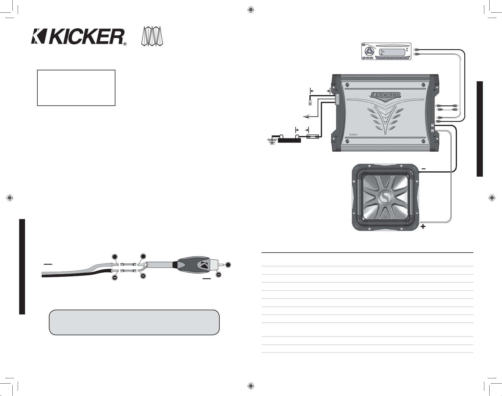
Figure 2
One Channel Operation (Mono)
Minimum impedance of 2 ohms while in bridged operation
KUNEK
10 - COMA
Source Unit
Congratulations on your
KICKER purchase!
Please record your purchase
information and keep your sales
receipt for validation of warranty.
Authorized Kicker Dealer:
Purchase Date:
Amplifi er Model Number:
Amplifi er Serial Number:
Installation
1. Mounting Choose a structurally sound location to mount your Kicker amplifi er. Make sure there
__________________________
__________________________
__________________________
__________________________
Remote
Turn-On
(45cm)
18"
Ground
(60cm)
24"
Signal Out
are no items behind the area where the screws will be driven. Choose a location that allows at least
4” (10cm) of open ventilation for the amplifi er. If possible, mount the amplifi er in the climate-controlled
passenger compartment. Drill four holes using a 7/64” (3mm) bit and use the supplied #8 screws to
Battery
+12V
Fuse
mount the amplifi er.
2. Wiring Disconnect the vehicle’s battery to avoid an electrical short. Then, connect the ground wire to
the amplifi er. Make the ground wire short, 24” (60cm) or less, and connect it to a paint and corrosion free
solid metal area of the vehicle's chassis. Adding an additional ground wire of this same gauge (or larger)
between the battery's negative post and the vehicle chassis is recommended.
The ZX amplifi er has dual input sensitivity differential RCA inputs which will receive either high or low
level signals from your car stereo’s source unit. Ideally, when connecting the source unit to the amplifi er,
the ZX amplifi er’s input level switch should be set to “LO” and a low-level signal should run from the
source unit’s stereo RCA output to the stereo RCA input on the end panel of the amplifi er using RCA
interconnect cable. If a low-level stereo RCA output is not available on the source unit, the signal can
be delivered to the amplifi er using the high-level speaker outputs on the source unit. Set the input level
switch on the end panel of the amplifi er to “HI”. Crimp and solder RCA connectors to the end of the
speaker wire running from the high-level speaker outputs on the source unit and connect the wire to the
RCA Inputs on the end panel of the amplifi er as shown in Figure 1. Either input method will provide a
low-level output signal at the RCA output, which effectively passes the audio signal to another amplifi er
or component. Keep the audio signal cable away from factory wiring harnesses and other power wiring.
If you need to cross this wiring, cross it at a 90 degree angle.
Figure 1
+
High-level Speaker Output Wire
To Source Unit
Core Cable
+
+
Model ZX400.1 ZX500.1 ZX750.1
RMS Power in Watts, all channels driven @14.4
Volts, 4Ω mono, ≤ 1% THD+N
Performance
200 x 1 250 x 1 375 x 1
@ 2Ω mono, ≤ 1% THD+N 400 x 1 500 x 1 750 x 1
Ground or Shielding
INSTALLATION
Install a fuse within 18” (45cm) of the battery and in-line with the power cable connected to your
amplifi er. If you ever need to remove the amplifi er from the vehicle after it has been installed, the ground
wire should be the last wire disconnected from the amplifi er--just the opposite as when you installed it.
See the fuse chart for power and ground wire size, and fusing recommendations.
To Amplifi er
Length: in(cm) 10 1/4 (26) 12 (30.5) 14 11/16 (37.3)
Specifi cations common to all models:
Height: in(mm) 2 1/8 (54mm)
Width: in(mm) 9 5/8 (244mm)
Frequency Response, ± 1 db: 25 Hz - 200 Hz
ModelZX400.1 1 (ONE) 40 AMPERE FUSE PowerGroundWire 4GA
ModelZX500.1 1 (ONE) 60 AMPERE FUSE PowerGroundWire 4GA
ModelZX750.1 1 (ONE) 80 AMPERE FUSE PowerGroundWire 4GA
3. Confi guration The following diagram shows the most common confi gurations for your Kicker ZX
series amplifi er.
One Channel Operation These ZX amplifi ers are capable of operating into a minimum impedance of
2 ohms. If you are using multiple voice coils, the net impedance of the voice coils must be equal to or
greater than 2 ohms.
2
ZX.1AMPLIFIER
Signal-to-Noise Ratio: >95db, a-weighted, re: rated power
Input Sensitivity:
Low Level: 125mV-5V
High Level: 250mV-10V
Variable Electronic Crossover: Variable Low-Pass, 50 - 200Hz, 24dB per octave
Subsonic Filter: 24 db/Octave Subsonic Filter Fixed @ 25Hz
Bass Boost: Variable 0-18db Bass Boost @ 40Hz
Note: To get the best performance from your new Kicker Amplifi er, we recommend using genuine Kicker Accessories and Wiring.
2008 ZX 400 500 750-1 4in1 b01.indd 3-42008 ZX 400 500 750-1 4in1 b01.indd 3-4 8/12/2008 3:25:49 PM8/12/2008 3:25:49 PM
CONFIGURATION
Signal In
3
Operation
INPUT
LEVEL
LO
HI
SPKR -
LR
INPUT
+12V
AUTO
TURN ON
DC
OFFSET
SPKR +
AUDIO
1. Automatic Turn-On Selection The ZX series offers three different automatic turn-on modes that can
be selected on the end panel; +12V, DC Offset, and Audio. Using either the DC Offset or Audio mode
causes the REM terminal to have +12V out for turning on additional amplifi ers.
Remote Turn-On Set the switch to +12V to use the remote turn-on lead from your source unit. Run
18 Ga wire from the Remote Turn-On Lead on your source unit to the terminal labeled REM between the
amplifi er’s positive and negative power terminals. This is the preferred automatic turn-on method.
DC Offset Turn-On If Remote Turn-On is not an option, the next best setting is DC Offset. The DC
Offset mode detects a 6 volt surge from the HI Level speaker outputs when the source unit has been
turned on.
Signal Sense Turn-On The Audio setting is the fi nal alternative for Automatic turn-on. This is a Signal
OPERATION
Sense turn-on method that detects the incoming audio signal from your source unit and automatically
turns on the amp. This turn-on method will not work properly if the input gain control is not set
appropriately.
2. Input Level The RCA inputs on Kicker ZX amplifi ers are capable of receiving either Hi or Low-level
signals from your source unit. If the only output available from your source unit is a Hi-Level signal, simply
press in the Input Level switch on the amplifi er. Refer to the wiring section of this manual for additional
instructions.
3. Input Gain Control The input gain control is not a volume control. It matches the output of the
source unit to the input level of the amplifi er. Turn the source unit up to about 3/4 volume (if the source
unit goes to 30, turn it to 25). Next, slowly turn (clockwise) the gain on the amplifi er up until you can hear
audible distortion, then turn it down a little.
4. Bass Boost Control The variable bass boost control on the top of the amplifi er is designed to give
you increased output 0 - 18dB at 40 Hz. The setting for this control is subjective. If you turn it up, you
must go back and adjust the input gain control to avoid clipping the amplifi er.
5. Crossover Control The variable crossover on the top of the amplifi er allows you to adjust the
crossover frequency from 50-200Hz. The setting for this control is subjective; 80Hz is a good place to
start.
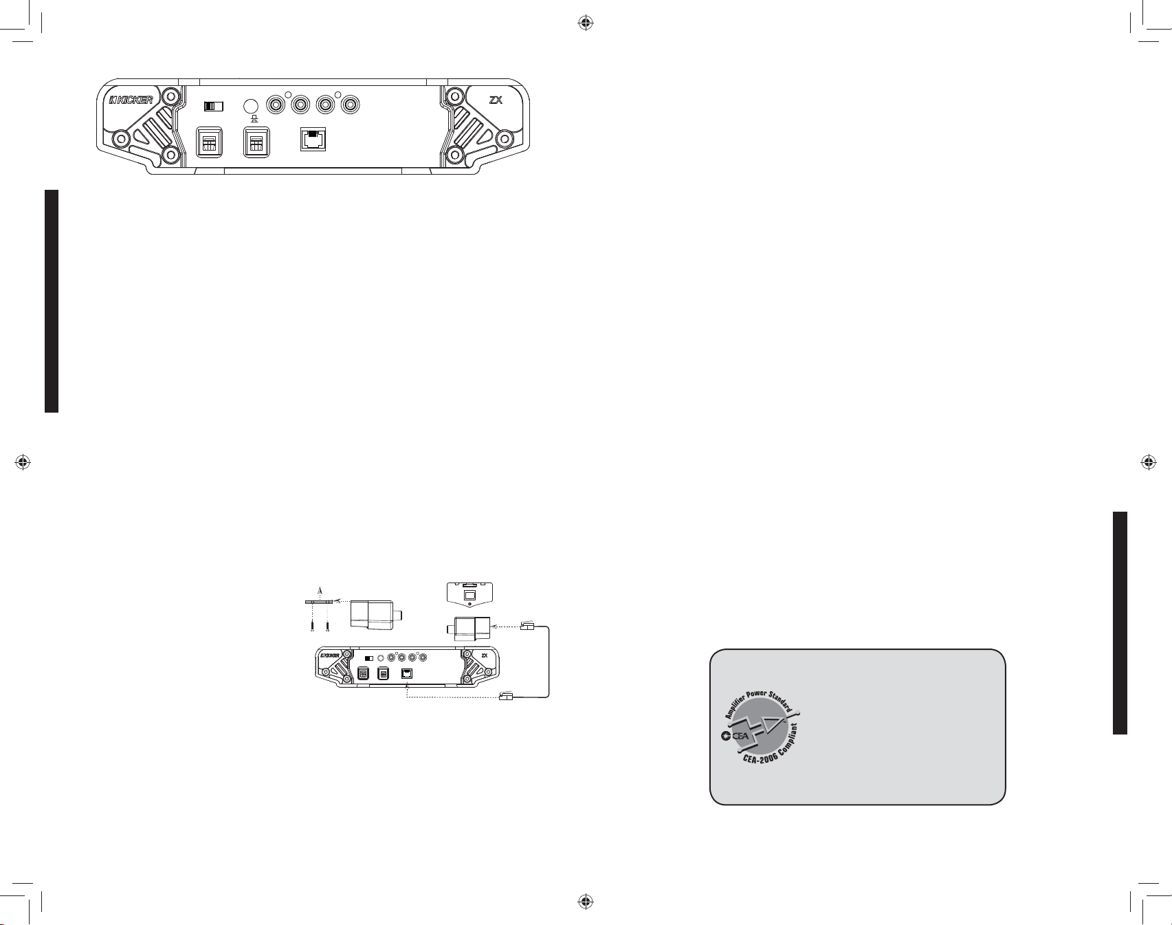
6. RemoteBass(Level Control) With the
remote bass level control, you have the ability
to control the output level of the amplifi er
remotely. To mount the remote bass level
control, simply screw the metal bracket to
the chosen location. Then slide the housing
onto the bracket until it snaps into place. Run
the cable from the controller to the “Remote
Bass” jack on the amplifi er chassis.
TroubleShooting
If your amplifi er does not appear to be working, check the obvious things fi rst such as blown fuses,
poor or incorrect wiring connections, incorrect setting of crossover switch and gain controls, etc. There
is an illuminated red badge on top of the amplifi er denoting the power state of the amp in addition to
the Protection LED on the end panel of your Kicker ZX series amplifi er. When the red badge is lit this
indicates the amplifi er is turned on and the amplifi er is functioning properly.
RED Badge Light off, no output? With a Volt Ohm Meter (VOM) check the following: 1) +12 volt
power terminal (should read +12V to +16V) 2) Remote turn-on terminal (should read +12V to +16V)
3) Check for reversed power and ground connections. 4) Ground terminal, for proper conductivity. 5)
Check for blown fuses.
LR
OUTPUT
REMOTE BASS
Mount the metal bracket
Side View
Slide the housing until it snaps into the metal bracket
L
R
AUTO
INPUT
TURN ON
LEVEL
DC
AUDIO
+12V
LO
OFFSET
INPUT
HI
REMOTE BASS
SPKR +
SPKR -
Back View
R
L
OUTPUT
4 Conductor
Phone Cable
RED Badge Light on, no output? Check the following: 1) RCA connections 2) Test speaker
outputs with a “known” good speaker. 3) Substitute source unit with a “known” good source unit. 4)
Check for a signal in the RCA cable feeding the amplifi er with the VOM meter set to measure “AC”
voltage.
End Panel LED fl ashing with loud music? The yellow LED indicates low battery voltage. Check
all the connections in your vehicle’s charging system. It may be necessary to replace or charge your
vehicle’s battery or replace your vehicle’s alternator.
End Panel LED on, no output? 1) Amplifi er is very hot. ÖThermal protection is engaged. Test
for proper impedance at the speaker terminals with a VOM meter (see the diagrams in this manual
for minimum recommended impedance and multiple speaker wiring suggestions). Also check for
adequate airfl ow around the amplifi er. 2) Amplifi er shuts down only while vehicle is running. ÖVoltage
protection circuitry is engaged. Voltage to the amplifi er is not within the 9-16 volt operating range. Have
the vehicle's charging and electrical system inspected. 3) Amplifi er will only play at low volume levels.
ÖShort circuit protection is engaged. Check for speaker wires shorted to each other or to the vehicle
chassis. Check for damaged speakers, or speaker(s) operating below the minimum recommended
impedance.
No or Low Output? 1) Check the balance and fader control on source unit 2) Check the RCA (or
speaker input) and speaker output connections.
Reduced Bass Response? Check system phasing by reversing a speaker connection from positive to
negative on the stereo/subwoofer channel(s); if the bass improves, the speaker was out of phase.
Alternator noise-whining sound with engine’s RPM? 1) Check for damaged RCA (or speaker
input) cable 2) Check the routing of RCA (or speaker input) cable 3) Check the source unit for proper
grounding 4) Check the gain settings and turn them down if they are set too high.
Ground Noise? ÖKicker amplifi ers are engineered to be fully compatible with all manufacturers’ head
units. Some head units may require additional grounding to prevent noise from entering the audio signal.
If you are experiencing this problem with your head unit, in most cases running a ground wire from the
RCA outputs on the head unit to the chassis will remedy this issue.
CAUTION: When jump starting the vehicle, be sure that connections made with jumper cables are
correct. Improper connections can result in blown amplifi er fuses as well as the failure of other critical
systems in the vehicle.
If you have more questions about the installation or operation of your new KICKER product, see the
Authorized KICKER Dealer where you made your purchase. For more advice on installation, click on
the SUPPORT tab on the Kicker homepage, www.kicker.com. Choose the TECHNICAL SUPPORT tab,
choose the subject you are interested in, and then download or view the corresponding information.
Please E-mail support@kicker.com or call Technical Services (405) 624-8583 for unanswered or specifi c
questions.
Model ZX400.1
200 x 1 @ 4 ohms, 14.4Vdc, 1% THD, CEA-2006 (Watts)
Signal to Noise Ratio -77 CEA-2006
(ref: 1W, A-weighted)
Model ZX500.1
250 x 1 @ 4 ohms, 14.4Vdc, 1% THD, CEA-2006 (Watts)
Signal to Noise Ratio -74 CEA-2006
(ref: 1W, A-weighted)
Model ZX750.1
375 x 1 @ 4 ohms, 14.4Vdc, 1% THD, CEA-2006 (Watts)
Signal to Noise Ratio -68 CEA-2006
(ref: 1W, A-weighted)
PERFORMANCE
4
2008 ZX 400 500 750-1 4in1 b01.indd 5-62008 ZX 400 500 750-1 4in1 b01.indd 5-6 8/12/2008 3:25:49 PM8/12/2008 3:25:49 PM
ZX.1AMPLIFIER
5
 Loading...