

Page 1
L5
SOLO-BARICSUBWOOFERENCLOSURE
DS12L5, DS10L5, VS12L5, TS10L5
©2007 Stillwater Designs
English Version
Versión Español
Caja de Subwoofer Solo-Baric L5
Manual del Propietario
Deutsche Version
Solo-Baric L5 Subwoofer Gehäuse
Benutzerhandbuch
Version Française
Caisson de graves Solo-Baric L5
Manuel d'utilisation
2008 L5 Box 4in1 c01.qxp 9/12/2007 7:54 PM Page 1
Page 2
CheckTheLoad
The Solo-Baric subwoofer enclosures are internally wired for a 2 or 4 ohm load at the
speaker-wire connection terminal. Please refer to this terminal or the box packaging for your
enclosure’s specific impedance. Check to see if your amplifier is optimized to drive this load.
DS/VSVented
The DS and VS Series vented enclosures combine KICKER’s award winning Solo-Baric
subwoofers with computer-modeled and human fine-tuned enclosures to offer a level of
bass performance never before thought possible from a commercially available, ready-toinstall subwoofer system. The DS Series enclosures are available with a pre-loaded pair of
10 or 12 inch Solo-Baric L5, and the VS Series has a 12 inch Solo-Baric L5.
The location and orientation of your enclosure will affect the quality and quantity of the
bass. Designed for use in SUV and sedan type vehicles, these enclosures offer you several
mounting options. The vent opening in these enclosures can not be obstructed. At some
frequencies most of the bass will come out of the vent. Therefore we recommend you leave
at least four inches (10cm) of clear space around the vent.
If the enclosure is to be mounted all the way in the back of the vehicle, it works best to
point the woofer toward the front of the vehicle. Conversely, if the enclosure is going to be
mounted closer to the back seat, pointing the woofer toward the rear of the vehicle will give
you the best results. These guidelines pertain to enclosures mounted in the vehicle as
outlined in Figure 1.
If it is more convenient to mount the enclosure along a side wall, put the enclosure on the
left side of the vehicle as outlined in Figure 2. This orientation will make the vent point
toward the rear of the vehicle and will produce the most low bass output. Remember to
leave at least four inches (10cm) of room between the enclosure and the back of the
vehicle.
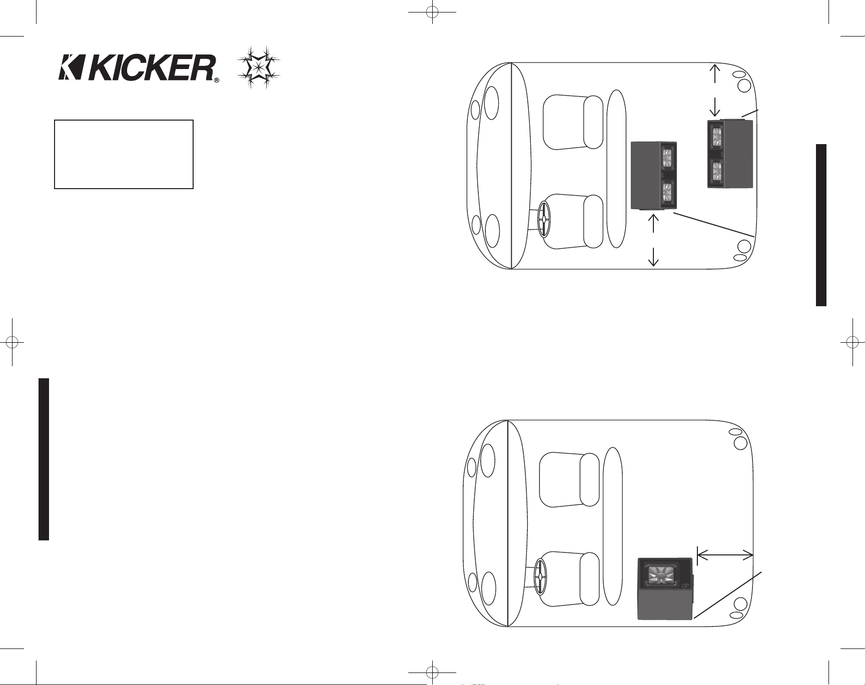
After determining the best mounting position, carefully check the areas where the mounting
brackets will be placed. Make sure the mounting screws will not puncture the gas tank,
brake lines, wiring, or interfere with any mechanical parts on the underside of the mounting
surface. Turn the enclosure upside-down, pre-drill the holes using a 7/64” (2.5mm) bit and
attach the four mounting brackets to the bottom of the enclosure using the supplied smaller
CONFIGURATION
SOLO-BARICSUBWOOFERENCLOSURE
DS12L5 /DS10L5 /VS12L5 /TS10L5
Models:
Solo-BaricL5Subwoofer
EnclosureOwner’sManual
Congratulations on your
KICKER purchase
Please record your purchase
information and keep your sales
receipt for validation of warranty.
Authorized Kicker Dealer:
Purchase Date:
Enclosure Model Number:
Enclosure Serial Number:
_________________________
_________________________
_________________________
_________________________
Please allow two weeks of break-in time for the subwoofer to reach optimum bass performance.
2 3
INSTALLATION
At least 4”
(10cm) from
the vent
Figure 2
Rear mounting,
speaker faces
front of vehicle
Front mounting,
speaker faces
rear of vehicle
Front of
Vehicle
At least 4” (10cm)
from the vent
At least 4” (10cm)
from the vent
Figure 1
screws. Each bracket must be positioned so the rounded end protrudes approximately
3/4" (2cm) from under the cabinet to allow a screw to easily pass through the bracket,
securing the enclosure to the vehicle. See Figure 4.
Plug your subwoofer speaker wire into the terminals, using the red connector as positive
and the black connector as negative. Hook the other end of the wire to your subwoofer
amplifier in accordance with its owner's manual. With the enclosure right side up, securely
attach the enclosure to the vehicle with the supplied larger screws. If the supplied hardware
is not applicable to your installation, some other means of securely attaching the enclosure
to the vehicle must be used.
Left Side
mounting,
speaker faces
opposite side
of vehicle
Front of
Vehicle
2008 L5 Box 4in1 c01.qxp 9/12/2007 7:54 PM Page 2
Page 3
4 5
PERFORMANCE
INSTALLATION
Measurements are based on the 4 ohm enclosures. Note: The use of a subsonic filter will significantly increase the power handling.
The power handling specifications in these charts are calculated using a 25Hz, 24dB per octave subsonic filter.
*Power Handling Watts RMS without subsonic filter: DS10L5-300, DS12L5-300, VS12L5-150, TS10L5-450
SOLO-BARICSUBWOOFERENCLOSURE
TSVented
The TS Series vented enclosure combines KICKER’s award winning Solo-Baric subwoofers
with computer-modeled and human fine-tuned enclosures to offer a level of bass
performance never before thought possible from a commercially available, ready-to-install
subwoofer system. The TS Series enclosure is available with a pre-loaded 10 inch
Solo-Baric L5.
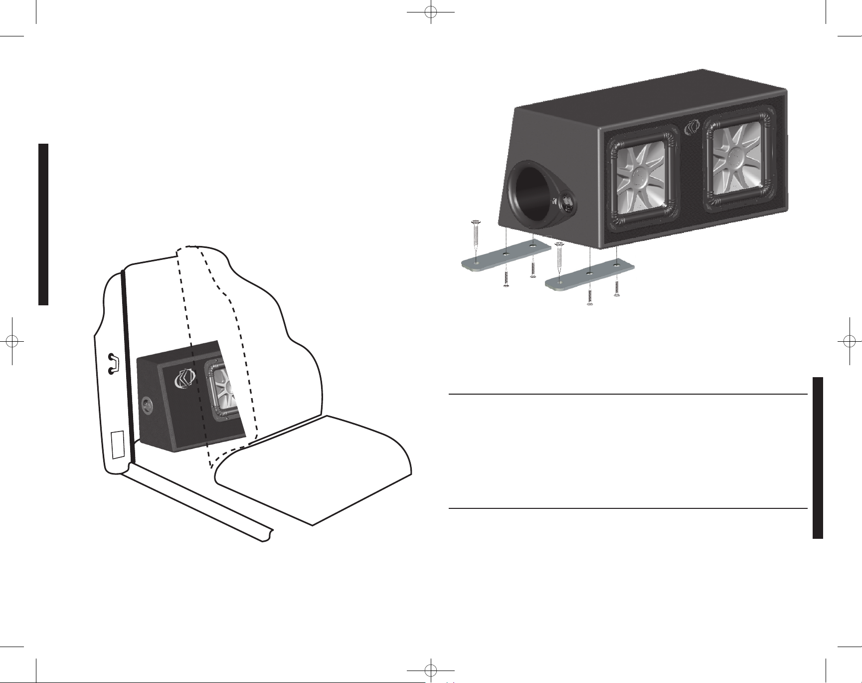
The Kicker TS Series enclosure is designed to fit behind the seat of a pickup truck, coupe
or wherever space is limited. This design is engineered to provide the best bass response
when firing into the back of the seat.
Plug your subwoofer speaker wire into the terminals, using the red connector as positive
and the black connector as negative. Hook the other end of the wire to your subwoofer
amplifier in accordance with its owner's manual.
Seat
Floor Board
Door Frame
Figure 3
Model:
Nominal Impedance [Zn], ohm [per enclosure]
Power Handling
* Watts, Peak (RMS)
Enclosure Top Surface Depth, in (cm)
Enclosure Bottom Surface Depth, in (cm)
Enclosure Height, in (cm)
Enclosure Width, in (cm)
VS12L5
2 or 4
1200 (600)
14 11/16 (37.2)
18 (45.7)
16 (40.6)
18 3/4 (47.6)
DS12L5
2 or 4
2400 (1200)
16 3/8 (41.5)
19 9/16 (49.7)
16 (40.6)
32 3/8 (82.2)
DS10L5
2 or 4
1800 (900)
15 (38.1)
18 (45.6)
14 (35.6)
28 (71.1)
TS10L5
2 or 4
900 (450)
6 11/16 (16.9)
10 (25.4)
15 (38.1)
21 1/2 (54.6)
Performance
Model:
Nominal Impedance [Zn], ohm [per enclosure]
Power Handling
* Watts, Peak (RMS)
Enclosure Top Surface Depth, in (cm)
Enclosure Bottom Surface Depth, in (cm)
Enclosure Height, in (cm)
Enclosure Width, in (cm)
Mount Brackets to the bottom of the enclosure using
the supplied smaller screws. Securely attach the
enclosure to the vehicle with the supplied larger screws.
Figure 4
SafetyWarning
To avoid potential injury, or possible death, from forward movement of the enclosure during
abrupt stops or accidents, the enclosure must be properly installed and securely fastened to
your vehicle. You are solely responsible for securely fastening the enclosure in your vehicle.
2008 L5 Box 4in1 c01.qxp 9/12/2007 7:54 PM Page 3
Page 4

6 7
VerificalosOhmios
Esta Solo-Baric caja tiene cableado interno para producir una carga de 2 ó 4 ohmios en las
terminales de conexión de cable de altavoz. Consulte la terminal o el empaque de la caja
para saber la impedancia específica de su caja. Asegúrese de que su amplificador puede
manejar esta carga.
DS/VSCajasVentiladas
Las cajas ventiladas de la serie DS y VS combinan los galardonados subwoofers Solo-Baric
de Kicker con cajas afinadas por seres humanos y diseñadas por computadora para
ofrecer un rendimiento de bajos que nunca antes se había imaginado que fuera posible
obtener de un sistema de subwoofer comercialmente disponible y listo para instalar. Las
cajas de la Serie DS vienen con un par Solo-Baric de 10 (25 cm) ó 12 plg. (30 cm)
incorporado de antemano, y de la Serie VS vienen con un Solo-Baric de 12 plg.
incorporado de antemano.
La ubicación y orientación de la caja afecta la calidad y la cantidad de los bajos. Las cajas
han sido diseñadas para vehículos tipo SUV y sedán y ofrecen varias opciones de montaje.
La abertura de ventilación de estas cajas no debe obstruirse. A ciertas frecuencias, la
mayor parte de los bajos sale por la abertura de ventilación. Por lo tanto, recomendamos
que deje por lo menos 4 plg. (10 cm) de espacio libre alrededor de la abertura de
ventilación.
Si va a montar la caja al fondo del vehículo, es mejor apuntar el woofer hacia la parte de
adelante del vehículo. Por el contrario, si va a montarla cerca del asiento de atrás, apuntar
el woofer hacia atrás produce los mejores resultados. Estas indicaciones corresponden a
las cajas montadas como se muestra en la Figura 1.
Cuando sea más conveniente montar la caja en una pared lateral, la mejor opción es
ponerla en el lado izquierdo del vehículo, como se muestra en la Figura 2. Esta orientación
hará que la abertura de ventilación apunte hacia la parte de atrás del vehículo y producirá el
mayor rendimiento de bajos. Recuerde dejar por lo menos 4 plg. (10 cm) de espacio entre
la caja y la parte atrás del vehículo.
Después de determinar la mejor posición de montaje, verifique cuidadosamente los lugares
donde van a ir los soportes de montaje. Asegúrese de que los tornillos de montaje no van a
perforar el tanque de gasolina, las líneas de freno, el cableado, etc., o a interferir con los
componentes mecánicos debajo de la superficie de montaje escogida. Invierta la caja,
taladre agujeros piloto con una broca de 7/64 de plg. (2.5 mm) y fíjele los 4 soportes de
montaje en la parte de abajo con los tornillos pequeños que se suministran.
CONFIGURACIÓN
CAJASSOLO-BARICL5
DS12L5 /DS10L5 /VS12L5 /TS10L5
Modelos:
CajadeSolo-BaricL5
ManualdelPropietario
Deje pasar aproximadamente dos semanas para que el Subwoofer logre su rendimiento óptimo de bajos.
INSTALACIÓN
Por lo menos
4 plg. (10cm)
Figura 2
Montaje atrás.
El altavoz se
orienta hacia la
parte de
adelante del
vehículo
Montaje
adelante. El
altavoz se
orienta hacia la
parte de atrás
del vehículo
Parte de
adelante
del
vehículo
Por lo menos 4 plg.
(10cm)
Po
r lo menos 4 plg.
(10cm)
Figura 1
Los soportes deben colocarse de tal manera que el extremo redondeado sobresalga
aproximadamente ¾ de plg. (2 cm) del borde de la parte de abajo de la caja para permitir
que el tornillo pase fácilmente a través del soporte y fije la caja al vehículo. Vea la Figura 4.
Enchufe el cable de altavoz del subwoofer en las terminales. Use el conector rojo como
positivo y el negro como negativo. Enchufe el otro extremo de este cable en el amplificador
del subwoofer de acuerdo con las instrucciones del manual del propietario. Con la caja
hacia arriba, fíjela firmemente al vehículo con los tornillos grandes que se suministran. Si los
tornillos que se suministran no sirven para su instalación, debe fijar firmemente la caja al
vehículo de alguna otra manera.
Montar izquierdo
de Lado, el
altavoz orientó
el lado opuesto
de vehículo
¡Felicidades por su
compra de KICKER
Por favor registre su información de compra
y mantenga su recibo de ventas para
validación de la garantía.
Distribuidor autorizado de Kicker:
Fecha de compra:
Número de modelo de la caja:
Número de serie de la caja:
_________________________
_________________________
_________________________
_________________________
Parte de
adelante
del
vehículo
2008 L5 Box 4in1 c01.qxp 9/12/2007 7:54 PM Page 4
Page 5

8 9
RENDIMIENTO
INSTALACIÓN
Las medidas se basan en modelos de 4 ohmios. Nota: El uso de un filtro subsónico aumentará significativamente el procesamiento de
potencia. Las especificaciones de procesamiento de potencia que aparecen en la tabla anterior se calculan utilizando un filtro subsónico
de 25 Hz y 24 dB/octava. Todas las especificaciones y rendimiento de las cifras están sujetos a cambios. Por favor visite www.kicker.com
para obtener la información más reciente. Para obtener el mejor rendimiento de su nuevo Subwoofer Kicker,
recomendamos usar accesorios y cableado genuinos de Kicker.
CAJASSOLO-BARICL5
TSCajasVentiladas
Las cajas ventiladas de la serie TS combinan los galardonados subwoofers Solo-Baric de
Kicker con cajas afinadas por seres humanos y diseñadas por computadora para ofrecer un
rendimiento de bajos que nunca antes se había imaginado que fuera posible obtener de un
sistema de subwoofer comercialmente disponible y listo para instalar. Las cajas de la Serie
TS vienen con un Solo-Baric de 10 plg. (25 cm) incorporado de antemano.
Las cajas TS de KICKER han sido diseñadas para ir detrás del asiento de la camioneta, el
cupé o dondequiera espacio se limita. Para dar la mejor respuesta de bajos cuando dirigen
el sonido hacia la parte de atrás del asiento del vehículo.
Enchufe el cable de altavoz del subwoofer en las terminales. Use el conector rojo como
positivo y el negro como negativo. Enchufe el otro extremo de este cable en el amplificador
del subwoofer de acuerdo con las instrucciones del manual del propietario.
Asiento
Carrocerías
Marco de
puerta
Figura 3
Modelo:
Impedancia nominal [Zn], ohmios [por caja]
Procesamiento máximo de potencia vatios, pico (RMS)
Profundidad de la superficie superior de la caja, plg. (cm)
Profundidad de la superficie inferior de la caja, plg. (cm)
Altura de la caja, plg. (cm)
Anchura de la caja, plg. (cm)
VS12L5
2 ó 4
1200 (600)
14 11/16 (37.2)
18 (45.7)
16 (40.6)
18 3/4 (47.6)
DS12L5
2 ó 4
2400 (1200)
16 3/8 (41.5)
19 9/16 (49.7)
16 (40.6)
32 3/8 (82.2)
DS10L5
2 ó 4
1800 (900)
15 (38.1)
18 (45.6)
14 (35.6)
28 (71.1)
TS10L5
2 ó 4
900 (450)
6 11/16 (16.9)
10 (25.4)
15 (38.1)
21 1/2 (54.6)
Rendimiento
Modelo:
Impedancia nominal [Zn], ohmios [por caja]
Procesamiento máximo de potencia vatios, pico (RMS)
Profundidad de la superficie superior de la caja, plg. (cm)
Profundidad de la superficie inferior de la caja, plg. (cm)
Altura de la caja, plg. (cm)
Anchura de la caja, plg. (cm)
Monte los soportes al fondo de la caja que utiliza los
tornillos más pequeños suministrados. Monte la caja al
vehículo con los tornillos más grande suministrados.
Figura 4
AdvertenciadeSeguridad
Para evitar posibles lesiones o muerte causadas por el desplazamiento hacia adelante de la
caja cuando el vehículo se detiene abruptamente o en caso de accidente, la caja debe
instalarse correctamente y fijarse firmemente al vehículo. Usted es únicamente responsable
de abrochar la caja en su vehículo.
09122007-C+08L5box
Garantía
Comuníquese con su concesionario
o distribuidor Kicker internacional
para obtener infor ación sobre
procedimientos específicos
relacionados con las normas de
garantía de su país.
2008 L5 Box 4in1 c01.qxp 9/12/2007 7:54 PM Page 5
Page 6

10 11
PrüfendieImpedanz
Das Solo-Baric Gehäuse ist intern für einen 2- oder 4-Ohm-Lastwiderstand am
Lautsprecherkabelanschluss verdrahtet. Sehen Sie bitte am Terminal oder auf der
Verpackung nach, um die spezifische Impedanz Ihres Gehäuses festzustellen. Vergewissern
Sie sich, dass Ihr Verstärker für diese Impedanz ausgelegt ist.
DS/VSBassreflexGehäuse
Bassreflexgehäuse der DS und VS-Serie kombinieren die preisgekrönten Solo-Baric
Subwoofer von KICKER mit durch Computermodelle entworfenen und von Experten
verfeinerten Gehäusen und bieten ein Bassniveau, das bisher für ein kommerziell
verfügbares, installationsbereites Subwoofer-System nicht vorstellbar war. Die Gehäuse der
DS-Serie sind mit einem bereits eingebauten paar 25 cm oder 30 cm Solo-Baric erhältlich,
und das Gehäuse der VS-Serie ist mit einem bereits eingebauten 30 cm Solo-Baric
erhältlich.
Die Position und Ausrichtung Ihres Gehäuses beeinflusst die Qualität und Quantität der
Basswiedergabe. Diese Gehäuse sind für den Einbau in Geländewagen und Limousinen
entwickelt und besitzt mehrere Einbauoptionen. Die Bassreflexöffnungen dieser Gehäuse
dürfen nicht verdeckt werden. Bei manchen Frequenzen kommt ein Großteil des Basses
aus der Öffnung. Deshalb sollten Sie mindestens 10 cm Freiraum um die Öffnung lassen.
Wenn das Gehäuse ganz hinten im Fahrzeug eingebaut wird, sollte der Tieftöner nach
vorne gerichtet sein. Wenn andererseits das Gehäuse näher am Rücksitz eingebaut wird,
erzielt man die beste Leistung, wenn der Tieftöner nach hinten gerichtet ist. Diese
Richtlinien beziehen sich auf wie in Abbildung 1 im Fahrzeug eingebaute Gehäuse.
Wenn es einfacher ist, das Gehäuse an einer Seitenwand zu montieren, sollten Sie es wie in
Abbildung 2 gezeigt auf der linken Fahrzeugseite einbauen. Diese Ausrichtung bewirkt, dass
die Bassreflexöffnung auf die Fahrzeugrückseite zeigt und die meiste Tiefbassleistung
erzeugt. Denken Sie daran, zwischen dem Gehäuse und der Rückseite des Fahrzeugs
mindestens 10 cm freizulassen.
Nachdem Sie die beste Einbauposition gewählt haben, prüfen Sie sorgfältig die Stellen, an
denen Montagehalterungen angebracht werden sollen. Vergewissern Sie sich, dass die
Montageschrauben keine Benzintanks, Bremsleitungen, Kabel usw. anbohren oder
Mechanismen an der Unterseite der Einbauoberfläche stören würden. Drehen Sie das
Gehäuse um, bohren Sie die Löcher mit einem 2,5-mm-Bohrer vor, und befestigen Sie die
vier Montagehalterungen mit den beiliegenden kleineren Schrauben an der Unterseite des
EINSTELLUNGEN
SOLO-BARICSUBWOOFERGEHÄUSE
DS12L5 /DS10L5 /VS12L5 /TS10L5
Modelle:
Solo-BaricL5Subwoofer-
GehäuseHandbuch
Nach etwa zwei Wochen erreicht der Subwoofer die optimale Bassleistung.
INSTALLATION
Mindestens
10 cm
Abbildung 2
Einbau hinten,
Lautsprecher
nach vorne
gerichtet
Einbau vorne,
Lautsprecher
nach hinten
gerichtet
Vorderseite
des
Fahrzeugs
Mindestens 10 cm
Mindestens 10 cm
Abbildung 1
Gehäuses. Jede Halterung muss so ausgerichtet werden, dass das abgerundete Ende
ungefähr 2 cm unter dem Gehäuse hervorsteht, so dass eine Schraube zur Befestigung am
Fahrzeug leicht eingeführt werden kann. Siehe Abbildung 4.
Befestigen Sie das Subwoofer-Lautsprecherkabel an den Terminals, wobei der rote
Anschluss der positive und der schwarze der negative ist. Schließen Sie das andere Ende
des Kabels am Subwoofer-Verstärker an und folgen Sie dabei dem Handbuch für den
Verstärker. Drehen Sie das Gehäuse wieder um und befestigen Sie es mit den größeren
Schrauben am Fahrzeug. Wenn die beiliegenden Befestigungselemente nicht für Ihre
Installation passen, muss eine andere Methode zur sicheren Befestigung des Gehäuses am
Fahrzeug verwendet werden.
Einbau links,
Lautsprecher
nach der
anderen
Fahrzeugseite
gerichtet
Vorderseite
des
Fahrzeugs
Herzlichen Glückwunsch zum
Kauf des KICKER
Bitte heben sie für Ihre Garantie den
Kassenzettel auf und tragen Sie die
Daten Ihres Einkaufs ein.
Authorisierter KICKER Händler:
Einkaufsdatum:
Gehäuse Modell Nummer:
Gehäuse Serien Nummer:
_________________________
_________________________
_________________________
_________________________
2008 L5 Box 4in1 c01.qxp 9/12/2007 7:54 PM Page 6
Page 7

12 13
LEISTUNG
INSTALLATION
Die Maße gelten für 4 Ohm pro Gehäuse. Die Verwendung eines Subsonic-Filters steigert die Belastbarkeit deutlich. Die Belastungswerte
in dieser Tabelle basieren auf der Verwendung eines Subsonic-Filters (25 Hz, 24 dB pro Oktave). Änderungen an Spezifikationen und
Leistungswerten vorbehalten. Sie finden die aktuellsten Informationen bei kicker.com. Anmerkung: Um die besten
Ergebnisse zu erzielen, benutzen Sie nur Originalzubehörteile und Kabel von KICKER.
SOLO-BARICSUBWOOFERGEHÄUSE
TSBassreflexGehäuse
Bassreflexgehäuse der TS-Serie kombinieren die preisgekrönten Solo-Baric Subwoofer von
KICKER mit durch Computermodelle entworfenen und von Experten verfeinerten Gehäusen
und bieten ein Bassniveau, das bisher für ein kommerziell verfügbares, installationsbereites
Subwoofer-System nicht vorstellbar war. Die Gehäuse der TS-Serie sind mit einem bereits
eingebauten 25 cm Solo-Baric erhältlich.
Kicker TS-Gehäuse passen hinter den Sitz eines Pickup-Trucks, Kabrioletts oder Coupes.
Sie sind so konzipiert, dass die beste Bassleistung erreicht wird, wenn Sie in die Rückseite
des Fahrzeugsitzes abstrahlen.
Schließen Sie die Subwoofer-Lautsprecherkabel an die Terminals an. Die roten Anschlüsse
sind positiv und die schwarzen negativ. Schließen Sie das andere Ende der Kabel am
Subwoofer-Verstärker an und folgen Sie dabei dem Handbuch für den Verstärker.
Sitzplatz
Boden
Türrahmen
Abbildung 3
Modell:
Nennimpedanz [Zn], Ohm [pro Gehäuse]
Spitzenbelastbarkeit, Watt (RMS)
Gehäuseoberflächentiefe oben, Zoll (cm)
Gehäuseoberflächentiefe unten, Zoll (cm)
Gehäusehöhe, Zoll (cm)
Gehäusebreite, Zoll (cm)
VS12L5
2 oder 4
1200 (600)
14 11/16 (37,2)
18 (45,7)
16 (40,6)
18 3/4 (47,6)
DS12L5
2 oder 4
2400 (1200)
16 3/8 (41,5)
19 9/16 (49,7)
16 (40,6)
32 3/8 (82,2)
DS10L5
2 oder 4
1800 (900)
15 (38,1)
18 (45,6)
14 (35,6)
28 (71,1)
TS10L5
2 oder 4
900 (450)
6 11/16 (16,9)
10 (25,4)
15 (38,1)
21 1/2 (54,6)
Leistung
Modell:
Nennimpedanz [Zn], Ohm [pro Gehäuse]
Spitzenbelastbarkeit, Watt (RMS)
Gehäuseoberflächentiefe oben, Zoll (cm)
Gehäuseoberflächentiefe unten, Zoll (cm)
Gehäusehöhe, Zoll (cm)
Gehäusebreite, Zoll (cm)
Befestigen Sie die Halterungen mit beiliegenden
kleineren Schrauben an beiden Seiten des Gehäuses.
Befestigen Sie dann das Gehäuse zum Fahrzeug mit
den beiliegenden größeren Schrauben.
Abbildung 4
Sicherheitswarnung
Um eine mögliche Verletzung oder Todesfolge durch eine Vorwärtsbewegung des Gehäuses
beim abrupten Anhalten oder bei Unfällen zu vermeiden, muss dieses Gehäuse korrekt
installiert und sicher an Ihrem Fahrzeug befestigt werden. Sie sind allein verantwortlich für
das Gehäuse in Ihrem Fahrzeug zu befestigen.
09102007-C+08L5box
Garantie
Nehmen Sie mit Ihren internationalen
Kicker-Fachhändler oder Vertrieb
Kontakt auf, um Details über die
Garantieleistungen in Ihrem Land zu
erfahren.
2008 L5 Box 4in1 c01.qxp 9/12/2007 7:54 PM Page 7
Page 8

14 15
VérifiezChargeCompatible
Le câblage interne du caisson en fait une charge de 2 ou 4 ohms au niveau des bornes de
raccordement des fils du haut-parleur. L'impédance de chaque caisson est indiquée sur ses
bornes ou sur son emballage. Vérifiez que cette charge est compatible avec l'amplificateur.
DS/VSÉventAccordé
Les caissons à évent accordé de la gamme DS et VS, associant les haut-parleurs
d'extrêmes graves Solo-Baric de KICKER au palmarès éloquent à des caissons modélisés
par ordinateur et accordés avec précision à l'oreille, offrent un rendu des graves auparavant
inconcevable pour un caisson de graves du commerce prêt à être installé. Les caissons DS
sont équipés d'une paire haut-parleurs Solo-Baric de 25 ou 30 centimètres pré-chargé. Les
caissons VS sont équipés d'un haut-parleur Solo-Baric de 30 centimètres pré-chargé.
L'emplacement et l'orientation du caisson affectent la qualité et l'intensité des graves.
Conçu pour une utilisation dans les véhicules de type sportif et berline, le caisson peut être
monté de plusieurs façons. L'ouverture de l'évent d'un tel caisson doit être dégagée. À
certaines fréquences, la plus grande partie des graves sort par l'évent. Il est donc conseillé
de laisser un dégagement d'au moins dix centimètres autour de l'évent.
Si le caisson est monté tout au fond du véhicule, il fonctionne mieux avec le haut-parleur
orienté vers l'avant. Inversement, si le caisson est monté près du siège arrière, les meilleurs
résultats sont obtenus avec le haut-parleur orienté vers l'arrière du véhicule. Ces
instructions concernent les caissons montés dans le véhicule conformément à la Figure 1.
S'il est plus pratique de monter le caisson sur le côté, installez-le du côté gauche du
véhicule, conformément à la Figure 2. Avec cette orientation, l'évent accordé est orienté
vers l'arrière du véhicule, ce qui permet d'obtenir le maximum d'extrêmes graves. Pensez à
laisser un espace d'au moins dix centimètres entre le caisson et l'arrière du véhicule.
Après avoir déterminé la meilleure position de montage, inspectez soigneusement les
emplacements prévus pour les pattes de montage. Vérifiez que les vis de montage ne
risquent pas de percer le réservoir d'essence, ou le câblage, ni de gêner le fonctionnement
de pièces mécaniques sous la surface de montage. Retournez le caisson, percez les trous
à l'aide d'un foret de 2,5 mm et fixez à sa base les quatre pattes de montage à l'aide des
petites vis fournies.
CONFIGURATION
CAISSONSSOLO-BARICL5
DS12L5 /DS10L5 /VS12L5 /TS10L5
Modèles :
ManuelduCaisson
deGravesSolo-BaricL5
Laissez aux caissons de graves Kicker un temps d'adaptation d'environ deux semaines pour atteindre leur niveau optimal de
performances dans les graves.
INSTALLATION
Au moins
10 cm
Figure 2
Montage arrière,
haut-parleur
orienté vers
l'avant du
véhicule
Montage avant,
haut-parleur
orienté vers
l'arrière du
véhicule
Avant
du
véhicule
Au moins 10 cm
Au moins 10 cm
Figure 1
Chaque patte doit être placée de façon à ce que son extrémité arrondie dépasse d'environ
deux centimètres du caisson afin de faciliter le vissage de la patte et la fixation du caisson
sur le véhicule. Voyez la Figure 4.
Raccordez aux bornes les fils du haut-parleur d'extrêmes graves, le fil positif à la borne
rouge et le fil négatif à la borne noire. Raccordez l'autre extrémité de chaque fil à
l'amplificateur d'extrêmes graves conformément au manuel d'utilisation de cet appareil. Le
caisson étant à l'endroit, fixez-le solidement au véhicule à l'aide des quatre grandes vis
fournies. Si les accessoires de fixation fournis ne conviennent pas pour votre installation,
fixez solidement le caisson au véhicule d'une autre façon.
Installez-le du
côté gauche
du véhicule,
haut-parleur
orienté vers
l'autre côté du
véhicule
Félicitations pour votre achat
KICKER
Prière de registrer vos informations d'achat
et de garder le ticket de caisse pour valider
votre garantie.
Distributeur Kicker agréé :
Date d'achat :
Numéro de modèle du caisson :
Numéro de série du caisson :
__________________________
__________________________
__________________________
__________________________
Avant
du
véhicule
2008 L5 Box 4in1 c01.qxp 9/12/2007 7:54 PM Page 8
Page 9

16 17
PERFORMANCES
INSTALLATION
Les valeurs sont indiquées pour des caissons de 4 ohms. Remarque : L'utilisation d'un filtre subsonique permet d'augmenter fortement la
puissance admissible. Les valeurs de puissance admissible indiquées dans ce tableau ont été calculées pour un filtre subsonique de
25 Hz à 24 dB par octave. Toutes les caractéristiques techniques et données de fonctionnement sont susceptibles de modifications sans
préavis. Pour obtenir les documents les plus récents, visitez le site kicker.com. Afin de réaliser le meilleur résultat
de votre nouveau Subwoofer Kicker, nous vous conseillons de n'utiliser que des accessoires et câblage authentiques de Kicker.
CAISSONSSOLO-BARICL5
TSÉventAccordé
Les caissons à évent accordé de la gamme TS, associant les haut-parleurs d'extrêmes
graves Solo-Baric de KICKER au palmarès éloquent à des caissons modélisés par
ordinateur et accordés avec précision à l'oreille, offrent un rendu des graves auparavant
inconcevable pour un caisson de graves du commerce prêt à être installé. Les caissons TS
sont équipés d'un haut-parleur Solo-Baric de 25 centimètres pré-chargé.
Les caissons KICKER TS ont été conçus pour être installés derrière le siège d'une
camionnette, une coupé ou où que l'espace est limité. Ils ont été étudiés de façon à offrir le
meilleur rendu de graves lorsqu'ils sont orientés vers le dossier du siège.
Raccordez aux bornes les fils du haut-parleur d'extrêmes graves, le fil positif à la borne
rouge et le fil négatif à la borne noire. Raccordez l'autre extrémité de chaque fil à
l'amplificateur d'extrêmes graves conformément au manuel d'utilisation de l'amplificateur.
Siège de
camionnette
Plancher
Montant de
porte
Figure 3
Modèle :
Impédance nominale [Zn], ohms [par caisson]
Puissance admissible, watts, crête (efficace)
Profondeur du caisson à la surface supérieure, in (cm)
Profondeur du caisson à la base, in (cm)
Hauteur du caisson, in (cm)
Largeur du caisson, in (cm)
VS12L5
2 ou 4
1200 (600)
14 11/16 (37,2)
18 (45,7)
16 (40,6)
18 3/4 (47,6)
DS12L5
2 ou 4
2400 (1200)
16 3/8 (41,5)
19 9/16 (49,7)
16 (40,6)
32 3/8 (82,2)
DS10L5
2 ou 4
1800 (900)
15 (38,1)
18 (45,6)
14 (35,6)
28 (71,1)
TS10L5
2 ou 4
900 (450)
6 11/16 (16,9)
10 (25,4)
15 (38,1)
21 1/2 (54,6)
Performances
Modèle :
Impédance nominale [Zn], ohms [par caisson]
Puissance admissible, watts, crête (efficace)
Profondeur du caisson à la surface supérieure, in (cm)
Profondeur du caisson à la base, in (cm)
Hauteur du caisson, in (cm)
Largeur du caisson, in (cm)
Obtenir les pattes de montage au fond de le caisson
utilisant les plus petites vis fournies. Attacher le caisson
au véhicule avec les plus grandes vis fournies.
Figure 4
AvertissementdeSûreté
Ce caisson doit être correctement installé et solidement fixé au véhicule afin d'éviter tout
risque de blessure, voire de mort résultant d'un déplacement du caisson vers l'avant en cas
d'arrêt brutal ou d'accident. Vous êtes uniquement responsable d'attacher le caisson dans
votre véhicule.
09122007-C+08L5box
Garantie
Pour connaître les procédures
propres à la politique de garantie
de votre pays, contactez votre
revendeur ou distributeur
International Kicker.
2008 L5 Box 4in1 c01.qxp 9/12/2007 7:54 PM Page 9
Page 10

InternationalWarranty
Contact your International Kicker dealer or distributor concerning specific procedures for your country's warranty
policies.
WARNING: KICKER products are capable of producing sound levels that can permanently damage your hearing!
Turning up a system to a level that has audible distortion is more damaging to your ears than listening to an
undistorted system at the same volume level. The threshold of pain is always an indicator that the sound level is too
loud and may permanently damage your hearing. Please use common sense when controlling volume.
GARANTÍA INTERNACIONAL VersiónEspañol
Comuníquese con su concesionario o distribuidor Kicker internacional para obtener infor ación sobre procedimientos
específicos relacionados con las normas de garantía de su país.
ADVERTENCIA: Los excitadores Kicker son capaces de producir niveles de sonido que pueden dañar
permanentemente el oído. Subir el volumen del sistema hasta un nivel que produzca distorsión es más dañino para el
oído que escuchar un sistema sin distorsión al mismo volumen. El dolor es siempre una indicación de que el sonido es
muy fuerte y que puede dañar permanentemente el oído. Sea precavido cuando controle el volumen.
La frase "combustible para vivir la vida Livin' Loud™ a todo volumen" se refiere al entusiasmo por la vida que la marca
Kicker de estéreos de automóvil representa y a la recomendación a nuestros clientes de que vivan lo mejor posible ("a
todo volumen") en todo sentido. La línea de altavoces y amplificadores Kicker es la mejor del mercado de audio de
automóviles y por lo tanto representa el "combustible" para vivir a todo volumen en el área de "estéreos de automóvil"
de la vida de nuestros clientes. Recomendamos a todos nuestros clientes que obedezcan todas las reglas y
reglamentos locales sobre ruido en cuanto a los niveles legales y apropiados de audición fuera del vehículo.
INTERNATIONALE GARANTIE DeutscheVersion
Nehmen Sie mit Ihren internationalen Kicker-Fachhändler oder Vertrieb Kontakt auf, um Details über die
Garantieleistungen in Ihrem Land zu erfahren.
WARNUNG: KICKER-Treiber können einen Schallpegel erzeugen, der zu permanenten Gehörschäden führen kann!
Wenn Sie ein System auf einen Pegel stellen, der hörbare Verzerrungen erzeugt, schadet das Ihren Ohren mehr, als ein
nicht verzerrtes System auf dem gleichen Lautstärkepegel. Die Schmerzschwelle ist immer eine Anzeige dafür, dass
der Schallpegel zu laut ist und zu permanenten Gehörschäden führen kann. Seien Sie bei der Lautstärkeeinstellung
bitte vernünftig!
Der Slogan "Treibstoff für Livin' Loud" bezieht sich auf die mit den Kicker-Autostereosystemen assoziierte
Lebensfreude und die Tatsache, dass wir unsere Kunden ermutigen, in allen Aspekten ihres Lebens nach dem Besten
("Livin' Loud") zu streben. Die Lautsprecher und Verstärker von Kicker sind auf dem Markt für Auto-Soundsysteme
führend und stellen somit den "Treibstoff" für das Autostereoerlebnis unserer Kunden dar. Wir empfehlen allen unseren
Kunden, sich bezüglich der zugelassenen und passenden Lautstärkepegel außerhalb des Autos an die örtlichen
Lärmvorschriften zu halten.
GARANTIE INTERNATIONALE VersionFrançaise
Pour connaître les procédures propres à la politique de garantie de votre pays, contactez votre revendeur ou
distributeur International Kicker.
AVERTISSEMENT: Les haut-parleurs Kicker ont la capacité de produire des niveaux sonores pouvant endommager
l'ouïe de façon irréversible ! L'augmentation du volume d'un système jusqu'à un niveau présentant une distorsion
audible endommage davantage l'ouïe que l'écoute d'un système sans distorsion au même volume. Le seuil de la
douleur est toujours le signe que le niveau sonore est trop élevé et risque d'endommager l'ouïe de façon irréversible.
Réglez le volume en faisant prevue de bon sens !
L'expression " carburant pour vivre plein pot " fait référence au dynamisme de la marque Kicker d'équipements audio
pour véhicules et a pour but d'encourager nos clients à faire le maximum (" vivre plein pot ") dans tous les aspects de
leur vie. Les haut-parleurs et amplificateurs Kicker sont les meilleurs dans le domaine des équipements audio et
représentent donc pour nos client le " carburant pour vivre plein pot " dans l'aspect " installation audio de véhicule "
de leur vie. Nous encourageons tous nos clients à respecter toutes les lois et réglementations locales relatives aux
niveaux sonores acceptables à l'extérieur des véhicules.
SOLO-BARICSUBWOOFERENCLOSURE
GARANTIE
WARRANTY
09122007-C+08L5box
Note: All specifications and performance figures are subject to change. Please visit the www.kicker.com for the most current information.
To get the best performance from your new Kicker Subwoofer, we recommend using genuine Kicker Accessories and Wiring.
18 19
AcousticsLimitedWarranty
Kicker warrants this product to be free from defects in material and workmanship under normal use for a period of
THREE (3) MONTHS from date of original purchase with receipt. When purchased from an Authorized KICKER Dealer
it is warranted for ONE (1) YEAR from date of original purchase with receipt. In all cases you must have the original
receipt. Should service be necessary under this warranty for any reason due to manufacturing defect or malfunction
during the warranty period, Kicker will repair or replace (at its discretion) the defective merchandise with equivalent
merchandise at no charge. Warranty replacements may have cosmetic scratches and blemishes. Discontinued
products may be replaced with more current equivalent products.
This warranty is valid only for the original purchaser and is not extended to owners of the product subsequent to the
original purchaser. Any applicable implied warranties are limited in duration to a period of the express warranty as
provided herein beginning with the date of the original purchase at retail, and no warranties, whether express or
implied, shall apply to this product thereafter. Some states do not allow limitations on implied warranties; therefore
these exclusions may not apply to you. This warranty gives you specific legal rights; however you may have other
rights that vary from state to state.
WHAT TO DO IF YOU NEED WARRANTY OR SERVICE
Defective merchandise should be returned to your local Authorized Stillwater Designs (Kicker) Dealer for warranty
service. Assistance in locating an Authorized Dealer can be found at www.kicker.com or by contacting Stillwater
Designs directly. You can confirm that a dealer is authorized by asking to see a current authorized dealer window
decal.
If it becomes necessary for you to return defective merchandise directly to Stillwater Designs (Kicker), call the Kicker
Customer Service Department at (405) 624-8510 for a Return Merchandise Authorization (RMA) number. Package only
the defective items in a package that will prevent shipping damage, and return to:
Stillwater Designs, 5021 North Perkins Road, Stillwater, OK 74075
The RMA number must be clearly marked on the outside of the package. Please return only defective components.
The return of functioning items increases your return freight charges. Non-defective items will be returned freightcollect to you. For example, if a subwoofer is defective, only return the defective subwoofer, not the entire enclosure.
Include a copy of the original receipt with the purchase date clearly visible, and a "proof-of-purchase" statement listing
the Customer's name, Dealer's name and invoice number, and product purchased. Warranty expiration on items
without proof-of-purchase will be determined from the type of sale and manufacturing date code. Freight must be
prepaid; items sent freight-collect, or COD, will be refused.
WHAT IS NOT COVERED?
This warranty is valid only if the product is used for the purpose for which it was designed.
It does not cover:
o Damage due to improper installation
o Subsequent damage to other components
o Damage caused by exposure to moisture, excessive heat, chemical cleaners, and/or UV radiation
o Damage through negligence, misuse, accident or abuse. Repeated returns for the same damage may be
considered abuse
o Any cost or expense related to the removal or reinstallation of product
o Speakers damaged due to amplifier clipping or distortion
o Items previously repaired or modified by any unauthorized repair facility
o Return shipping on non-defective items
o Products with tampered or missing barcode labels
o Products returned without a Return Merchandise Authorization (RMA) number
o Freight Damage
o The cost of shipping product to Kicker
o Service performed by anyone other than Kicker
HOW LONG WILL IT TAKE?
Kicker strives to maintain a goal of 24-hour service for all acoustics (subwoofers, midrange and coaxial drivers,
tweeters, crossovers, etc) returns. Delays may be incurred if lack of replacement inventory or parts is encountered.
Failure to follow these steps may void your warranty. Any questions can be directed to the Kicker Customer Service
Department at (405) 624-8510.
P.O. Box 459 • Stillwater, Oklahoma 74076 • U.S.A. • (405) 624-8510
2008 L5 Box 4in1 c01.qxp 9/12/2007 7:54 PM Page 10
 Loading...