


Features
Hemispherical Polymineral Cone with Inverted Structural Dome™
(ISD) means high rigidity under pressure for accurate linear control, low enclo-
sure pressure loss to reduce "pump-down", high internal dampening, and excellent sunlight, pollution and moisture resistance.
Double-Stitched Surround prevents cone/surround separation at
high excursions.
Blackened Pole Piece maximizes heat transfer for long voice coil life.
Extended Pole Piece allows cooler operation for superior power handling
and magnetic field linearity around voice coil gap for enhanced control.
Vented Pole Piece relieves low bass-robbing pressure under the center
dome.
Extended Backplate prevents damaging voice coil "bottoming".
Perimeter Venting for measurably lower operating temperature and freer
cone motion.
Hi-Temp Kapton® Voice Coil Former protects against warped, rubbing
voice coils.
Long-Throw Voice Coil for enormous cone excursion capabilities.
High Power Lead Wires resist lead breakage and reduce power robbing
resistance losses.
C8VR/C10VR/C12VR/C15/C18VR
Subwoofers
Congratulations! You have just purchased one of the most flexible subwoofers yet
from KICKER. Your CompVR sub is designed to give you great bass performance in a
wide variety of applications. These installations instructions will help you get the most
out of your new KICKER sub. Thanks for buying KICKER. Enjoy!

Installation Instructions
The Comp subs are designed to be as universal as possible. Great performance
can be obtained when using them in sealed or vented boxes as well as on an
Infinite Baffle (freeair).
Infinite Baffle Mounting
The infinite baffle or freeair mounting method is very effective in a sedan type
of vehicle. The easiest way to do this is to cut out the parcel shelf just big
enough for your chosen driver(s). The parcel shelf is usually not very strong and
any flexing will decrease the bass response. To reinforce this area and to give you
something to mount the woofer(s) to, a piece of strong wood needs to be cut
and mounted to the bottom of the shelf. We recommend a medium to high
density fiberboard (MDF or HDF) 3/4" thick. Common particle board is not very
good for use in a car stereo. If a good grade of fiberboard is not available in your
area, use a good grade of marine plywood.
The key factor in utilizing the freeair method is to make sure the information
coming off the back of the woofer doesn't have a chance to mix with the information coming off the front. If the front and back are not sealed from each
other a big part of the bass will get cancelled out.
2
3
Sealed box mounting
A very smooth bass response with good low bass extension is achieved when
the Kicker Comp woofers are mounted in a correctly built sealed box with the
correct airspace. Sealed (acoustic suspension) designs have been a favorite here
at Kicker since the original Competition Series was introduced. We build just
about all of our show vehicles with sealed boxes for the smooth response, good
power handling and great sound quality they offer.
Of all the enclosures possible the sealed box is the easiest to build. The two
most important rules are to make it very solid and to seal all the joints perfectly.
If the panels of an enclosure can flex or vibrate you will experience a loss of bass
output. You don't want to throw away any of the output capability of your
Kicker Comp woofers. Sealing all the joints in the enclosure is necessary to avoid
loss of output and driver failure.
The following information will give you examples of compact sealed enclosures
for the Kicker Comp woofers. They have very high power handling and massive
amounts of high impact bass. The given volumes are the minimum recommended and include driver displacement. Maximum volumes for KICKER Comps are
C8-1.2cf, C10-2.4 cf., C12-3.5 cf., and C15-5.0 cf. As the sealed enclosure volumes increase, the response will shift from high impact bass to a smoother and
more extended low end.
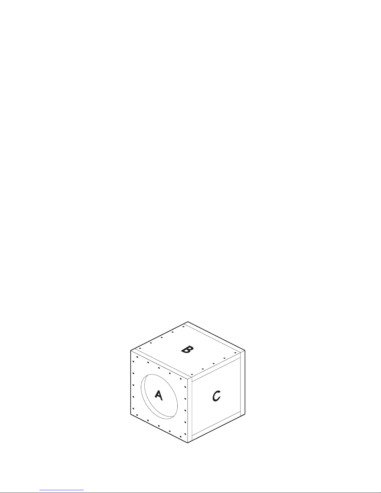
Compact
Model Enclosure Woofer A B C
Volume Cutout panel panel panel
C8VR .5 cf 7” 11 x 11” 11 x 9-1/2” 9-1/2 x 9-1/2”
C10VR 1.0 cf 9-5/32" 13-1/2x13-1/2" 13-1/2x12" 12x12"
C12VR 1.25 cf 10-15/16" 14-1/2x14-1/2" 14-1/2x13" 13x13"
C15VR 2.25 cf 13-11/16" 17-1/4x17-1/4" 17-1/4x15-3/4" 15-3/4x15-3/4"
C18VR 2.75 cf 16-5/16" 19-1/2x19-1/2" 19-1/2x14-1/2" 14-1/2x18"

4
Vented Box Mounting
Almost as easy to build as the sealed box, the vented or ported enclosure can
give you more output at certain bass frequencies. Although this design has an
output advantage at some frequencies it also has a sharper rolloff characteristic
which will only affect the lowest of bass frequencies. Overall a correctly designed
vented enclosure will have some "free" output provided by the port itself.
One major disadvantage to the vented design is the "unloading" of the woofer
at very low frequencies. At a frequency 1/2-octave below the tuning frequency
of the enclosure the woofer acts like it has no box to work in and can go to full
excursion. This will be harmful to the woofer's mechanical integrity. It is therefore very important to stay with the recommended designs.
Since the peak pressure inside a vented enclosure can actually be higher than
that of a sealed box, the same precautions must be taken to assure that the
enclosure is rigid and sealed around all the joints.
Recommended vented enclosure volume ranges are .8-1.2cf for the C8, 1.25-
1.75 cf for the C10, 1.75-2.25 cf for the C12, and 3.0-4.0 cf for the C15. As with
the sealed boxes, as enclosure volume increases the response shifts from high
impact to a smoother and more extended bass sound.
Below are specifications for a simple compact vented box for each sub.
Compact Enclosure SPL/Deep Bass
Model (Minimum) Vented (Maximum) Vented
Volume Volume
CompVR 8 .8 cu.ft + port 1.20 cu.ft. + port
port 1-1/2 x 8 x 20” port 2 x 8 x 18-3/8”
Power Handling = 75W Power Handling = 75W
CompVR 10 1.25 cu.ft. + port 1.75 cu.ft. + port
Port 2 x 10⁻¹/2 x 20” Port 2-1/2 x 10-1/2 x 20”
Power Handling = 150 Power Handling = 150
CompVR 12 1.75 cu.ft. + port 2.25 cu.ft. + port
Port 2-1/2 x 12-1/2 x 20” Port 3 x 12-1/2 x 20-1/2”
Power Handling = 150 Power Handling = 150
CompVR 15 3 cu.ft. + port 5 cu.ft. + port
Port 2-3/4 x 15-1/2 x 25-3/4” Port 3 x 15-1/2 x 22”
Power Handling = 500 Power Handling = 500
CompVR 18
4.0 cu..ft.. + port 6 cu..ft.. + port
Port 3 x 18 x 24-1/4” Port 3 x 18 x 20-3/4”
Power Handling = 500 Power Handling = 500

5
Multiple Woofer Enclosures
If you are building enclosures for more than one woofer, they should always
be divided to maintain the correct airspace for each woofer. There are a couple
of reasons for this. First of all, not all woofers are exactly the same. If there are
slight differences between the woofers in a common enclosure, at certain frequencies one woofer may think it's in a larger enclosure than intended. This can
affect the power handling capability. Second, if one woofer fails, the remaining
woofers will have more airspace to work in than what was designed. Again, this
will severely affect the power handling capability of the woofers that are still
working.
Another benefit of a divided enclosure is that the divider helps strengthen the
enclosure. A large common enclosure will have much bigger panels than one
that is divided. Large panels tend to flex more and can cancel some of the
woofer's output.

6
Box Building Tips
The material of choice for building a strong box is 3/4" MDF (Medium
Density Fiberboard). Cross bracing is a good idea to help reduce panel vibration.
Strips of 3/4" by 2" wood work well for tying the panels together. HDF (High
Density Fiberboard) is also good as is a really good grade of plywood (such as
marine grade 7 or 13 ply). Regular particle board is not very good for speaker
enclosures. It is flexible and will crumble when you try to screw the woofer in.
A good grade of wood glue is recommended for joining two pieces of wood
together along with 1-1/4 to 1 1/2" drywall screws or 1-1/2" staples. A fastener
placed about every 3" will hold the box together good enough until the glue
dries. After assembling the box and allowing the glue to set up, use silicone sealer to make absolutely sure the corners are perfectly sealed.
Hint: When assembling the enclosure, build the whole enclosure except for
the rear baffle opposite the woofer cutout. This way you can easily reach inside
to apply the silicone sealer. Once this is done, put the rear panel on and seal it by
reaching through the woofer cutout.
A common source of air leaks is the connecting wire for the woofers. Terminal
cups are commonly available and are recommended. They provide an airtight
means for bringing the wire into the enclosure and allow for easy wiring
changes. An alternative is to drill a hole slightly larger than the wire and seal
carefully with silicone sealer. Do not disturb the silicone until it has set up.
Moving the wire before the silicone has set up will usually cause an air leak.
If you carpet the enclosure it is important to cut the carpet around the woofer
opening. It is hard to get a good seal if you have both the gasket and the carpet
between the woofer and the wood.
On a sealed enclosure it is easy to test the seal of the box. Push the cone in all
the way and let it go. If the seal is good, the cone should take at least five seconds to return to the center position. If the cone spring back faster that that
you have a leak somewhere in the enclosure. Sometimes you can hear air escaping around the woofer or at one of the joints in the enclosure. If the box itself
leaks take the woofer out and check the silicone seal all around the inside. If the
air is leaking out around the woofer try adding a flexible sealer like plumber's
putty or rope caulk. Don't use silicone sealers around the woofer.
For more information and additional box plans, see the KICKER Comp Technical
Brief on kicker.com or call the Technical Services Line at (405)624-8583.

Specifications
Model C8VR C10VR C12VR C15VR C18VR
SPL 1W/1M 83.0dB 85.6dB 86.4dB 88.5dB 89.1dB
Displacement, cc 673.5 982.3 2001.2 3992.6 6513.39
Displacement, cu in 41.1 75.3 122.1 243.6 397.4
Hole cutout, in. dia. 7 9-5/32 10-15/16 13-3/4 16-5/16
Mounting Depth, in. 3-15/16 5-7/16 6 7-1/2 8-1/4
Revc 7.58 Ohms 7.75 Ohms 7.81 Ohms 7.18 Ohms 7.32 Ohms
Sd, SqM ,0214 .0379 .05321 .0881 0.1159
BL, TM 11.79 17.65 18.3 19.78 26.83
Vas, Liters 14.11 40.40 92.82 257.3 423.17
Vas, CuFt. .498 1.42 3.28 9.08 14.94
Mms, gms 60.17 116.29 151.47 227.92 372.63
Fs, Hz 44.1 33.1 26.8 21.8 17.5
Qms 9.34 8.703 9.38 10.689 11.942
Qes .908 .603 .596 .573 0.417
Qts .828 .564 .561 .544 0.403
Pmax, watts 200 300 400 500 1000
Xmax, mm 8.5 11.5 11.5 12.75 14
Freq Response, Hz 30-500 25-500 25-500 25-500 23-500
Magnet weight, oz 25 43 45 100 138
Voice coil (Kapton), In. 1-1/2 2 2 2 2-1/2
*Based on 4-Ohm models
7

• Install slips (screwdriver holes)
• Damage caused by exposure to water
and/or excessive heat.
• Damage through negligence, misuse, or
accident.
• Items physically damaged due to abuse.
• Freight damage.
• The cost of shipping product to Stillwater
Designs Service.
HOW LONG WILL IT TAKE?
Stillwater Designs maintains a goal of 24-hour service for all returns. Delays may be
incurred if lack of replacement inventory or parts is encountered.
INTERNATIONAL WARRANTY
Contact your International Stillwater Designs dealer or distributor concerning specific
procedures for your country’s warranty policies.
P.O. Box 459 • Stillwater, Oklahoma 74076 • U.S.A. • 405 624-8510
• Items previously repaired by any
unauthorized repair facility.
• Items returned from unauthorized
individuals or dealers.
• Return shipping on non-defective items.
• Speakers damaged due to amplifier
clipping or distortion.
• Speakers with silicon caulk used for gasket
material.
KICKER drivers are capable of producing sound levels that can permanently
damage your hearing! Turning up a system to a level that has audible distortion is more damaging to your ears than listening to an undistorted system at
the same volume level. The threshold of pain is always an indicator that the
sound level is too loud and may permanently damage your hearing.
PPleaase use common sense when controlling volume!!
WARNING:
SPEAKER SYSTEMS LIMITED WARRANTY
Stillwater Designs warrants this product to be free from defects in material and workmanship under
normal use for a period of one (1) year from date of original purchase from an authorized
Kicker Dealer, unless this product is labeled “B Stock”, in which case it is warranted for ninety (90) days
from date of purchase. Should service be necessary under this warranty for any reason due to manufacturing defect or malfunction during the warranty period, Stillwater Designs will replace or repair (at its
discretion) the defective merchandise with equivalent merchandise at no charge. Warranty replacements
on “B-Stock” may have cosmetic scratches and blemishes. Discontinued products may be replaced with
equivalent products.
This warranty is valid only for the original purchaser and is not extended to owners of the product
subsequent to the original purchaser. Any applicable implied warranties are limited in duration to a period
of the express warranty as provided herein beginning with the date of the original purchase at retail, and
no warranties, whether express or implied, shall apply to this product thereafter. Some states do not
allow limitations on implied warranties, therefore these exclusions may not apply to you.
This warranty gives you specific legal rights; however you may have other rights that vary from state to
state.
WHAT TO DO IF YOU NEED WARRANTY OR SERVICE
Defective merchandise must be returned to your local Authorized Stillwater Designs (Kicker) Dealer for
warranty. Assistance in locating an Authorized Dealer can be obtained by writing or calling Stillwater
Designs direct. You can confirm that a dealer is authorized by asking to see a current authorized dealer
window decal.
If it becomes necessary for you to return defective merchandise, call the Kicker Customer Service
Department at (405)624-8510 for a Return Authorization (RA) number. Package all defective items in the
original container or in a package that will prevent shipping damage, and return to
Stillwater Designs, 5021 North Perkins Road, Stillwater, OK 74075
The RA number must be clearly marked on the outside of the package. Return only defective components. Return of entire cabinets, system packs, pairs, etc. increases your return freight charges. Nondefective items received will be returned freight collect.
Include a dated proof-of-purchase from an Authorized Dealer. Warranty expiration on items
returned without proof-of-purchase will be determined from the manufacturing date code. Coverage
may be invalidated if this date is greater than 18 months previous to the date item is sent in. Freight
must be prepaid; items received freight collect will be refused.
Failure to follow these steps may void your warranty. Any questions can be directed to the Kicker
Customer Service Department at (405)624-8510.
WHAT IS NOT COVERED?
This warranty is valid only if the product is used for the purpose for which it was designed.
It does not cover:
March 2002
 Loading...