

Page 1
Page 2
COMPSUBWOOFER
Enc/osureOwner'sManua/
Models:
Congratulations on your
KICKER purchase
Please record your purchase
information and keep your sales
receipt for validation
The Kicker Comp subwoofer enclosures were specially designed for "Livin' Loud" out
automotive environment. They are made
maintain optimal performance for yearstocome.
of
warranty.
Authorized Kicker Dealer:
Purchase Date:
Enclosure Model Number:
Enclosure Serial Number:
of
advanced materials and construction techniques
OC12/
OC10 / VC12 / TC10
in
the harsh
CheckTheLoad
The Comp subwoofer enclosures are internally wired for a 2 or 4 ohm load at the speaker-wire
to
connection terminal. Please refer
to
impedance. Check
see if your amplifierisoptimizedtodrive this load.
this terminal or the box packaging for your enclosure's specific
to
DCIVC
The
DCNC
computer-modeled and human fine-tuned enclosures
thought possible from a commercially available, ready-to-install subwoofer system. The DC Series
enclosures are available with a pair of pre-loaded 10 or 12 inch Comp subwoofers. The VC Series
enclosure
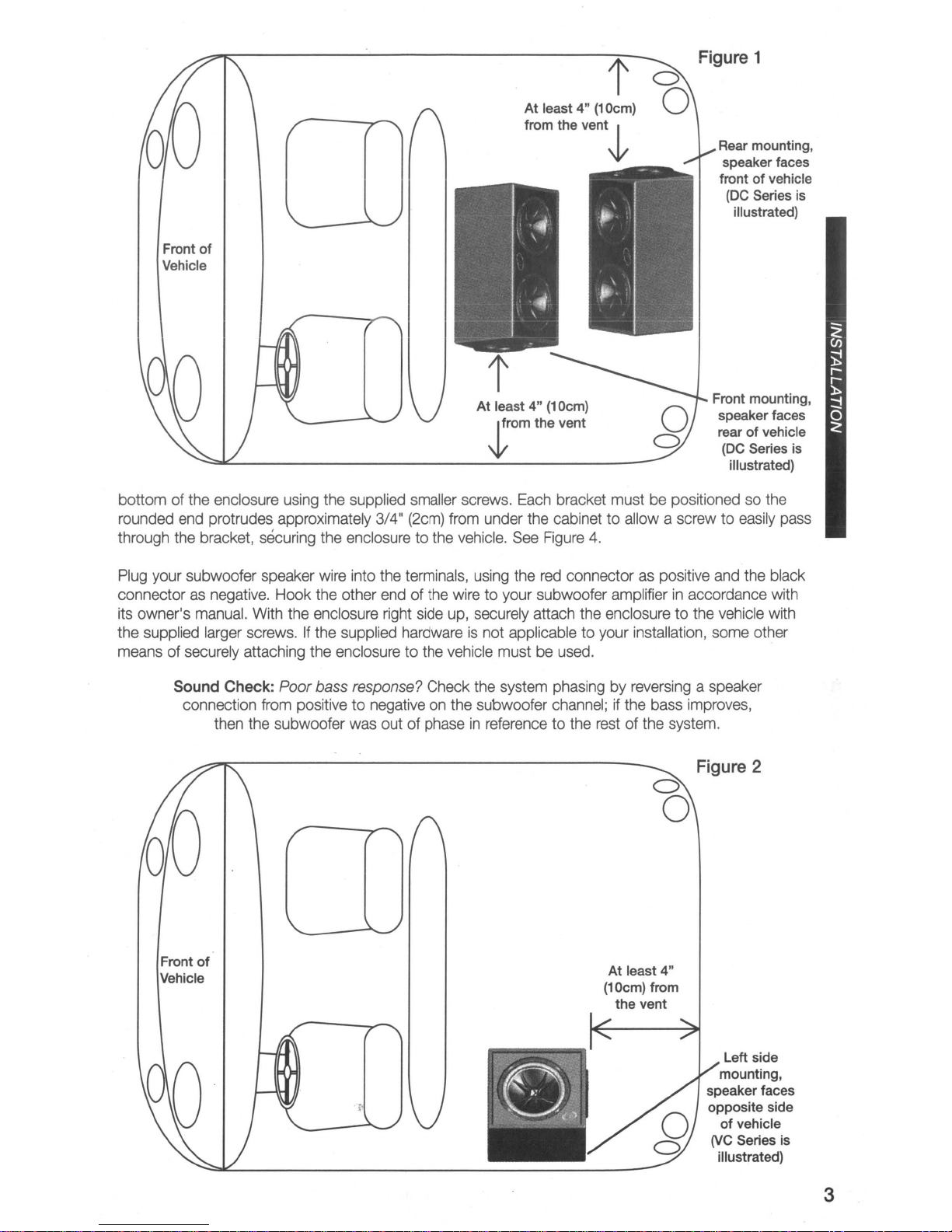
The location and orientation of your enclosure will affect the quality and quantity of the bass. Designed
for use
• opening
out of the vent. Therefore we recommend you leave at least four inches (10cm) of clear space around
the vent.
If the enclosure
woofer toward the front of the vehicle. Conversely, if the enclosure
back seat, pointing the woofer toward the rear of the vehicle will give you the best results. These
guidelines pertain
Ifitis
the vehicle
vehicle and will produce the most low bass output. Remember to leave at least four inches (10cm)
room between the enclosure and the back of the vehicle.
Series vented enclosures combine KICKER's award winning line of subwoofers with
is
available with a pre-loaded 12 inch
in
SUV and sedan type vehicles, these enclosures offer you several mounting options. The vent
in
these enclosures can not be obstructed. At some frequencies mostofthe bass will come
more convenienttomount the enclosure along a side wall, put the enclosure on the left side of
as
Ven
ted
to
offer a level of bass performance never before
Compo
is
to be mounted
to
enclosures mountedinthe vehicle as outlinedinFigure 1.
outlinedinFigure2.This orientation will make the vent point toward the rearofthe
all
the wayinthe back of the vehicle, it works besttopoint the
is
goingtobe mounted closertothe
of
After determining the best mounting position, carefully check the areas where the mounting brackets
will be placed. Make sure the mounting screws will not puncture the gas tank, brake lines, wiring, or
interfere with any mechanical parts on the underside of the mounting surface. Turn the enclosure
upside-down, pre-drill the holes using a 7/64" (2.5mm) bit and attach the four mounting brackets
Please allow
2
two
weeksofbreak-in time for the subwoofer to reach optimum performance.Toget the best performance
from your new Kicker subwoofers, we recommend using genuine Kicker Accessories and Wiring.
COMPSUBWOOFERENCLOSURE
to
the
Page 3
Front
Vehicle
of
t
At least4"(10cm)
from the
vent~
Figure 1
Rear mounting,
speaker faces
front of vehicle
(DC
Series is
illustrated)
At least 4" (10cm)
Jrom
bottom of the enclosure using the supplied smaller screws. Each bracket must be positioned so the
rounded end protrudes approximately 3/4" (2cm) from under the cabinet to allow a screw to easily pass
to
through the bracket, securing the enclosure
Plug your subwoofer speaker wire into the terminals, using the red connector as positive and the black
connector as negative. Hook the other end of the wire to your subwoofer amplifier
its owner's manual. With the enclosure right side up, securely attach the enclosure
If
the supplied larger screws.
means of securely attaching the enclosure to the vehicle must be used.
Sound
Check:
connection from positive to negative on the subwoofer channel; if the bass improves,
then the subwoofer was out of phase
the supplied hardwareisnot applicable to your installation, some other
Poor
bass
response?
the vehicle. See Figure
Check the system phasing by reversing a speaker
in
referencetothe restofthe system.
the vent
4.
Front mounting,
speaker faces
rear
of
(DC
Series is
illustrated)
in
accordance with
to
the vehicle with
vehicle
Figure 2
a
o
Front
of
Vehicle
At least 4"
(10cm) from
the vent
Left side
mounting,
speaker faces
opposite side
of
vehicle
rJC Series is
illustrated)
3
Page 4

TCVented
The TC Series vented enclosure combines KICKER's award winning line of subwoofers with computer-
of
modeled and human fine-tuned enclosures to offer a level
possible from a commercially available, ready-to-install subwoofer system. The TC Series enclosure
available with a pre-loaded 10 inch
The Kicker TC Series enclosureisdesigned to fit behind the seat of a pickup truck, coupe or wherever
is
space
of the seat. The vent opening
bass will come out of the vent. Therefore we recommend you leave at least four inches (10cm) of clear
space around the vent.
Plug your subwoofer speaker wire into the terminals, using the red connector as positive and the black
connector as negative. Hook the other end of the wire
• its owner's manual.
limited. This designisengineered to provide the best bass response when firing into the back
Compo
in
this enclosure can not be obstructed. At some frequencies most of the
bass performance never before thought
to
your subwoofer amplifierinaccordance with
Pro
Tip:
You
Amplifier
from
Kicker
and
a slammJin system!
ZX
lineofmono-amplifiers
are one
a few cables away
ZX
make it easy to upgrade to rocksolid bass with your existing
stock source unit. Please ask
your dealer about the Kicker
Amplifier upgrades.
is
Mono-
The
or
ZX
Behind the seat
mounting, speaker
fires into the back
of
the seat
(TC Series
illustrated)
is
/
Figure 3
SafefyWarning
To
avoid potential
stops or accidents, the enclosure must be properly installed and securely fastened to your vehicle.
are solely responsible for securely fastening the enclosureinyour vehicle.
injury,orpossible death, from forward movementofthe enclosure during abrupt
4
You
COMPSUBWOOFERENCLOSURE
Page 5

Figure 4
Performance
Model:
Nominal Impedance
Sensitivity [SPLo], dB
Power Handling Watts, Peak
Enclosure Top Surface Depth,in(cm)
Enclosure Bottom Surface Depth,in(cm)
Enclosure Height,in(cm)
Enclosure Width,in(cm)
Model:
Nominal Impedance
[Zn],
ohm [per enclosure]
@
1W,
1m
(RMS)
[Zn],
ohm [per enclosure]
Mount Bracketstothe bottomofthe enclosure
using the supplied smaller screws. Securely
attach the enclosure
supplied larger screws. rJC Series is illustrated)
Comp Subwoofer - Covered by one or more of the following patents:
U.S. Pat #'s
0355,193.
6,611,604,6,731,7730473,216,0456,386,0449,293,
Taiwan
Pat.
#162,154; Other U.S. and foreign patents pending.
DC10
2 or 4
98.4
600 (300)
13 7/16 (34.1)
167/16(41.8)
14 (35.6)
28 1/2 (72.4)
VC12
4
to
the vehicle with the
DC12
2or4
99.9
600 (300)
13 15/16 (35.4)
173/8(44.1)
16 (40.6)
32 1/2 (82.6)
TC10
4
Sensitivity [SPLo],
dB@1W,
Power Handling Watts, Peak
Enclosure Top Surface Depth,in(cm)
Enclosure Bottom Surface Depth,in(cm)
Enclosure Height,in(cm)
Enclosure Width,in(cm)
Note: The use of a subsonic filter will significantly increase the power handling.
calculated using a 25Hz, 24dB per octave subsonic
performance figures are subject to change. Please visit the www.kicker.com for the most current information.
1m
(RMS)
95.3
300 (150)
11
9/16 (29.4)
14 13/16 (37.6)
16 (40.6)
17 1/2 (44.5)
The
filter.
Measurements based on 4 ohm voice coil models.
power handling specificationsinthese charts
93.8
300 (150)
4 (10.2)
7
5/8
(19.4)
15(38.1)
21
1/2 (54.6)
All
specifications and
03262007+07CompBox
are
5
Page 6

AcousticsLimitedWarranty
Kicker warrants this product to be free from defectsinmaterial and workmanship under normal use for a period of
(3)
THREE
is
it
receipt. Should service be necessary under this warranty for any reason due to manufacturing defect or malfunction
during the warranty period, Kicker will repair or replace
merchandise at no charge. Warranty replacements may have cosmetic scratches and blemishes.
products may be replaced with more current equivalent products.
MONTHS from date of original purchase with receipt. When purchased from an Authorized KICKER Dealer
warranted for ONE
(1)
YEAR
from date of original purchase with receipt.Inall
(at
its discretion) the defective merchandise with equivalent
cases you must have the original
Di
continued
This warranty
original purchaser. Any applicable implied warranties are limited
provided herein beginning with the date of the original purchase at retail. and no warranties, whether express or
implied, shall apply
these exclusions may not apply to you. This warranty gives you specific legal rights; however you may have other
rights that vary from state
WHATTODOIFYOU
Defective merchandise should be returned to your local Authorized Stillwater Designs (Kicker) Dealer for warranty
service. Assistance
Designs directly.
decal.
If it becomes necessary for you to return defective merchandise directly
Customer Service Department at (405) 624-8510 for a Return Merchandise Authorization
the defective items
The RMA number must be clearly marked on the outsideofthe package. Please return only defective components.
The return of functioning items increases your return freight charges. Non-defective items will be returned freightcollect to you. For example,
Include a copy
the Customer's name, Dealer's name and invoice number, and product purchased. Warranty expiration on items
without proof-of-purchase will be determined from the type of sale and manufacturing date code. Freight must be
prepaid; items sent freight-collect, or COD, will be refused.
is
valid only for the original purchaser andisnot extendedtoowners of the product subsequenttothe
in
duration to a periodofthe express warranty as
to
this product thereafter. Some statesdonot allow limitations on implied warranties;'therefore
to
state.
NEED
WARRANTYORSERVICE
in
locatinganAuthorized Dealer can be found at www.kicker.com or by contacting Stillwater
You
can confirm that a dealerisauthorized by asking to see a current authorized dealer window
to
Stillwater Designs (Kicker), call the Kicker
(RMA)
number. Package only
in
a package that will prevent shipping damage, and return to:
Stillwater Designs, 5021 North Perkins Road, Stillwater, OK 74075
if
a subwooferisdefective, only return the defective subwoofer, not the entire enclosure.
of
the original receipt with the purchase date clearly visible, and a "proof-of-purchase" statement listing
WHATISNOT
This warrantyisvalid only if the productisused for the purpose for which it was designed.
It does not cover:
o Damage due
o SUbsequent damage
o Damage caused by exposure
o Damage through negligence, misuse, accident or abuse. Repeated returns for the same damage may be
considered abuse
o Any cost or expense related to the removal or reinstallation
o Speakers damaged due to amplifier clipping or distortion
o Items previously repaired or modified by any unauthorized repair facility
o Return shipping on non-defective items
o Products with tampered or missing barcode labels
o Products returned without a Return Merchandise Authorization
o Freight Damage
o The cost of shipping product to Kicker
. 0 Service performed by anyone other than Kicker
HOW
LONG
Kicker strives to maintain a goal of 24-hour service for
tweeters, crossovers, etc) returns. Delays may be incurred if lack of replacement inventory
Failure to follow these steps may void your warranty. Any questions can be directed to the
Department at (405) 624-8510.
COVERED?
to
improper installation
to
other components
WILLITTAKE?
to
moisture, excessive heat, chemical cleaners, and/orUVradiation
of
product
(RMA)
number
all
acoustics (subwoofers, midrange and coaxial drivers,
or
Kic~er
partsisencountered.
Customer Service
18
COMPSUBWOOFERENCLOSURE
Page 7

 Loading...