

Page 1
K AM P P TR C
REMOTE METER
USER MANUAL
KAMPPTRC
Page 2
1. PRODUCT FEATURES
1) LCD screen.
2) Can display up to 10 parameters and states.
3) Has a low power consumption with BLE4.0 feature for strong communication when
pairing with the mobile app.
4) Able to read historical data of any particular day.
5) 2 indicator lights to indicate faults or communication errors with remote.
6) Fault alarm which can be switched on or off manually.
7) Back light which can be turned on and off with a timer.
8) Real time monitoring.
9) Features standard rj12 as the communication interface.
10) Anti interference capacity allowing the product to function in the toughest conditions.
2. FUNCTION DESCRIPTIONS
3. USAGE RECOMMENDATIONS AND PRECAUTIONS
1) Real time monitoring and checking of live data, charging and discharging parameters,
load stat, fault codes, historical data and device information.
2) setting of related charging and discharging parameters.
3) Load mode setting, load on/off switching(manual mode).
4) Built in bluetooth.
1) carefully read all instructions and precautions in this manual to insure correct use of
controller.
2) This controller is only to be used with the KickAss mppt regulator.
3) The data displayed on the controller will update every 3 seconds.
4) Never put this controller in direct sunlight, rain, heavy dust, in a corrosive environment
or anywhere with a strong electromagnetic interference.
5) Never attempt to repair this product by yourself.
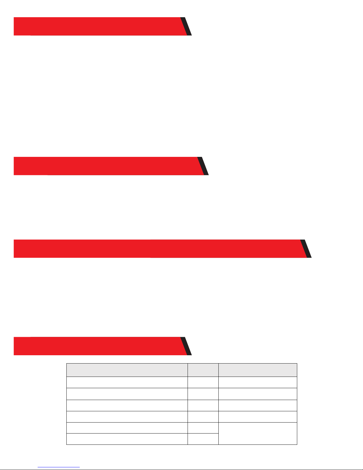
Item
Quantity
Remarks
LCD display unit 1
Data cable (2m)
1 6 cores, RJ12 at both ends
User manual
1
Tapping screws KA3*12mm
4 For installation on a panel
Tapping screws KA4*25mm 4
For installation on a wall
Plastic expansion bolts M6*25mm
4
4. PACKING LIST
Page 3
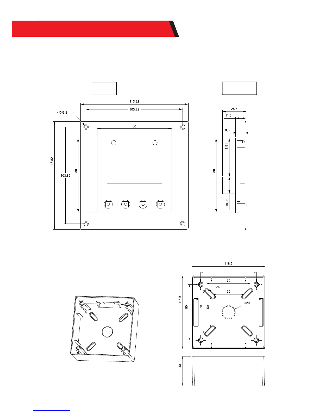
External dimensions: 115.82×115.82mm
Installation dimensions: 96mm or 103.82x103.82mm
Installation hole diameter: ¢3.5 (mm)
Front
Right view
External dimensions: 118.5×118.5×48mm
Installation dimensions: 50×50mm or 70×70mm
Installation hole diameter: ¢5(mm)
5.2、Installation on a wall
5. INSTALLATION INSTRUCTIONS
5.1 Installation on a controller case or panel
Page 4
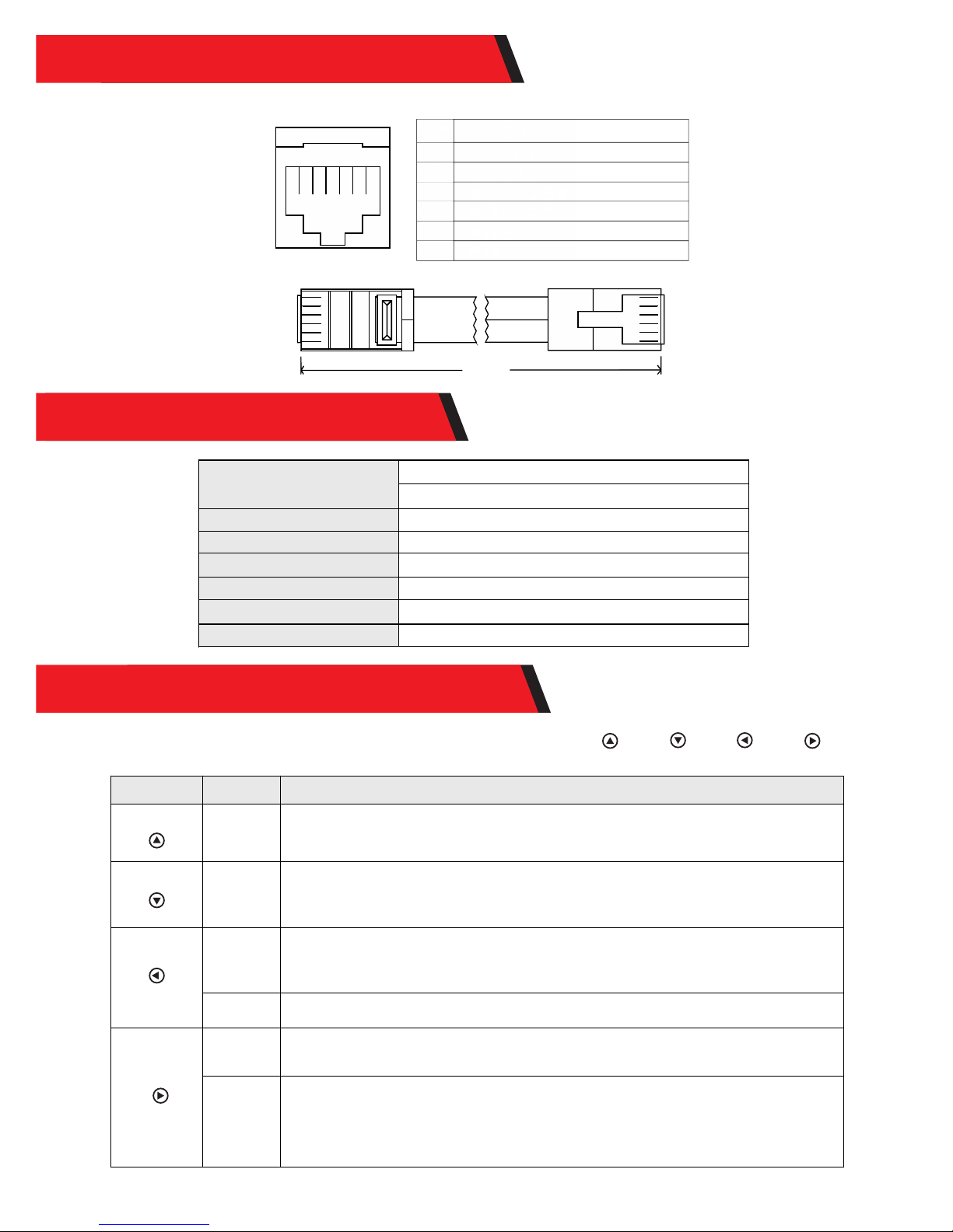
Controller communication port RJ12 and the core series number is as follows:
No
①
②
③
④
⑤
⑥
① ② ③ ④ ⑤ ⑥
Definition
Receiving terminal RX
Transmitting terminal TX
Power supply grounding/ signal grounding
Power supply grounding/ signal grounding
Power supply positive
Power supply positive
Data cable, RJ12 (6-pin) connector
①
②
③ ④ ⑤ ⑥
①
②
③ ④ ⑤ ⑥
2m long
The pr oduct des ign features 4 keys which, from left to right, are:“ ”、“ ”、“ ”、“ ”
They equ al to ("UP" , "DOWN", " ESC", "OK ")
Key Operation
Tap, press
and hold
Tap, press
and hold
Tap
Press and
hold
Tap
Press and
hold
Description
1) When browsing a menu , tap the key for a page up;
2) In parameter setting, tap the key to increase the value by a minimum unit;
3) Press and hold the key for quick page-up movement or value increasing.
1) When browsing a menu , tap the key for a page down;
2) In parameter setting, tap the key to decrease the value by a minimum unit;
3) Press and hold the key for quick page-down movement or value decreasing.
1) When browsing a menu, tap the key to return to the previous level, until the main
menu is reached;
2) In the setting mode, a tap on this key can cancel the data modification in process
and exit the setting mode.
In any menu, press and hold the key to immediately skip to the "error code page for
convenient checkup.
1) In a menu which contains submenus, tap the key to enter into a submenu;
2) In a menu with settable or adjustable parameters, tap the key to enter into or
confirm parameter setting.
If "manual mode" is selected as the load mode, a press-and-hold on the key to
switch on/ off the load.
If it's not in the manual mode, a press-and-hold will cause the display to skip to the
load mode setting interface as a reminder.
(Note: if no load is connected to the controller, this function and related load
parameters will become inoperative.)
6. DATA CABLE DEFINITION
7. PARAMETER DETAILS
8. USAGE OF NAVIGATION KEYS
Static power consumption
LCD backlight on <35mA/12V
Communication port
RS232
Operating temperature
0.5kg
Product weight
LCD backlight off <25mA/12V
-35℃ to+65℃;
115.82×115.82 (mm) (L×W)
Baud rate
9600bps
Communication port
Dimensions
Rj12 (6-pin)
Page 5
K AM P PT RC
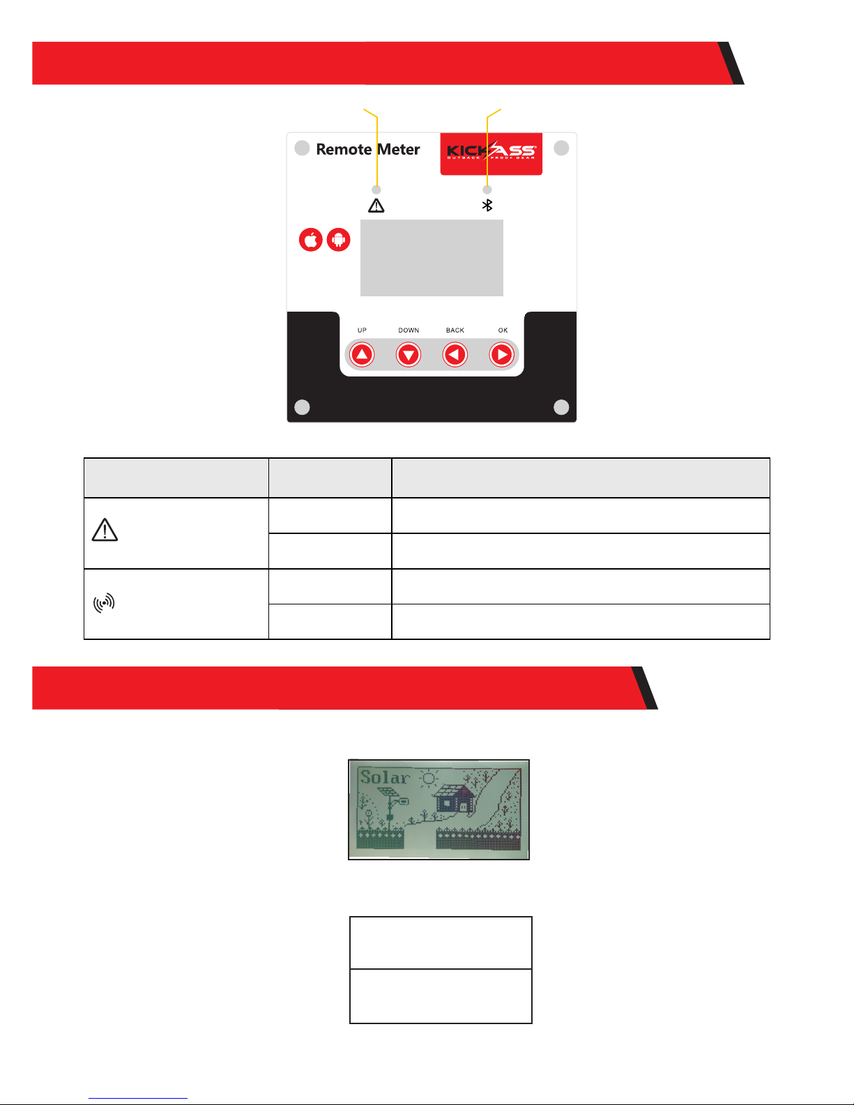
Indicator
State
Description
System fault indicator
Steady off
The controller system is normal
Quick flashing
Abnormality occurs to the controller system(Please check
the error code)
Communication
connection indicator
Steady off
Communication connection between the LCD display unit
and controller is normal
Slow flashing
Communication connection between the LCD display unit
and controller abnormality
When the "startup screen" is displayed, tap any key to skip it. If no operation is detected within 5 seconds,
a "Connecting " interface will ensue:
"Connecting" interface. When connection is successfully done, the "main menu" will appear:
Solar Controller
Connecting...
9. FAULT INDICATION AND COMMUNICATION INDICATION
10. SYSTEM MENU AND PARAMETER SETTINGS
Communication fault indicator
Communication connection indicator
Page 6
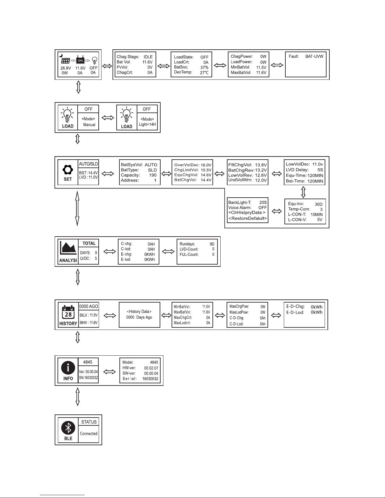
10.1 Menu block diagram
Main menu
Real-time
monitoring
Load mode
Parameters
setting
Statistic data
Historical data of
the current day
Device
information
Bluetooth connection state
(This menu is available only to the display units with the optional bluetooth function)
Refer to "Usage of Navigation Keys" for operations including entering into and
exiting each of the above menus, related parameters setting, etc.
Page 7
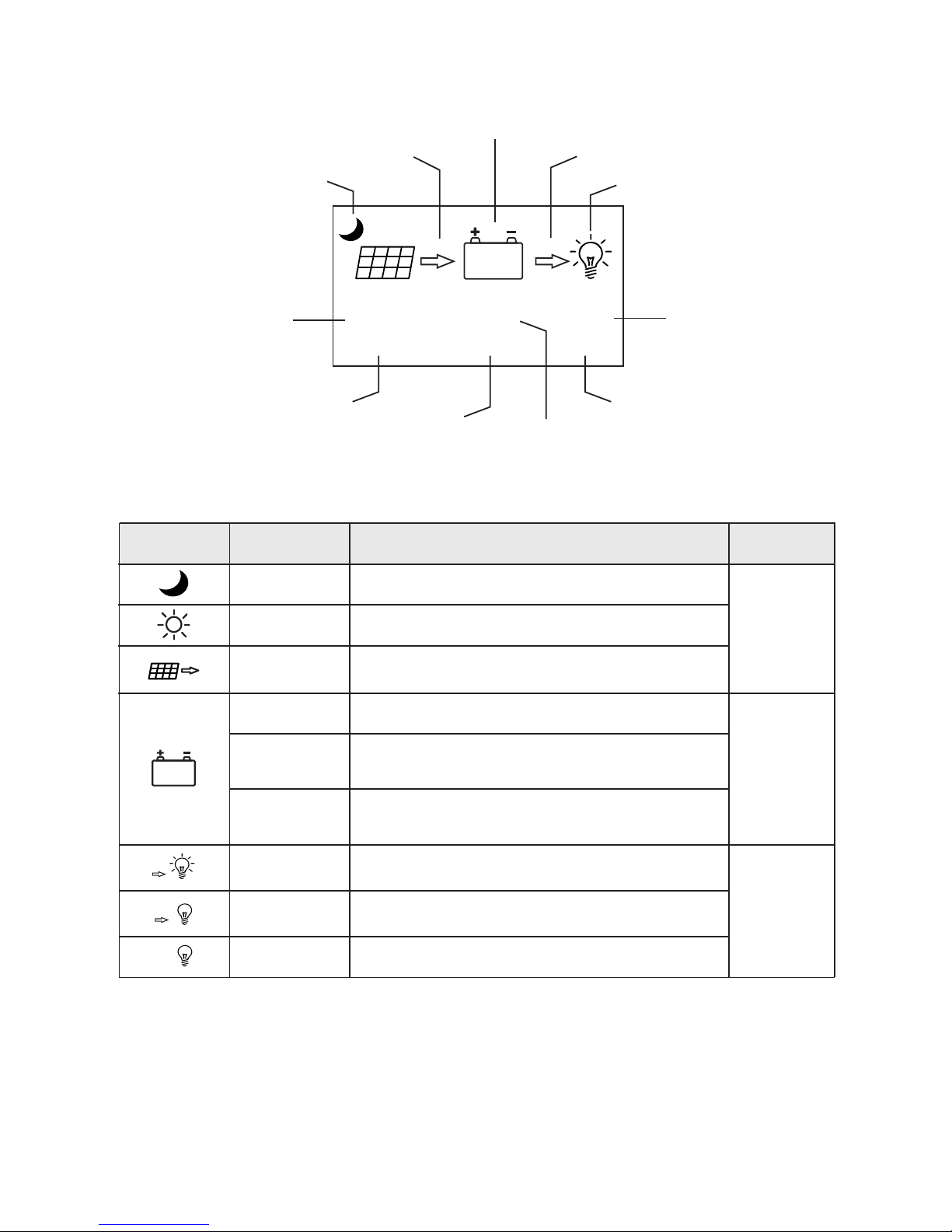
Definitions of "main menu" icons
Icon or value
State
Description
Remarks
Steady on
"0~100%"
"0%"in slow
flashing
"100%"in quick
flashing
Nighttime
Daytime
A dynamic arrow indicates charging is in process,
while a static one indica tes otherwise.
Current battery capacity
Battery over-discharged
Battery over-voltage
A bulb shown as left and a dynamic arrow indicate the
load is switched on.
A bulb shown as left and a static arrow indicate
the load is switched off.
Overloa d or short-circuit protection
Day or night indicating icon
Charging current icon
Battery icon and SOC
Load current icon
Load icon and state indication
charging power
load current
Battery voltage
37%
26.8V 11.6V
0W 0A
OFF
0A
37%
Related to
charging
Related to
battery
Related to
load
10.2 Main menu
Solar panel voltage
charging current
Load state
Steady on
Steady on
Steady on
Steady on
Quick flashing
Page 8
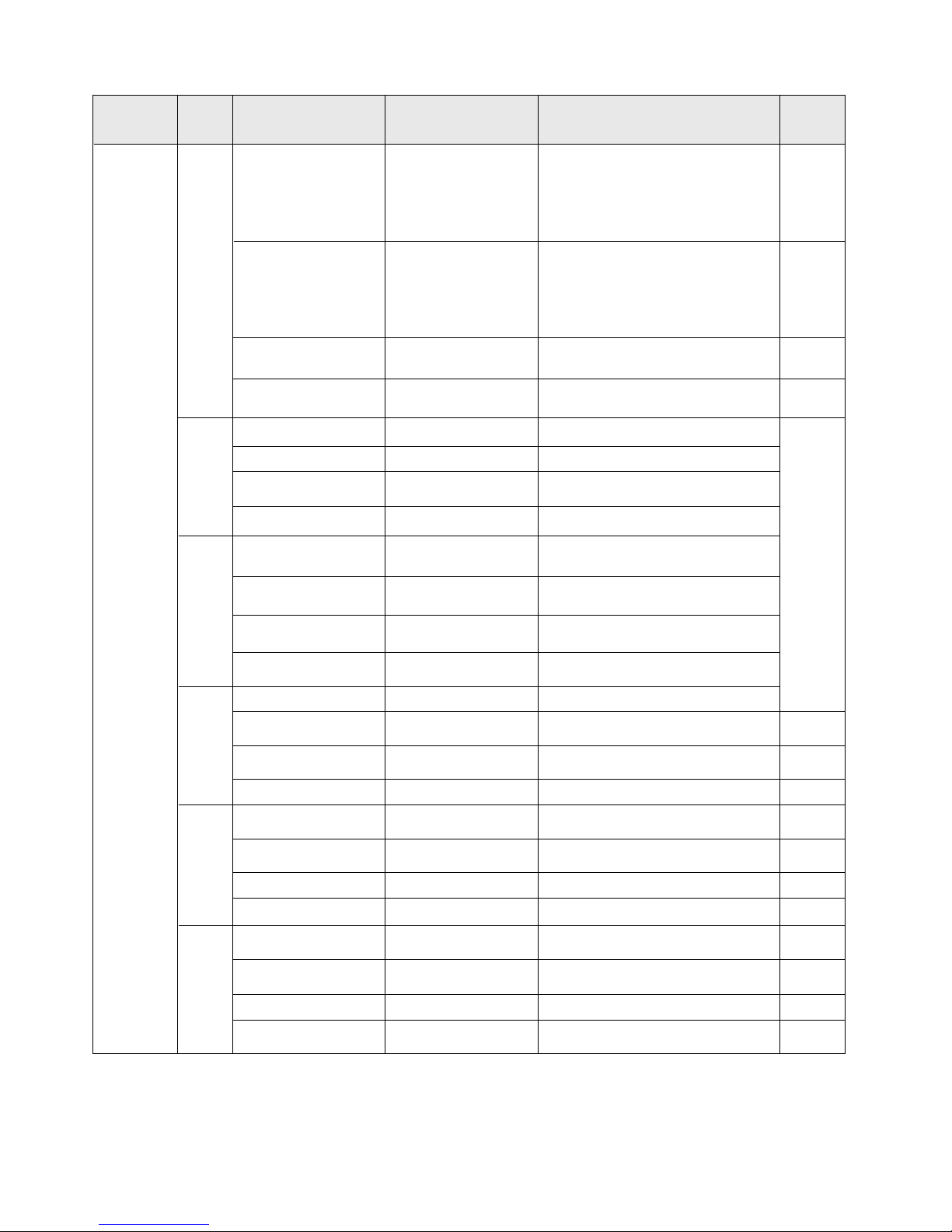
Parameter settings list
Menu level
Page Item to set
1
Battery system
voltage
BatSysVol :
Battery type
BatType:
Nominal battery
capacity
Capacity :
Device address
Parameter and setting range Remarks
“
12V ”12Vsystem
“24V”24Vsystem
“36V”36Vsystem
“
48V ”48Vsystem
“
AUTO” auto recognition
“SLD”sealed lead-acid battery
“FLD” open lead-acid battery
“GEL” gel battery
“LI ” lithium battery
“USE”user defined
0~9999
± 5
Address : 1~60 ± 1
2
Over-voltage threshold OverVolDsc: 9.0~17.0V
Charging limit voltage ChgLimtVol : 9.0~17.0V
*n,±1
Equalizing charging
voltage
EquChgVol:
9.0~17.0V
Boost charging voltage
BstChgVol :
9.0~17.0V
3
Floating charging
voltage
FltChgVol
:
9.0~17.0V
Boost charging
recovery voltage
BstChgRev
:
Over-discharge
recovery voltage
LowVolRev
:
Under-voltage
warning level
UndVolWrn
:
4
Over-discharge voltage LowVolDsc :
Over-discharge time
delay
LVD Delay:
0~60s
± 1
Equalizing charging
time
Equ-Time:
0~300 MIN
± 1
Boost charging time
Bst-Time: 0~300 MIN ± 1
5
Equalizing charging
interval
Equ-Inv : 0~30 D(days )
± 1
Temperature
compensation
Temp-Com:
-(3~5)mV/℃/2V
± 1
Light control time
L-CON-T: 0~60 MIN ± 1
Light control voltage
L-CON-V: 5~11V
*n,± 1
6
LCD screen backlight
time
BackLight-T :
± 1
Fault voice alarm;
Voice Alarm :
Clear historical data <ClrHistoryData>
Reset to factory
settings
<Restore Default>
Note:
1) In this manual, "n" assigned with a value of 1, 2, 3 or 4 denotes a battery system o f 12V, 24 V, 36V
or 48V accordingly.System voltage indication
2) Before setting parameters, first refer to the U ser Man ual of th e corre spond ing con troll er. As some
parameters are not settable, operation of setting these parameters on the di splay u nit wil l be deem ed as
invalid or impossible by the controller.
9.0~17.0V
9.0~17.0V
9.0~17.0V
9.0~17.0V
2 st-level
menu
1 to 600s (ON indicates the
screen is lit constantly)
"ON", voice alarm enabled
"OFF", voice alarm disabled
Select "YES" for execution
Select "YES" for execution
Displayed item/
parameter
10.3 Parameter Settings
Page 9
1) All voltage values are based on 12 volt system settings. For example for a 24 volt system
most parameter setting will need to be doubled.
2) Tap the up or down key to select parameter to be set then tap the right arrow button
and the parameter or sign will flash continue to tap the up or down button then tap the
ok button again to confirm setting.
3) For parameters on the current menu, the ones highlighted are setable, while the ones
underlined are not.
10.4.1 Controller Charging And Discharging Related Parameters
10.4.2 Lcd Screen Backlight Setting
Displayed item/ parameter
Description
BackLight-T: ON The LCD screen is lit constantly
BackLight-T:
20S
The setting range of LCD screen backlight time is 1 to 600s
Enter into setting menu and tap up or down to move to “backlight-t”: 20s
Tap ok to enter into the setting mode and tap up or down to modify the value within the setting range “on”
indicates the screen will be constantly lit and the range for backlight time will be 1 to 600 seconds. Tap ok
to confirm settings.
10.4.3.controller Abnormality Voice Alarm On/off Setting
Displayed item/ parameter Description
Voice Alarm: ON Voice alarm enabled
Voice Alarm: OFF Voice alarm disabled
Alarm type
No Alarm System running well or wa
Alarming 1min
Battery over-discharge, Load short circuit/overload, controller
or battery over-temperature
Alarming 15s
Alarming persistent
Battery under-voltage
Battery over-voltage,solar panel reverse connection,solar
panel over voltage
Buzzer state
Enter into the setting manual, tap up or down to select voice alarm: xxx, tap ok to enter into the parameter
mode and then tap up or down to switch between on and off tap ok to confirm the modification or tap the
back button to cancel.(the voice alarm is disabled from factory setting.
10.4.4 Clear Data And Reset To Factory Settings
Tap the ok key to enter into the submenu and a no and yes menu will pop up use up or
down keys to select yes and tap ok again and yes will flash a few times if no is selected tap
ok to return to previous display.
Page 10
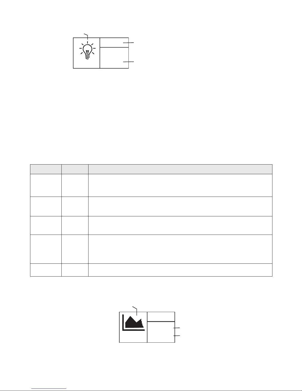
10.5 Load Modes
LOAD
OFF
<Mode>
Manual
Load mode setting icon
Load state
Load mode
1) If the characters above the “<mode>” are on, it indicates that the load is switched on and
off indicates it is switched off
2) Tap the ok key to enter into load setting parameter and below the “<mode>” the display
will flash use the up down keys to select any of the load modes then tap ok to confirm
setting.
3) Press and hold ok in any menu but not in setting mode: if the current mode is “manual’
mode pressing and holding the key will switch the load on and off. If the current load
mode is not manual mode pressing and holding the ok key will cause the display to skip
to the load mode setting interface and a reminder will pop up telling the user in this
mode, pressing and holding the key will not switch on/off the load.
4) Note: this parameter is ineffective for controllers without loads.
Load mode
Mode
characters
Description
Sole light
control mode
Light+On
Light control
+ time
control mode
1 to 14H
Light+ 01H
...
Light+
14
H
Manual
mode
Manual
Debugging
mode
Debug
Normal on
mode
Normal On
The solar panel voltage is lower than the light control on voltage, and after a
preset time delay , the controller will switch on the load;
The solar panel voltage is higher than the light control off voltage, and after
a preset time delay , the controller will switch off the load.
The solar panel voltage is lower than the light control on voltage, and after a
time delay, the controller will switch on the load. From this point on, the load
will work for a preset period of time (1 to 14 hours) before being switched off.
In this mode, whether it's day or night, users can press and hold the "OK"
key to switch on or off the load; this mode is often used in some special
occasions or during commissioning.
As long as the solar panel voltage is lower than the light control on voltage,
the controller will immediately switch on the load;
As soon as the solar panel voltage gets higher than the light control off
voltage, the controller will immediately switch off the load.
This mode is usually used during system installation and commissioning.
This mode is suitable for applications requiring 24-hour operation, and after
being switched on, the load keeps outputting in this mode.
Includ ing total charging amp-h rs, to tal discharging amp-hr s, tot al power consum ptio n, numbers of
operat ing da ys, over-disch arges and f ull- charges
ANALYSI
TOTAL
DAYS: 9
LVDC: 5
Number of operating days: 9
Number of over-discharges:5
Statistics icon
10.6 Static Data
Page 11
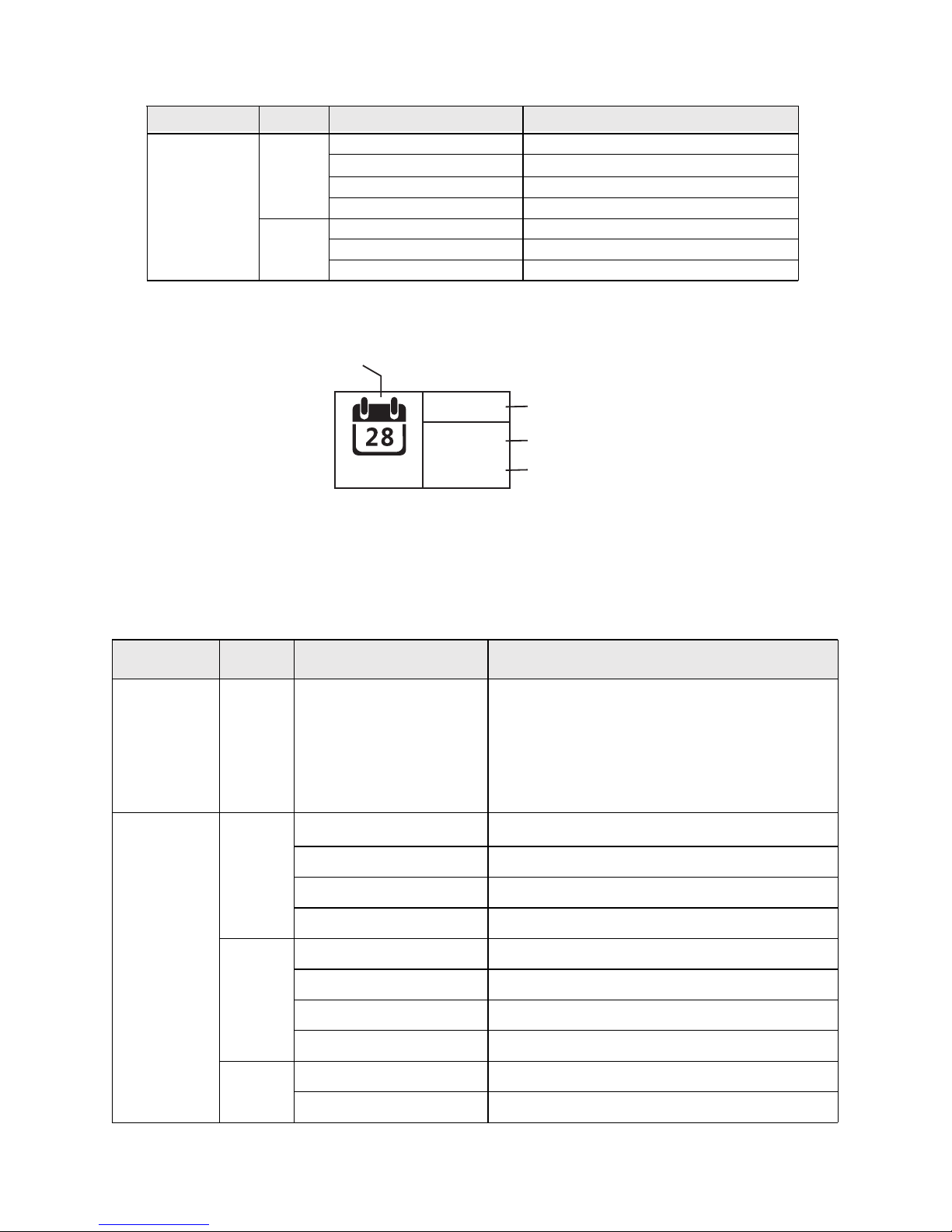
10.7、Historical data of the current day
(Historical data including: the current day's min. battery v oltag e, the cu rrent d ay's ma x. batt ery
voltage, the current day's max. charging current, the current day's m ax. dis charg ing cur rent, t he curr ent
day's max. charging power, the current day's max. discharging power, the current day's charg ing amp hrs, the current day's discharging amp-hrs, the current day's total p ower ge nerat ion and t he curr ent
day's total power consumption)
HISTORY
0000 AGO
BtLV :
BtHV:11.6V
11.5V
Historical data icon
Historical data of day xxxx (counting backwards)
The current day's min. battery voltage is 11.5V
The current day's max. battery voltage is 11.6V
Menu level
Page
Displayed item/
parameter
Description
<History
Data>
xxxx
Days
Ago
1
MinBatVol: 11.5V
MaxBatVol: 11.6V
MaxChgVol : 0A
MaxLodVol: 0A
2
MaxChgPow: 0W
MaxLodPow: 0W
C-D-Chg
:
0AH
C-D-Lod:
0AH
3
E-D-Chg: 0kWh
E-D-Lod
0kWh
:
1
Xxxx:select the historical data of day xxxx
(counting backwards)
0000: the current day
0001: yesterday
0002: the day before yesterday
The selected day's min. battery voltage
The selected day's max. battery voltage
The selected day's max. charging current
The selected day's max. discharging current
The selected day's max. charging power
The selected day's max. discharging power
The selected day's total charging amp-hrs
The selected day's total discharging amp-hrs
The selected day's total power generation
The selected day's total power consumption
2st-level
menu
3st-level
menu
DescriptionMenu level Page Displayed item/ parameter
2
LVD-Count: 0
FUL-Count: 0
2nd-level
menus
1
C-chg: 0AH
C-lod: 0AH
E-chg: 0KWH
E-lod: 0KWH
Rundays: 10D
Total charging amp-hrs
Total discharging amp-hrs
Total power generation
Total power consumption
Total number of operating days
Total number of over-discharges
Total number of full-charges
Page 12
The contents of this manual are subject to change without prior notice.
The screen won't light up after being
turned on
The screen is stuck at "Connecting..."
The fault indicator flashes quickly
The communication indicator flashes slowly
The bluetooth interface displays:
"Disconnect"
Check whether the communication cable has the right core order, the connection
is properly done and the controller functions normally, etc.
Some abnormality occurs to the controller. Check the error code, pinpoint the
cause, analyze and solve it.
Communication between the display unit and controller is abnormal. Check the
connection cable and controller.
The Bluetooth communication status is shown as:
1) The mobile App is not connected to the controller;
2) The device is visible to the mobile App's search, but the problem still lingers
on. Check the cable connecting the display unit and the controller;
3) The device is invisible to the mobile App's search. Check whether it has been
paired with some other mobile phone;
(Note: this menu is only available to the display units with the optional bluetooth
function)
Code:1.1.24.01469
Symptoms Causes and solutions
Model :
4845
HW-ver:
00.02.07
SW-ver: 00.00.04
Serial: 160300032
10.9 Bluetooth connection status
BLE
STATUS
Connected
Bluetooth icon
Indicating a bluetooth connection status
1
2st-level
menu
Controller model
Hardware version
Software version
Controller serial number
① When "Disconnect" is displayed on the screen, it indicates no Bluetooth device is cur rentl y
connected.
②When "Connected", it indicates some Bluetooth device has been connected.
③ Bluetooth functions and this menu are only available to the "RM-5B" display unit, and not the "R M-5"
unit.
④ The App is only compatible with Android phones with an OS version of 4.3 or above and iphones.
Menu level
Page
Item
Description
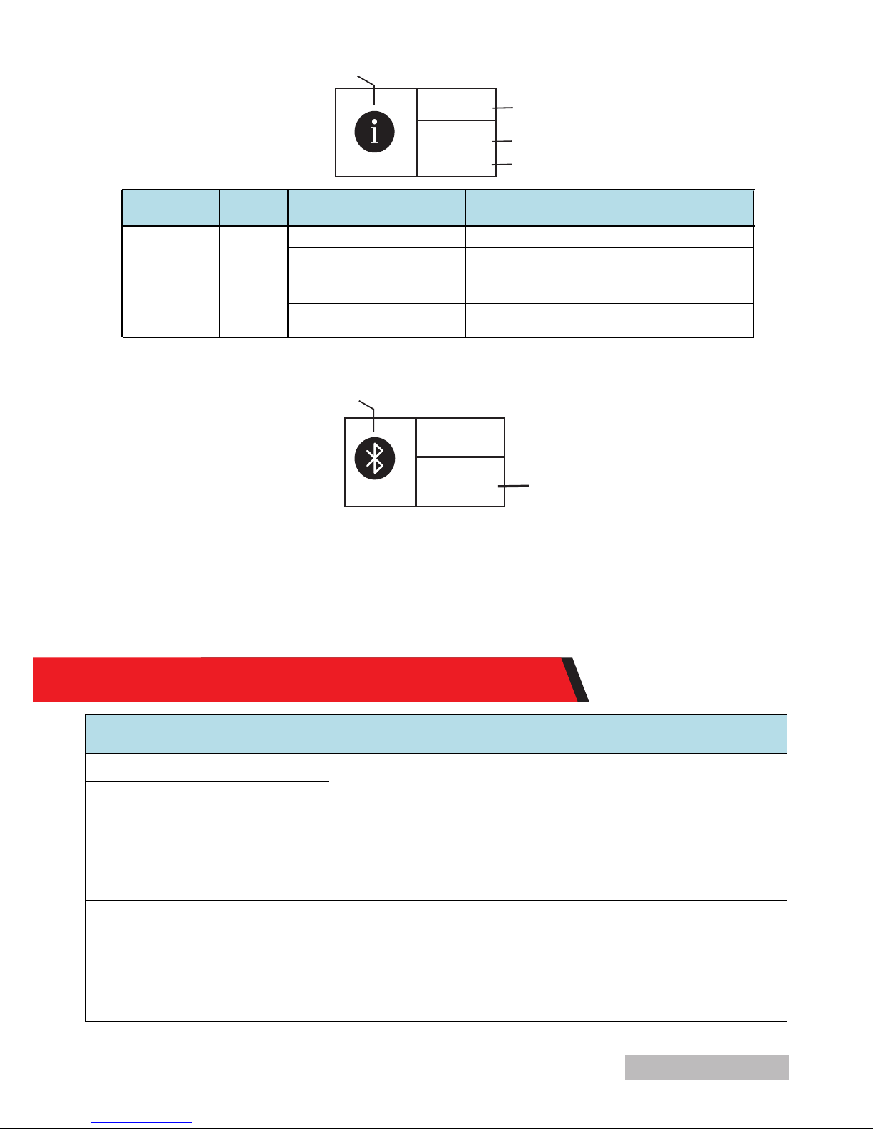
10.8 Device information
INFO
4845
Ver:
00.00.04
SN:
16030032
Device information icon
Product model
Software version
Product serial number
11. COMMON PROBLEMS AND SOLUTIONS
 Loading...