

Page 1
1) Place socket assembly inside shade. Pass threaded pipe on top of socket assembly
GREEN GROUND
SCREW
CUPPED
WASHER
A
B
OUTLET BOX
GROUND
FIXTURE
GROUND
DIMPLES
WIRE CONNECTOR
(NOT PROVIDED)
OUTLET BOX
GROUND
GREEN GROUND
SCREW
FIXTURE
GROUND
Connect Black or
Red Supply Wire to:
Connect
White Supply Wire to:
Black White
*Parallel cord (round & smooth) *Parallel cord (square & ridged)
Clear, Brown, Gold or Black
without tracer
Clear, Brown, Gold or Black
with tracer
Insulated wire (other than green)
with copper conductor
Insulated wire (other than green)
with silver conductor
*Note: When parallel wires (SPT I & SPT II)
are used. The neutral wire is square shaped
or ridged and the other wire will be round in
shape or smooth (see illus.)
Neutral Wire
ARANDELA
CONCAVA
A
B
TIERRA DE LA
CAJA DE SALIDA
TORNILLO DE TIERRA,
VERDE
DEPRESIONES
TIERRA
ARTEFACTO
CONECTOR DE ALAMBRE
(NO SE PROVEE)
TIERRA DE LA
CAJA DE SALIDA
TORNILLO DE TIERRA,
VERDE
TIERRA
ARTEFACTO
Conectar el alambre de
suministro negro o rojo al
Conectar el alambre de
suministro blanco al
Negro Blanco
*Cordon paralelo (redondo y liso)
*Cordon paralelo (cuadrado y estriado)
Claro, marrón, amarillio o negro
sin hebra identificadora
Claro, marrón, amarillio o negro
con hebra identificadora
Alambre aislado (diferente del verde)
con conductor de cobre
Alambre aislado (diferente del
verde) con conductor de plata
*Nota: Cuando se utiliza alambre paralelo
(SPT I y SPT II). El alambre neutro es de forma
cuadrada o estriada y el otro alambre será de
forma redonda o lisa. (Vea la ilustracíón).
Hilo Neutral
up through hole in top of shade.
2) Screw bottom of center column on to threaded pipe protruding from top of shade.
3) Pass threaded pipe up through hole in shade. Screw end of threaded pipe into
coupling on bottom of socket assembly.
4) Thread finial onto end of threaded pipe protruding from bottom of shade.
5) Insert recommended bulbs.
6) Screw center stem to top of center column.
7) Pass wire through stem and screw stem to top of center stem.
NOTE: Thread locking compound must be applied to all stem threads as noted
with symbol (3) to prevent accidental rotation of fixture during cleaning,
relamping, etc.
8) Attach small loop to stem.
9) TURN OFF POWER.
IMPORTANT: Before you start, NEVER attempt any work without shutting off the
electricity until the work is done.
a) Go to the main fuse, or circuit breaker, box in your home. Place the main
power switch in the “OFF” position.
b) Unscrew the fuse(s), or switch “OFF” the circuit breaker switch(s), that
control the power to the fixture or room that you are working on.
c) Place the wall switch in the “OFF” position. If the fixture to be replaced has
a switch or pull chain, place those in the “OFF” position.
10) Take threaded pipe from parts bag and screw in screw collar loop a minimum of 6 mm
(1/4”). Lock into place with hexnut.
11) Run another hexnut down threaded pipe almost touching first hexnut. Now screw
threaded pipe into mounting strap. Mounting strap must be positioned with extruded
thread faced into outlet box. Threaded pipe must protrude out the back of mounting
strap. Connect mounting strap to outlet box.
12) Unscrew the threaded ring from screw collar loop. Take canopy and pass over
screw collar loop. Approximately one half of the screw collar loop exterior threads
should be exposed. Adjust screw collar loop by turning assembly up or down in
mounting strap. Remove canopy.
13) After desired position is found, tighten top hexnut up against the bottom of the
mounting strap.
14) Slip canopy over screw collar loop and thread on threaded ring. Attach chain (with
fixture connected) to bottom of screw collar loop. Unscrew threaded ring, let
canopy and threaded ring slip down.
15) Weave electrical wire and ground wire through chain links no more than 3 inches
apart. Pass wire through threaded ring, canopy, screw collar loop, threaded pipe
and into outlet box.
16) Grounding instructions: (See Illus. A or B).
A) On fixtures where mounting strap is provided with a hole and two raised
dimples. Wrap ground wire from outlet box around green ground screw, and
thread into hole.
B) On fixtures where a cupped washer is provided. Attach ground wire from
outlet box under cupped washer and green ground screw, and thread into
mounting strap.
If fixture is provided with ground wire. Connect fixture ground wire to outlet box
ground wire with wire connector (not provided.) after following the above steps.
Never connect ground wire to black or white power supply wires.
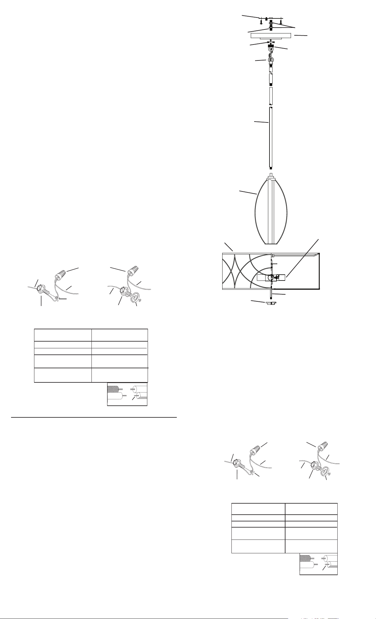
MOUNTING STRAP
ABRAZADERA DE
MONTAJE
THREADED PIPE
TUBO ROSCADO
THREADED RING
ANILLO ROSCADO
STEM
VARILLA
CENTER COLUMN
COLUMNA CENTRAL
SHADE
PANTALLA
LOOP
LAZO
HEXNUT
TUERCA
HEXAGONAL
CANOPY
ESCUDETE
SCREW COLLAR LOOP
OJAL DE COLLAR
ROSCADO
3
3
3
SOCKET ASSEMBLY
CONJUNTO DEL
CASQUILLO
17) Make wire connections (connectors not provided). Reference chart below for correct
connections and wire accordingly.
18) Raise canopy to ceiling
19) Secure canopy in place by tightening threaded ring onto screw collar loop.
1) Ponga el conjunto del casquillo adentro de la pantalla. Pase el tubo roscado
encima del conjunto del casquillo arriba a través del agujero en la parte superior
de la pantalla.
2) Atornille la parte inferior de la columna central en el tubo roscado que sobresale
de arriba de la pantalla.
3) Pase el tubo roscado arriba a través del agujero en la pantalla. Atornille el
extremo del tubo roscado en el acoplamiento en la parte inferior del conjunto del
casquillo.
4) Rosque el capuchón en el extremo del tubo roscado que sobresale de la parte
inferior de la pantalla.
5) Inserte las bombillas recomendadas.
6) Atornille el vástago central al arriba del cuerpo del artefacto.
7) Pase el alambre del artefacto a través de la varilla y atornille la varilla el parte
superior del artefacto. Nota: Debe aplicarse un compuesto para el sellado de
roscas en todas las roscas de las varillas indicadas con el símbolo (4) para evitar
la rotación accidental del artefacto durante su limpieza, cambio de bombillas, etc...
8) Una la argolla pequeña a la última varilla.
9) APAGUE LA ALIMENTACIÓN ELÉCTRICA.
IMPORTANTE: Antes de comenzar, NUNCA trate de trabajar sin antes
desconectar la corriente hasta que el trabajo se termine.
a) Vaya a la caja principal de fusibles, o interruptor o caja de circuitos de su
casa. Coloque el interruptor de la corriente principal en posición de
apagado “OFF”.
b) Desatornille el (los) fusible (s), o coloque el interruptor o interruptores del
breaker en posición de apagado “OFF”, que controla (n) la corriente hacia
el artefacto o habitación donde está trabajando.
c) Coloque el interruptor de pared en posición de apagado “OFF”. Si el
artefacto que se va a reemplazar tiene un interruptor o cadena que se jala,
colóquelos en la posición de apagado “OFF”.
10) Seque el tubo roscado de la bolsa de piezas y atornille en el ojal de collar roscado
un minimo de 6 mm (1/4”). Inmovilice en el lugar con la tuerca hexagonal.
11) Instale otra tuerca hexagonal en el tubo roscado casi tocando la primera tuerca
hexagonal. Ahora, atornille el tubo roscado en la abrazadera de montaje. La
abrazadera de montaje se debe colocar con la rosca extruida mirando hacia la
caja de salida. El tubo roscado debe sobresalir atrás de la abrazadera de montaje.
Conecte la abrazadera de montaje a la caja de salida.
Date Issued: 10/9/09
FINIAL
CAPUCHON
THREADED PIPE
TUBO ROSCADO
12) Destornille el anillo roscado del ojal de collar roscado deben sobresalir aproxima
damente la mitad. Ajuste el ojal del collar roscado girando el conjunto hacia arriba
a abajo, en la abrazadera de montaje. Retire el escudete.
13) Después que encuentre la posición deseada, apriete la tuerca hexagonal superior
contra el fondo de la abrazadera de montaje.
14) Resbale el escudete sobre el ojal de collar roscado y enrosque en el anillo
roscado. Conecte la cadena (con el portalámparas conectado) al fondo del ojal
de collar roscado. Destornille el anillo roscado, deje que el escudete y el anillo
roscado resbalen hacia abajo.
15) Pase el alambre eléctrico y el alambre de tierra a través de los estabones de la
cadena, a espacios maximos de 3 pulgadas. Pase el alambre a través del anillo
roscado, el escudete, el ojal de collar roscado, el tubo roscado y dentro de la caja
de salida.
16) Instrucciones de conexión a tierra solamente para los Estados Unidos. (Vea la
ilustracion A o B).
A) En las lámparas que tienen el fleje, de montaje con un agujero y dos
hoyuelos realzados. Enrollar el alambre a tierra de la caja tomacorriente
alrededor del tornillo verde y pasarlo por el aquiero.
B) En las lámparas con una arandela acopada. Fijar el alambre a tierra de la
caja tomacorriente del ajo de la arandela acoada y tornillo verde, y paser
por el fleje de montaje.
Si la lámpara viene con alambre a tierra. Conecter el alambre a tierra de la lám
para al alambre a tierra de la caja tomacorriente con un conector de alambres
(no incluido) espués de seguir los pasos anteriores. Nunca conectar el alambra a
tierra a los alambres eléctros negro o blanco.
17) Haga les conexiones de los alambres (no se proveen los connectores.) La tabla
de referencia de abajo indica las conexiones correctas y los alambres correspondientes.
18) Levante el escudete hasta el cielorraso.
19) Asegure en el escudete en el lugar apretando el anillo roscado en el ojal de collar
roscado.
IS-65325-US
 Loading...