

Page 1
1) TURN OFF POWER.
SCREW
IMPORTANT: Before you start, NEVER attempt any work
without shutting off the electricity until the work is done.
a) Go to the main fuse, or circuit breaker, box in your
home. Place the main power switch in the “OFF”
position.
b) Unscrew the fuse(s), or switch “OFF” the circuit breaker
switch(s), that control the power to the fixture or room
that you are working on.
c) Place the wall switch in the “OFF” position. If the fixture
to be replaced has a switch or pull chain, place those in
the “OFF” position.
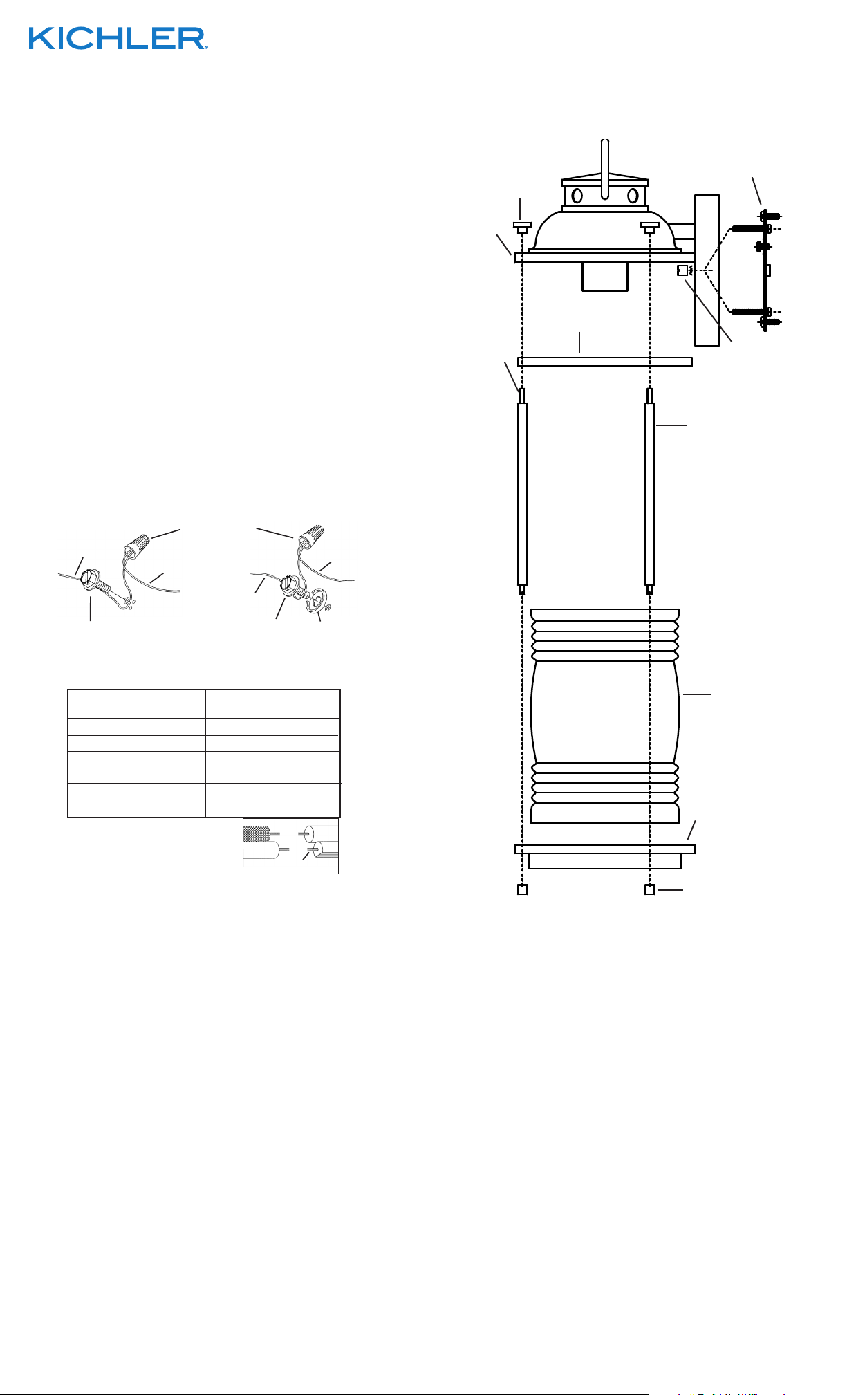
2) Find the appropriate threaded holes on mounting strap.
Assemble mounting screws into threaded holes.
3) Attach mounting strap to outlet box. (Screws not provided).
Mounting strap can be adjusted to suit position of fixture.
4) Grounding instructions: (See Illus. A or B).
A) On fixtures where mounting strap is provided with a hole
and two raise dimples. Wrap ground wire from outlet
box around green ground screw, and thread into hole.
B) On fixtures where a cupped washer is provided. Attach
ground wire from outlet box under cupped washer and
green ground screw, and thread into mounting strap.
If fixture is provided with ground wire. Connect fixture
ground wire to outlet box ground wire with wire connector.
(Not provided.) After following the above steps. Never connect
ground wire to black or white power supply wires.
A
OUTLET BOX
GROUND
GREEN GROUND
WIRE CONNECTOR
(NOT PROVIDED)
FIXTURE
GROUND
DIMPLES
OUTLET BOX
GROUND
GREEN GROUND
SCREW
B
CUPPED
WASHER
FIXTURE
GROUND
FINIAL
CAPUCHÓN
ROOF
TECHO
LONG THREADED
STUD
ESPÁRRAGO
ROSCADO LARGO
We’re here to help 866-558-5706
Hrs: M-F 9am to 5pm EST
MOUNTING STRAP
PLANCHA PARA
MONTAR
RING
ANILLO
THREADED BALL
BOLA ROSCADO
ROD
VARILLA
5) Make wire connections (connectors not provided.) Reference
chart below for correct connections and wire accordingly.
Connect Black or
Red Supply Wire to:
Black White
*Parallel cord (round & smooth) *Parallel cord (square & ridged)
Clear, Brown, Gold or Black
without tracer
Insulated wire (other than green)
with copper conductor
*Note: When parallel wires (SPT I & SPT II)
are used. The neutral wire is square shaped
or ridged and the other wire will be round in
shape or smooth (see illus.)
Insulated wire (other than green)
Connect
White Supply Wire to:
Clear, Brown, Gold or Black
with tracer
with silver conductor
Neutral Wire
6) Push fixture to wall, carefully passing mounting screws
through holes in fixture.
7) Thread threaded balls onto mounting screws. Tighten
threaded balls to secure fixture to wall.
8) Insert recommended bulb.
9) Raise ring up to fixture. Fit ring inside edge of roof.
10) With rod positioned so the longer threaded stud on the rod
is on top of the rod, raise one rod up to fixture. Pass long
threaded stud on end of rod up through hole in ring and hole
in roof. Thread finial on to end of rod protruding from top of
roof.
11) Repeat step 9 for remaining rods.
12) Raise glass up to fixture. Fit glass in between rods. Pass
hole in top of glass over bulb and socket. Fit top edge of
glass inside roof.
13) Raise bottom cap up to fixture. Pass small holes along edge
of bottom cap over short threaded studs on ends of each
rod. Screw threaded caps onto threaded studs protruding
from bottom of bottom cap. Tighten threaded caps to
secure glass in place. (DO NOT over tighten.)
GLASS
VIDRIO
BOTTOM CAP
TAPA INFERIOR
THREADED CAP
TAPA ROSCADA
INSTRUCTIONS FOR MOUNTING FIXTURE OUTDOORS AND/
OR IN WET LOCATIONS.
14) Mounting surface should be clean, dry, flat and 1/4” larger
that the canopy on all sides. Any gaps between the mounting
surface and canopy exceeding 3/16” should be corrected
as required.
15) With silicone caulking compound, caulk completely around
where back of canopy meets the wall surface to prevent
water from seeping into outlet box.
SEE OTHER SIDE FOR SPANISH TRANSLATIONS.
VEA EL OTRO LADO DE TRADUCCIONES AL ESPAÑOL.
Date Issued: 11/28/14 IS-49569-US
Page 2
1) APAGUE LA ALIMENTACIÓN ELÉCTRICA.
IMPORTANTE: Antes de comenzar, NUNCA trate de trabajar
sin antes desconectar la corriente hasta que el trabajo se
termine.
a) Vaya a la caja principal de fusibles, o interruptor o caja
de circuitos de su casa. Coloque el interruptor de la
corriente principal en posición de apagado “OFF”.
b) Desatornille el (los) fusible (s), o coloque el interruptor o
interruptores del breaker en posición de apagado
“OFF”, que controla (n) la corriente hacia el artefacto o
habitación donde está trabajando.
c) Coloque el interruptor de pared en posición de apagado
“OFF”. Si el artefacto que se va a reemplazar tiene un
interruptor o cadena que se jala, colóquelos en la
posición de apagado “OFF”.
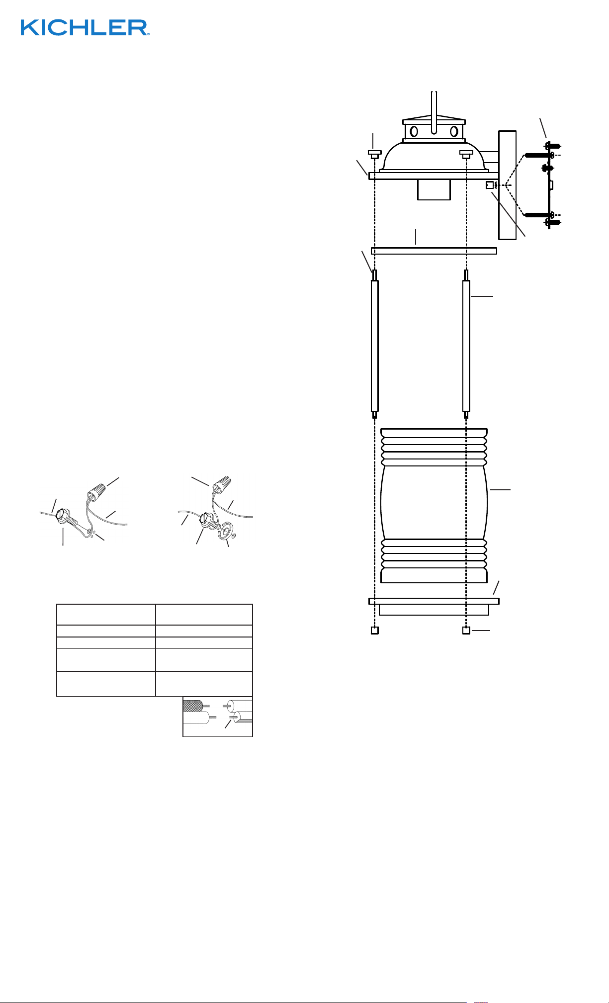
2) Encontrar los agujeros roscados correctos en la abrazadera
de montaje. Instalar los tornillos de montaje en los agujeros
roscados.
3) Unir la abrazadera de montaje a la caja de conexiones. (No se
proveen tornillos). La abrazadera de montaje puede ajustarse
para acomodar la posición del artefacto.
4) Instrucciones de conexión a tierra solamente para los
Estados Unidos. (Vea la ilustracion A o B).
A) En las lámparas que tienen el fleje, de montaje con un
agujero y dos hoyuelos realzados. Enrollar el alambre a
tierra de la caja tomacorriente alrededor del tornillo
verde y pasarlo por el aquiero.
B) En las lámparas con una arandela acopada. Fijar el
alambre a tierra de la caja tomacorriente del ajo de la
arandela acoada y tornillo verde, y paser por el fleje de
montaje.
Si la lámpara viene con alambre a tierra. Conecter el
alambre a tierra de la lámpara al alambre a tierra de la caja
tomacorriente con un conector de alambres. (No incluido)
Espués de seguir los pasos anteriores. Nunca conectar el
alambra a tierra a los alambres eléctros negro o blanco.
A
TIERRA DE LA
CAJA DE SALIDA
CONECTOR DE ALAMBRE
(NO SE PROVEE)
TIERRA
ARTEFACTO
B
TIERRA
ARTEFACTO
FINIAL
CAPUCHÓN
ROOF
TECHO
LONG THREADED
STUD
ESPÁRRAGO
ROSCADO LARGO
We’re here to help 866-558-5706
Hrs: M-F 9am to 5pm EST
MOUNTING STRAP
PLANCHA PARA
MONTAR
RING
ANILLO
THREADED BALL
BOLA ROSCADO
ROD
VARILLA
GLASS
VIDRIO
TIERRA DE LA
CAJA DE SALIDA
TORNILLO DE TIERRA,
VERDE
ARANDELA
CONCAVA
TORNILLO DE TIERRA,
VERDE
DEPRESIONES
5) Haga les conexiones de los alambres (no se proveen los
connectores.) La tabla de referencia de abajo indica las
conexiones correctas y los alambres correspondientes.
Conectar el alambre de
suministro negro o rojo al
Negro Blanco
*Cordon paralelo (redondo y liso)
Claro, marrón, amarillio o negro
sin hebra identificadora
Alambre aislado (diferente del verde)
con conductor de cobre
*Nota: Cuando se utiliza alambre paralelo
(SPT I y SPT II). El alambre neutro es de forma
cuadrada o estriada y el otro alambre será de
forma redonda o lisa. (Vea la ilustracíón).
Conectar el alambre de
suministro blanco al
*Cordon paralelo (cuadrado y estriado)
Claro, marrón, amarillio o negro
con hebra identificadora
Alambre aislado (diferente del
verde) con conductor de plata
Hilo Neutral
6) Empuje la unidad contra la pared, pasando con cuidado al
tubo roscado a travès del agujero.
7) Sujete la unidad contra la pared apretándola con la bola
roscada.
8) Inserte la bombilla recomendada.
9) Levante el anillo hasta el artefacto. Coloque el anillo en el
borde del techo.
10) Con la varilla posicionada de tal manera que el espárrago
roscado más largo en la varilla está en la parte superior
de la varilla, eleve una varilla hacia el artefacto. Pase el
espárrago roscado largo en el extremo de la varilla hacia
arriba a través del agujero en el anillo y agujero en el techo.
Enrosque el capuchón en el extremo de la varilla que
sobresale desde la parte superior del techo.
11) Repita el paso 10 para las varillas restantes.
12) Eleve el vidrio hacia el artefacto. Ajuste el vidrio entre las
varillas. Pase el agujero en la parte superior del vidrio sobre
la bombilla o foco y el portalámparas. Ajuste el borde del
vidrio en el interior del techo.
BOTTOM CAP
TAPA INFERIOR
THREADED CAP
TAPA ROSCADA
13) Eleve la tapa inferior hacia el artefacto. Pase los agujeros
pequeños a lo largo del borde de la tapa inferior sobre los
espárragos roscados cortos en los extremos de cada varilla.
Atornille las tapas roscadas sobre los espárragos roscados
que sobresalen desde la parte inferior en la tapa inferior.
Apriete las tapas roscadas para asegurar al vidrio en su
lugar. (NO apriete demasiado).
INSTRUCCIONES PARA EL MONTAJE DEL ARTEFACTO AL
AIRE LIBRE Y/O EN UN LUGAR MOJADO.
14) La superficie de montaje debe estar limpia, seca, ser plana y
1/4” más grande que el esdudete en todos los bordes.
Cualquier espacio libre entre la superficie de montaje y el
escudete que exceda de 3/16” debe corregirse según se
requiera.
15) Calafatee totalmente con compuesto de calafatear de
silicona alrededor donde el escudete sienta en la superficie
de la pared para impedir la entrada de agua en la caja de
conexiones.
SEE OTHER SIDE FOR ENGLISH TRANSLATIONS.
VEA EL OTRO LADO DE TRADUCCIONES AL INGLÉS.
Date Issued: 11/28/14 IS-49569-US
 Loading...