

Page 1
NOTE: THE INTENDED USE OF THIS PRODUCT IS TO SUSPEND NO MORE THAN THREE
FIXTURES. EACH FIXTURE SHOULD NOT
EXCEED 15 POUNDS
1) Turn off power.
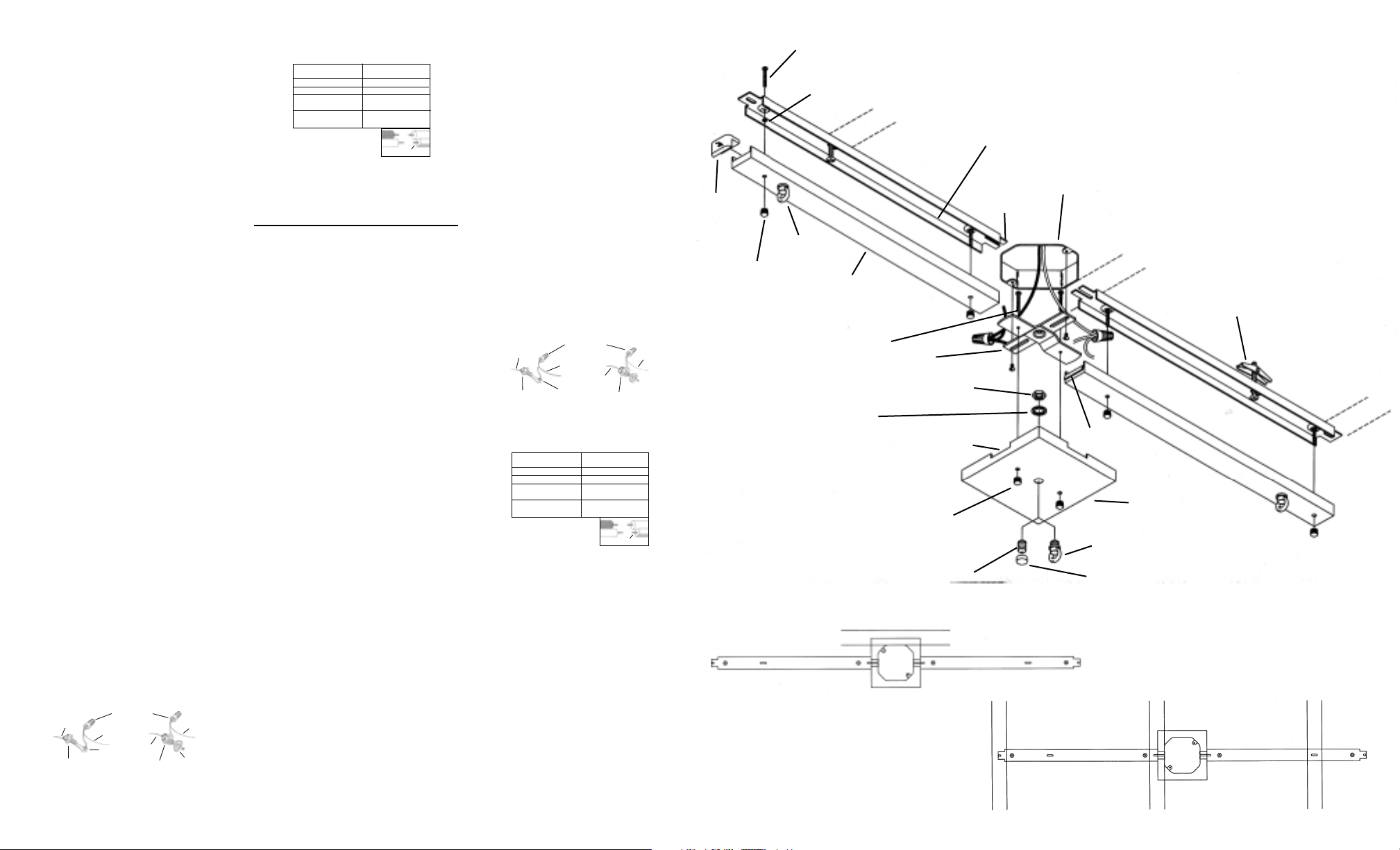
2) Assemble mounting screws into threaded holes
in mounting strap.
3) Attach mounting strap to outlet box.
4) Remove desired knockout(s) on canopy.
5) Assembly canopy to mounting strap. Knockouts
removed in step 4 should be facing desired
direction of arms.
6) Slide tab on back channel into knockout until
back channel is flush against canopy.
7) Mark position of mounting slots on ceiling
keeping the following in mind.
• If desired direction of arms is perpendicular
to ceiling joists, slots are spaced to allow
attachment to joists on 16" centers in either
direction. (REF. Illus. A)
• If desired direction of arms is parallel to ceiling
joists mark slot farthest from end of back
channel for use of anchors. (REF. Illus. B)
8) Temporarily remove canopy.
9) Drill appropriate pilot holes at positions marked
in step 7. If using provided anchors, 5/8" dia.
hole is required.
10) Assemble mounting screws to back channel
using hexnuts as illustrated.
11) Attach back channel to ceiling.
12) Assemble fixture following instructions provided
with fixtures. If fixture has glass, it should not
be assembled to fixture until installation is
complete.
13) Assemble loop to canopy using lockwasher
and hexnut. If no fixture will be suspended from
canopy, assemble threaded cap to canopy
using threaded pipe, lockwasher and hexnut.
14) For stem-mounted fixtures, screw provided
loop (with link of chain) to stem.
15) Pass wire from fixture through loop attached to
arm and/or canopy then connect chain or
chain link to loop.
16) Lift arm with fixture up to back channel making
sure fixture wire lays inside back channel and
insuring wire does not get pinched between
arm and back channel.
17) Secure arm in place with finials.
18) Grounding instructions: (See illus. Aor B)
A) On fixtures where mounting strap is provided
with a hole and two raised dimples. Wrap
ground wire from outlet box around green
ground screw, and thread into hole.
B)On fixtures where a cupped washer is
provided. Attach ground wire from outlet
box under cupped washer and green
ground screw, and thread into mounting
strap.
If fixture is provided with ground wire. Connect
fixture ground wire to outlet box ground wire
with wire connector. (Not provided)
19) Make wire connections (connectors not provided).
Reference chart below for correct connections
and wire accordingly.
20) Lift canopy up to ceiling and secure in place
with finials. Arms should be snug to outside of
canopy and the return on inside of canopy.
21) Push end caps into ends of arms.
22) Attach glass if required.
NOTA: EL USO PROYECTADO DE ESTE PRODUCTO ES SUSPENDER NO MÁS DE TRES
ARTEFACTOS. CADA ARTEFACTO NO DEBE
PESAR MÁS DE 15 LIBRAS.
1) Apague la alimentación eléctrica.
2) Ponga los tornillos de montaje en los agujeros
roscados, en la abrazadera de montaje.
3) Acople la abrazadera de montaje a la caja de
conexiones.
4) Quite los agujeros ciegos que quiera quitar en
el escudete.
5) Monte el escudete a la abrazadera de montaje.
Los agujeros ciegos que se quitaron en el paso
4 deben mirar en la dirección que desee que
miren los brazos.
6) Resbale la oreja en el perfil C posterior en el
agujero ciego hasta que el perfil C posterior
esté a ras con el escudete.
7) Marque la posición de las ranuras de montaje
en el cielo raso teniendo en cuenta lo siguiente:
•Si la dirección deseada de los brazos es
perpendicular a las viguetas del cielo raso,
las ranuras están espaciadas para permitir
el acople a las viguetas que están espaciadas
a 16" de centro a centro, en cualquiera de las
direcciones. (REF. Ilustración A)
•Si la dirección deseada de los brazos es
paralela a las viguetas del cielo raso, marque
la ranura más alejada del extremo del perfil C
posterior para usar los anclajes. (REF.
Ilustración B).
8) Quite el escudete temporalmente.
9) Perfore los agujeros auxiliares apropiados en
las posiciones marcadas en el paso 7. Si se
utiliza anclajes, se necesitan agujeros de 5/8"
de diámetro.
10) Ponga los tornillos de montaje en el perfil C
posterior usando las tuercas hexagonales
como se ilustró.
11) Monte el perfil C posterior al cielo raso.
12) Monte el artefacto siguiendo las instrucciones
que se proveen con los artefactos. Si el artefacto
tiene vidrio, el vidrio no debe montarse al
artefacto hasta que la instalación esté completa.
13) Monte el anillo al escudete usando la arandela
de seguridad y la tuerca hexagonal. Si el artefacto
no va a suspenderse del escudete, monte la
tapa roscada al escudete usando el tubo
roscado, la arandela de seguridad y la tuerca
hexagonal.
14) Para los artefactos montados del vástago,
atornille el anillo pro0visto (con eslabón de
cadena) al vástago.
LOOP
ANILLO
FINIAL
CAPUCHON
MOUNTING STRAP
ABRAZADE DE MONTAJE
RETURN
RETORNO
HEXNUT
TUERCA HEXAGONAL
THREADED CAP
TAPAROSCADA
THREADED PIPE
TUBO ROSCADO
CANOPY
ESCUDETE
KNOCKOUT
AGUJERO
CIEGO
LOCKWASHER
ARANDELA DE
SEGURIDAD
MOUNTING SCREW
TORNILLO DE MONTAJE
ARM
BRAZO
END CAP
TAPA
EXTREMA
LOOP
ANILLO
FINIAL
CAPUCHON
ANCHOR
ANCLAJE
OUTLET BOX
CAJA DE SALIDA
TAB
BORLA
BACK CHANNEL
PERFIL C POSTERIOR
STUD
ESPÁRRAGO
MOUNTING SCREW-
TORNILLO DE MONTAJE
HEXNUT
TUERCA
HEXAGONAL
15) Pase el cable del artefacto a través del anillo
acoplado al brazo y / o al escudete, luego
conecte la cadena o el eslabón de cadena al
anillo.
16) Levante el brazo con el artefacto arriba al perfil
C posterior cerciorán dose de que los cables
del artefacto estén dentro del perfil C posterior
y asegurándose de que no se pinchen entre
los brazos y en el perfil C posterior.
17) Sujete el brazo en el lugar con los capuchones.
18) Instrucciones de conexión a tierra solamente
para los Estados Unidos. (Vea la ilustracion Ao B).
A) En las lámparas que tienen el fleje, de montaje
con un agujero y dos hoyuelos realzados.
Enrollar el alambre a tierra de la caja
tomacorriente alrededor del tornillo verde y
pasarlo por el aquiero.
B) En las lámparas con una arandela acopada.
Fijar el alambre a tierra de la caja tomacorriente
del ajo de la arandela acoada y tornillo
verde, y paser por el fleje de montaje.
Si la lámpara viene con alambre a tierra.
Conecter el alambre a tierra de la lámpara al
alambre a tierra de la caja tomacorriente con
un conector de alambres (no incluido) espués
de seguir los pasos anteriores. Nunca conectar
el alambra a tierra a los alambres eléctros
negro o blanco.
19) Haga les conexiones de los alambres (no se
proveen los connectores.) La tabla de referencia
de abajo indica las conexiones correctas y los
alambres correspondientes.
20) Levante el escudete hasta el cielo raso y
sujete en el lugar con los capuchones. Los
brazos deben estar ajustados al exterior del
escudete y al retorno dentro del escudete.
21) Empuje las tapas extremas en los extremos de
los brazos.
22) Acople el vidrio si se necesita.
ILLUS. B
ILLUS. A
STUD
ESPÁRRAGO
IS-4900-US
Date Issued: 4/19/02
STUD
ESPÁRRAGO
A
OUTLET BOX
GROUND
GREEN GROUND
SCREW
FIXTURE
GROUND
DIMPLES
WIRE CONNECTOR
(NOT PROVIDED)
OUTLET BOX
GROUND
GREEN GROUND
SCREW
B
FIXTURE
GROUND
CUPPED
WASHER
Connect Black or
Red Supply Wire to:
Black White
*Parallel cord (round & smooth) *Parallel cord (square & ridged)
Clear, Brown, Gold or Black
without tracer
Insulated wire (other than green)
with copper conductor
*Note: When parallel wires (SPT I & SPT II)
are used. The neutral wire is square shaped
or ridged and the other wire will be round in
shape or smooth (see illus.)
Connect
White Supply Wire to:
Clear, Brown, Gold or Black
with tracer
Insulated wire (other than green)
with silver conductor
Neutral Wire
A
CONECTOR DE ALAMBRE
TIERRA DE LA
CAJA DE SALIDA
TORNILLO DE TIERRA,
VERDE
Conectar el alambre de
suministro negro o rojo al
*Cordon paralelo (redondo y liso)
Claro, marrón, amarillio o negro
sin hebra identificadora
Alambre aislado (diferente del verde)
con conductor de cobre
*Nota: Cuando se utiliza alambre paralelo
(SPT I y SPT II). El alambre neutro es de forma
cuadrada o estriada y el otro alambre será de
forma redonda o lisa. (Vea la ilustracíón).
(NO SE PROVEE)
TIERRA
ARTEFACTO
TIERRA DE LA
CAJA DE SALIDA
DEPRESIONES
Negro Blanco
*Cordon paralelo (cuadrado y estriado)
Claro, marrón, amarillio o negro
Alambre aislado (diferente del
verde) con conductor de plata
TORNILLO DE TIERRA,
VERDE
Conectar el alambre de
suministro blanco al
con hebra identificadora
Hilo Neutral
B
TIERRA
ARTEFACTO
 Loading...