

Page 1
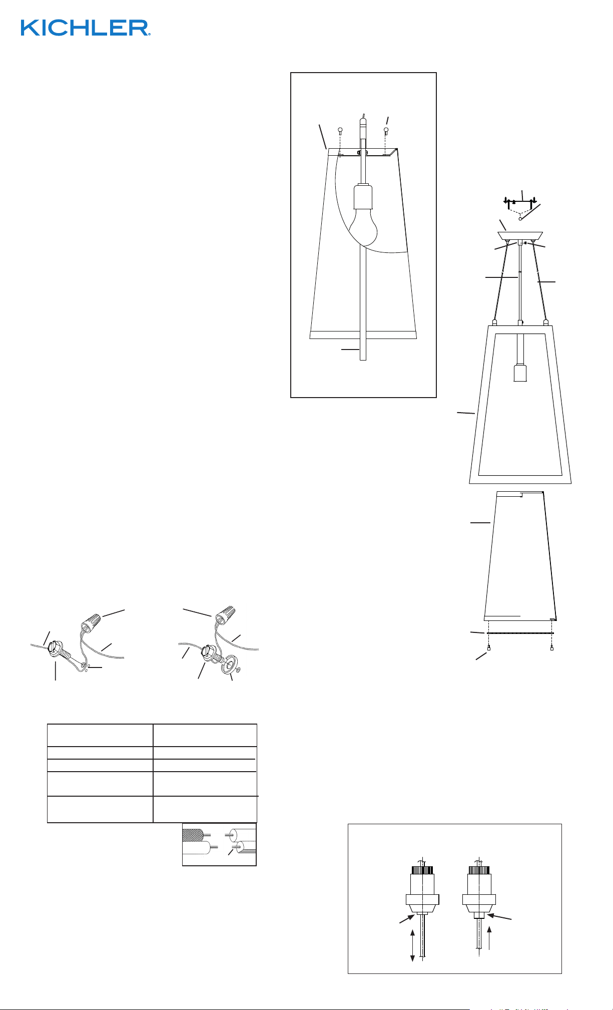
1) Fit shade in between frame of fixture.
2) Pass hole in top of shade over socket.
3) Raise shade up and set brackets on insides of shade on top
of brackets attached to fixture body.
4) Align holes in brackets on shade with holes in brackets of
fixture body.
5) Thread ball studs down through holes in brackets on shade
and into holes in brackets of fixture body. Tighten ball studs
to secure shade in place.
6) Adjust the length of the cables to achieve the desired height
of the mounted fixture. (See cable adjustment detail)
To raise fixture: Push cable up into canopy. Release cable
and cable will lock into place.
To lower fixture: Push button in on cable adjuster and pull
cable down. Release button to lock cable in place.
NOTE: With button pushed in cable will raise and lower.
Without button pushed in cable will only raise up and lock in
place.
7) Slip center cord from fixture through hole in short tube on
center of canopy. Match length of center cord with length of
cables. Thread set screw through hole on side of center
tube. Tighten set screw to secure center cord.
8) TURN OFF POWER.
IMPORTANT: Before you start, NEVER attempt any work
without shutting off the electricity until the work is done.
a) Go to the main fuse, or circuit breaker, box in your
home. Place the main power switch in the “OFF” position.
b) Unscrew the fuse(s), or switch “OFF” the circuit breaker
switch(s), that control the power to the fixture or room
that you are working on.
c) Place the wall switch in the “OFF” position. If the fixture
to be replaced has a switch or pull chain, place those in
the “OFF” position.
9) Find the appropriate threaded holes on mounting strap.
Assemble mounting screws into threaded holes.
10) Attach mounting strap to outlet box. (Screws provided).
Mounting strap can be adjusted to suit position of fixture.
11) Grounding instructions: (See Illus. A or B).
A) On fixtures where mounting strap is provided with a
hole and two raised dimples. Wrap ground wire from
outlet box around green ground screw, and thread into hole.
B) On fixtures where a cupped washer is provided. Attach
ground wire from outlet box under cupped washer and
green ground screw, and thread into mounting strap.
If fixture is provided with ground wire. Connect fixture
ground wire to outlet box ground wire with wire connector.
(Not provided.) After following the above steps. Never
connect ground wire to black or white power supply wires.
A
OUTLET BOX
GROUND
GREEN GROUND
SCREW
WIRE CONNECTOR
(NOT PROVIDED)
FIXTURE
GROUND
DIMPLES
OUTLET BOX
GROUND
GREEN GROUND
SCREW
B
CUPPED
WASHER
FIXTURE
GROUND
12) Make wire connections (connectors not provided.) Reference
chart below for correct connections and wire accordingly.
Connect Black or
Red Supply Wire to:
Black White
*Parallel cord (round & smooth)
Clear, Brown, Gold or Black
without tracer
Insulated wire (other than green)
with copper conductor
*Parallel cord (square & ridged)
Insulated wire (other than green)
Connect
White Supply Wire to:
Clear, Brown, Gold or Black
with tracer
with silver conductor
We’re here to help 866-558-5706
Hrs: M-F 9am to 5pm EST
BALL STUD
ESPÁRRAGO
SHADE
PANTALLA
FRAME
MARCO
SIDE VIEW
VISTA LATERAL
15) Insert recommended bulb.
16) Raise diffuser up to fixture. Align holes in diffuser with holes
in bracket on bottom of shade.
17) Thread ball studs up through holes in diffuser and into holes
in bracket on bottom of shade. Tighten ball studs to secure
shade in place.
NOTE: Adjust position of the fixture after installation for leveling
purposes of one inch or less. (See cable adjustment detail)
DE CABEZA
ESFÉRICA
MOUNTING STRAP
ABRAZADERA DE MONTAJE
CANOPY
ESCUDETE
SHORT TUBE
TUBO CORTO
CENTER
CORD
CORDÓN
DEL CENTRO
FRAME
MARCO
SHADE
PANTALLA
DIFFUSER
DIFUSOR
FINIAL
CAPUCHON
KNURL KNOB
PERILLA
ESTRADA
SET SCREW
TORNILLO DE
FIJACIÓN
CABLE
CABLE
*Note: When parallel wires (SPT I & SPT II)
are used. The neutral wire is square shaped
or ridged and the other wire will be round in
shape or smooth (see illus.)
Neutral Wire
13) Push fixture to ceiling, carefully passing mounting screws
through holes in canopy.
14) Thread knurl knobs onto mounting screws. Tighten knurl
knobs to secure fixture to ceiling.
SEE OTHER SIDE FOR SPANISH TRANSLATIONS.
VEA EL OTRO LADO DE TRADUCCIONES AL ESPAÑOL.
Date Issued: 9/27/13
CABLE ADJUSMENT DETAIL
EL DETALLE DE AJUSTE DEL CABLE
PRESSED
UP & DOWN
PRESSED
UP ONLY
NOT
IS-43361-US
Page 2
We’re here to help 866-558-5706
Hrs: M-F 9am to 5pm EST
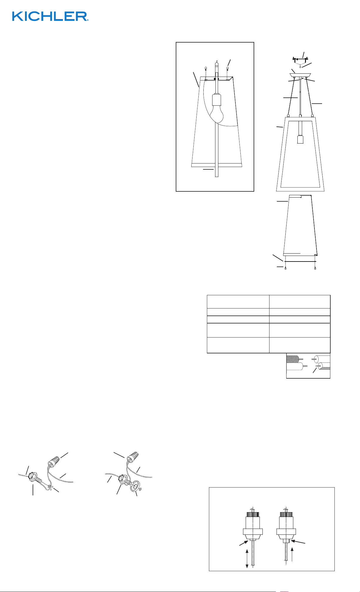
1) Ajuste la pantalla entre el marco del artefacto.
2) Pase el agujero en la parte superior de la pantalla sobre el
casquillo.
3) Levante la pantalla y coloque los soportes en el interior de la
pantalla encima de los soportes unidos al cuerpo del artefacto.
4) Alinee los agujeros en los soportes en la pantalla con los
agujeros en los soportes del cuerpo del artefacto.
5) Rosque los espárragos de cabeza esférica a través de los
agujeros en los soportes de la pantalla y en los agujeros en los
soportes del cuerpo del artefacto. Apriete los espárragos de
cabeza esférica para asegurar la pantalla en su lugar.
6) Ajuste la longitud de los 4 cables para lograr la altura de montaje
deseada del artefacto. (Vea los detalles de ajuste del cable.)
Para levantar el artefacto: Empuje el cable arriba en el escudete.
Suelte el cable y el cable se trabará en el lugar.
Para bajar el artefacto: Empuje el botón adentro en el ajustador
del cable y estire el cable hacia abajo. Suelte el botón para
trabar el cable en el lugar.
NOTA: Con el botón empujado adentro el cable se levantará y
bajará. Sin el botón empujado adentro el cable sólo se levanta y
se traba en el lugar. (VEA: EL DETALLE DE AJUSTE DEL CABLE.)
7) Deslice el cordón del centro desde el artefacto a través del
agujero en el tubo corto en el centro del escudete. Iguale la
longitud del cordón del centro con la longitud de los cables.
Rosque el tornillo de fijación a través del agujero en el lado del
tubo del centro. Apriete el tornillo de fijación para asegurar el
cordón del centro.
8) APAGUE LA ALIMENTACIÓN ELÉCTRICA.
IMPORTANTE: Antes de comenzar, NUNCA trate de trabajar
sin antes desconectar la corriente hasta que el trabajo se
termine.
a) Vaya a la caja principal de fusibles, o interruptor o caja
de circuitos de su casa. Coloque el interruptor de la
corriente principal en posición de apagado “OFF”.
b) Desatornille el (los) fusible (s), o coloque el interruptor o
interruptores del breaker en posición de apagado
“OFF”, que controla (n) la corriente hacia el artefacto o
habitación donde está trabajando.
c) Coloque el interruptor de pared en posición de apagado
“OFF”. Si el artefacto que se va a reemplazar tiene un
interruptor o cadena que se jala, colóquelos en la
posición de apagado “OFF”.
9) Encontrar los agujeros roscados correctos en la abrazadera
de montaje. Instalar los tornillos de montaje en los agujeros
roscados.
10) Unir la abrazadera de montaje a la caja de conexiones.
(tornillos suministrados). La abrazadera de montaje puede
ajustarse para acomodar la posición del artefacto.
11) Instrucciones de conexión a tierra solamente para los
Estados Unidos. (Vea la ilustracion A o B).
A) En las lámparas que tienen el fleje, de montaje con un
agujero y dos hoyue los realzados. Enrollar el alambre a
tierra de la caja tomacorriente alrededor del tornillo
verde y pasarlo por el aquiero.
B) En las lámparas con una arandela acopada. Fijar el
alambre a tierra de la caja tomacorriente del ajo de la
arandela acoada y tornillo verde, y paser por el fleje de
montaje.
Si la lámpara viene con alambre a tierra. Conecter el
alambre a tierra de la lámpara al alambre a tierra de la caja
tomacorriente con un conector de alambres (no incluido)
espués de seguir los pasos anteriores. Nunca conectar el
alambra a tierra a los alambres eléctros negro o blanco.
A
TIERRA DE LA
CAJA DE SALIDA
TORNILLO DE TIERRA,
VERDE
CONECTOR DE ALAMBRE
(NO SE PROVEE)
TIERRA
ARTEFACTO
DEPRESIONES
CAJA DE SALIDA
TIERRA DE LA
TORNILLO DE TIERRA,
VERDE
B
TIERRA
ARTEFACTO
ARANDELA
CONCAVA
BALL STUD
ESPÁRRAGO DE
CABEZA ESFÉRICA
SHADE
PANTALLA
SHORT TUBE
TUBO CORTO
DEL CENTRO
FRAME
MARCO
FRAME
MARCO
SIDE VIEW
VISTA LATERAL
SHADE
PANTALLA
DIFFUSER
DIFUSOR
FINIAL
CAPUCHON
MOUNTING STRAP
ABRAZADERA DE MONTAJE
CANOPY
ESCUDETE
CENTER
CORD
CORDÓN
KNURL KNOB
PERILLA
ESTRADA
SET SCREW
TORNILLO DE
FIJACIÓN
CABLE
CABLE
12) Haga les conexiones de los alambres (no se proveen los
connectores.) La tabla de referencia de abajo indica las
conexiones correctas y los alambres correspondientes.
Conectar el alambre de
suministro negro o rojo al
Negro Blanco
*Cordon paralelo (redondo y liso)
Claro, marrón, amarillio o negro
sin hebra identificadora
Alambre aislado (diferente del verde)
con conductor de cobre
*Nota: Cuando se utiliza alambre paralelo
(SPT I y SPT II). El alambre neutro es de forma
cuadrada o estriada y el otro alambre será de
forma redonda o lisa. (Vea la ilustracíón).
Conectar el alambre de
suministro blanco al
*Cordon paralelo (cuadrado y estriado)
Claro, marrón, amarillio o negro
con hebra identificadora
Alambre aislado (diferente del
verde) con conductor de plata
Hilo Neutral
13) Empuje el artefacto hacia el techo, pasando cuidadosamente
los tornillos de montaje a través de los orificios en el escudete.
14) Atornille las perillas estriadas en los tornillos de montaje.
Ajuste las perillas estriadas para fijar el artefacto en el techo.
15) Coloque el foco recomendado.
16) Levante el difusor hasta el artefacto. Alinee los agujeros
en el difusor con los agujeros en el soporte en la parte
inferior de la pantalla.
17) Rosque los espárragos de cabeza esférica a través de los
agujeros en el difusor y en los agujeros en el soporte en la
parte inferior de la pantalla. Apriete los espárragos de
cabeza esférica para asegurar la pantalla en su lugar.
NOTA: Ajuste de la posición del artefacto después de la
instalación con el propósito de nivelar una pulgada o menos.
VEA: EL DETALLE DE AJUSTE DEL CABLE.)
CABLE ADJUSMENT DETAIL
EL DETALLE DE AJUSTE DEL CABLE
SEE OTHER SIDE FOR ENGLISH TRANSLATIONS.
VEA EL OTRO LADO DE TRADUCCIONES AL INGLÉS.
Date Issued: 9/27/13
PRESSED
UP & DOWN
NOT
PRESSED
UP ONLY
IS-43361-US
 Loading...