

Page 1
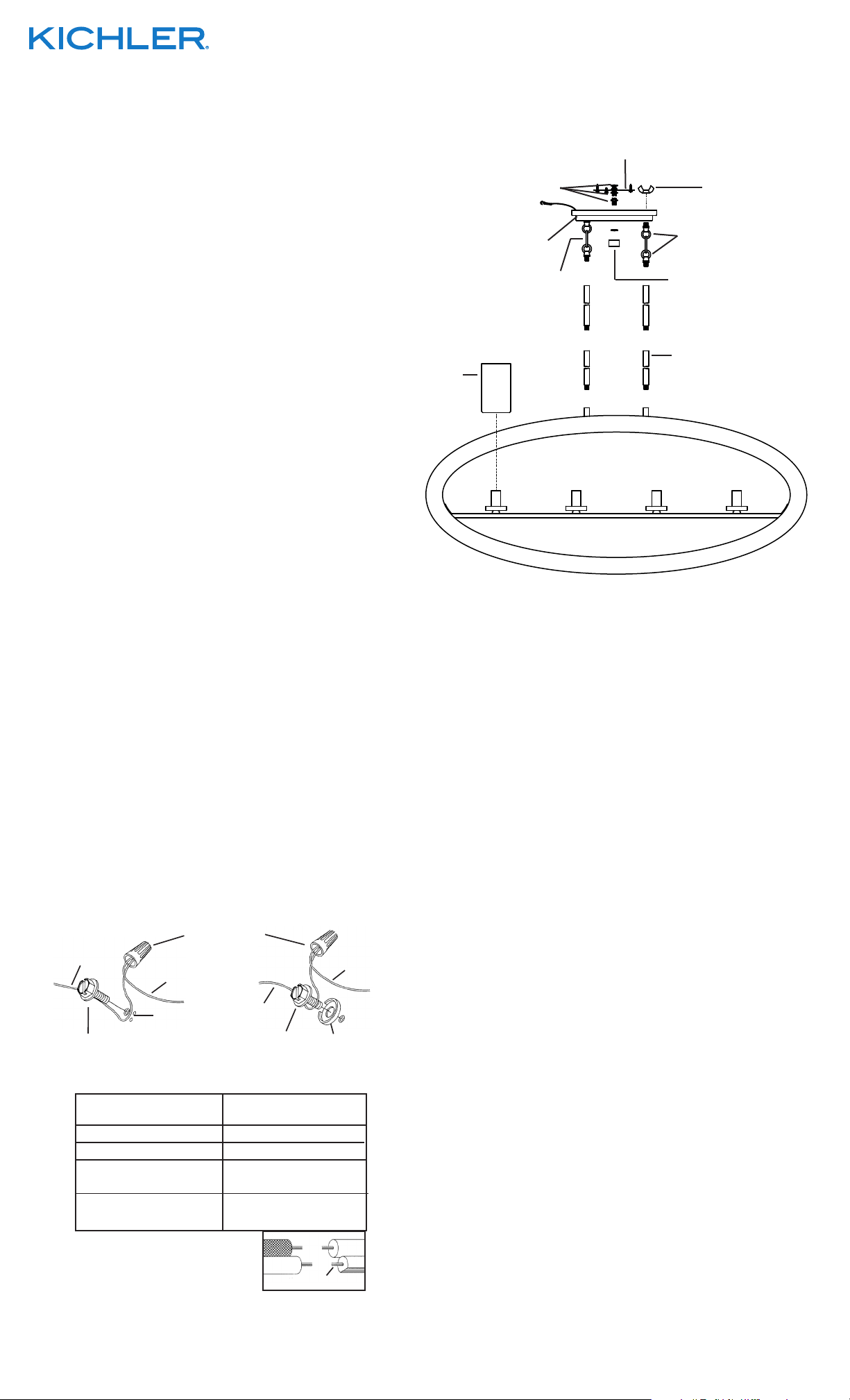
1) Pass wire from fixture through stems and screw stems into
SCREW
A
couplings on top of fixture body.
NOTE: Thread locking compound must be applied to all stem
threads as noted with symbol (3) to prevent accidental
rotation of fixture during cleaning, relamping, etc.
2) Pass fixture wire through remaining stems and screw stems
together.
3) The canopy has one set of loop/chain link/loop pre-installed.
Starting with that loop/chain link/loop, pass fixture wire
through the threaded pipe on the first small loop. Next pass
the fixture wire through the hole in the small loop attached to
canopy and through the hole in the canopy.
4) With the set of loop/chain link/loop not pre-installed, from the
second set of stems, pass the fixture wire through the hole in
the threaded pipe on the end of one small loop. Thread that
small loop to the end of the last stem.
5) Pass fixture wire through hole in second small loop. Pass
fixture wire through hole in canopy. Pass threaded pipe at end
of second loop through hole in canopy. Thread wing nut onto
end of threaded pipe. Tighten wing nut to secure loop to canopy.
6) TURN OFF POWER.
IMPORTANT: Before you start, NEVER attempt any work
without shutting off the electricity until the work is done.
a) Go to the main fuse, or circuit breaker, box in your home.
Place the main power switch in the “OFF” position.
b) Unscrew the fuse(s), or switch “OFF” the circuit breaker
switch(s), that control the power to the fixture or room that
you are working on.
c) Place the wall switch in the “OFF” position. If the fixture to
be replaced has a switch or pull chain, place those in the
“OFF” position.
7) Thread hexnut onto threaded pipe so that 5 threads are
exposed above hexnut. Thread that end of threaded pipe
into mounting strap and tighten hexnut against mounting strap.
8) Run another hexnut down threaded pipe almost touching
first hexnut. Now screw threaded pipe into mounting strap.
Mounting strap must be positioned with extruded thread
faced into outlet box. Threaded pipe must protrude out the
back of mounting strap. Screw third hexnut onto end of
threaded pipe protruding from back of mounting strap.
9) Attach mounting strap to outlet box. (Screws not provided.)
10) Attach safety cable to slot in mounting strap.
11) Grounding instructions: (See Illus. A or B).
A) On fixtures where mounting strap is provided with a hole
and two raise dimples. Wrap ground wire from outlet box
around green ground screw, and thread into hole.
B) On fixtures where a cupped washer is provided. Put
ground wire from outlet box under cupped washer and
green ground screw and thread screw into hole in mounting
strap.
If fixture is provided with ground wire. Connect fixture ground
wire to outlet box ground wire with wire connector, (not
provided) after following the above steps. Never connect
ground wire to black or white power supply wires.
B
WIRE CONNECTOR
FIXTURE
GROUND
DIMPLES
(NOT PROVIDED)
OUTLET BOX
GROUND
GREEN GROUND
SCREW
FIXTURE
GROUND
CUPPED
WASHER
OUTLET BOX
GROUND
GREEN GROUND
12) Make wire connections (connectors not provided.) Reference
chart below for correct connections and wire accordingly.
Connect Black or
Red Supply Wire to:
Black White
*Parallel cord (round & smooth)
Clear, Brown, Gold or Black
without tracer
Insulated wire (other than green)
with copper conductor
*Parallel cord (square & ridged)
Insulated wire (other than green)
Connect
White Supply Wire to:
Clear, Brown, Gold or Black
with tracer
with silver conductor
We’re here to help 866-558-5706
Hrs: M-F 9am to 5pm EST
MOUNTING STRAP
PLANCHA PARA MONTAR
HEXNUT
TUERCA HEXAGONAL
SAFETY CABLE
CABLE DE SEGURIDAD
CANOPY
WING NUT
TUERCA DE MARIPOSA
SMALL LOOP
ARGOLLA PEQUEÑA
ESCUDETE
CHAIN LINK
ESLABÓN DE
4
FINIAL
REMATE
CADENA
3
STEM
GLASS
VIDRIO
13) Push fixture to ceiling, carefully passing threaded pipe through
hole in canopy.
14) Thread hexnut onto end of threaded pipe protruding from
canopy. Tighten hexnut up against canopy.
15) Thread finial onto end of threaded pipe. (DO NOT over tighten.)
16) Set glass down over sockets.
VARILLA
3
*Note: When parallel wires (SPT I & SPT II)
are used. The neutral wire is square shaped
or ridged and the other wire will be round in
shape or smooth (see illus.)
Date Issued: 7/25/14
Neutral Wire
SEE OTHER SIDE FOR SPANISH TRANSLATIONS.
VEA EL OTRO LADO DE TRADUCCIONES AL ESPAÑOL.
IS-43191-US
Page 2
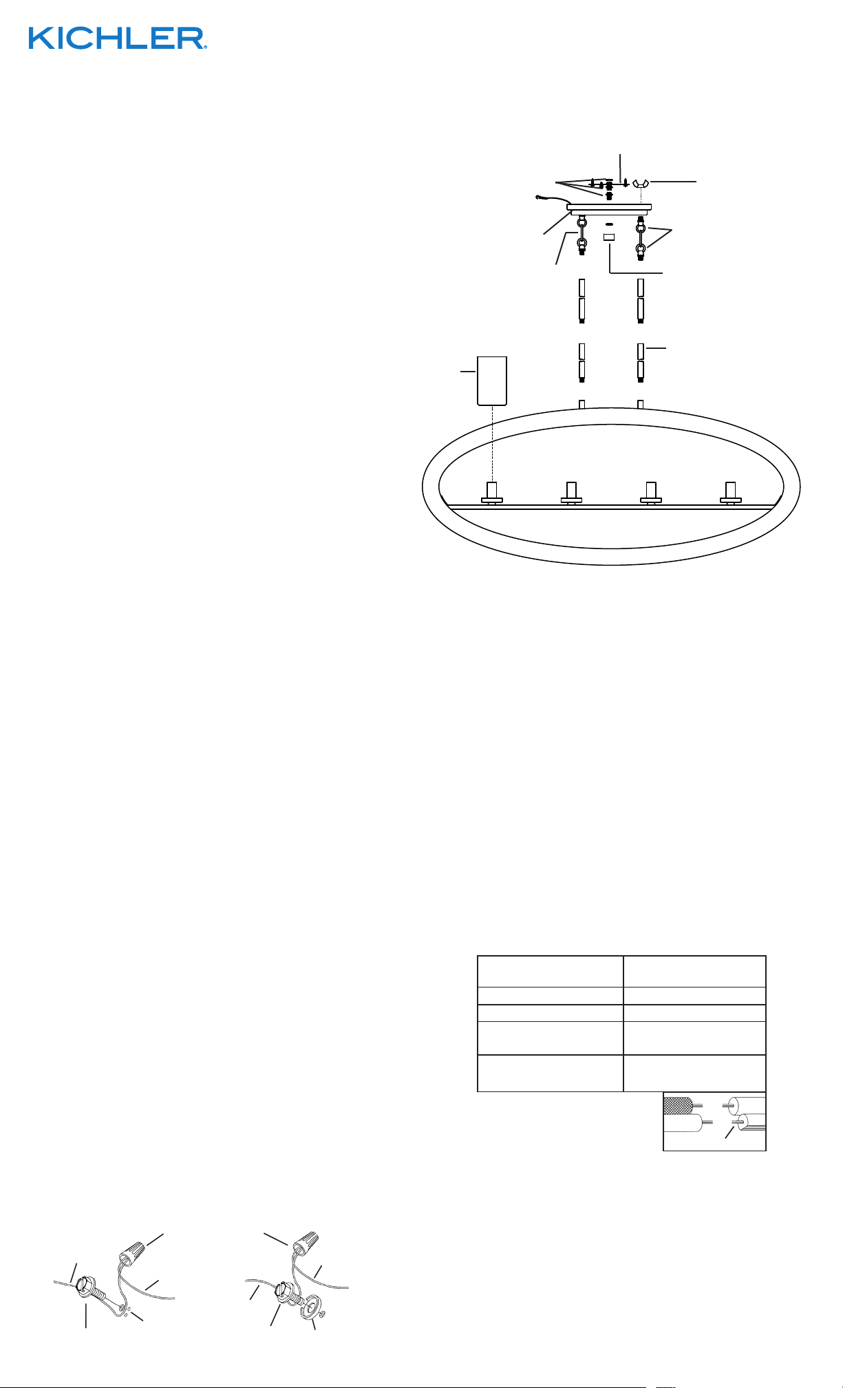
1) Pase el alambre del artefacto a través del vástago y atornille el
CONCAVA
A
B
VERDE
vástago en el acoplamiento en la parte superior del el cuerpo
del artefacto. NOTA: El compuesto para rosca estanca se debe
aplicar a todas las roscas del vástago como se notó con el
símbolo (3) para impedir la rotación accidental del artefacto
durante la limpieza, instalación de una bombilla nueva, etc.
2) Pase el alambre del artefacto a través de los vástagos restantes
y atornille los vástagos juntos.
3) El escudete tiene un conjunto de anillo / eslabón de cadena /
anillo pre-instalados. Empezando con ese anillo / eslabón de
cadena / anillo, pase el alambre del artefacto a través del tubo
roscado en el primer anillo pequeño. Después pase el alambre
del artefacto a través del agujero en el anillo pequeño sujeto al
escudete y a través del agujero en el escudete.
4) Con el conjunto de anillo / eslabón de cadena / anillo sin
instalación previa, desde el segundo conjunto de vástagos,
pase el alambre del artefacto a través del agujero en el tubo
roscado en el extremo de un anillo pequeño. Enrosque ese
anillo pequeño en el segundo anillo pequeño al extremo del
último vástago.
5) Pase el alambre del artefacto a través del agujero en el
segundo anillo pequeño. Pase el alambre del artefacto a
través del agujero en el escudete. Pase el tubo roscado en el
extremo del segundo anillo a través del agujero en el
escudete. Enrosque la tuerca de mariposa sobre el extremo
del tubo roscado. Apriete la tuerca de mariposa para asegurar
el anillo al escudete.
6) APAQUE EL SUMINITRO DE POTENCIA.
IMPORTANTE: Antes de comenzar, NUNCA trate de trabajar
sin antes desconectar la corriente hasta que el trabajo se
termine.
a) Vaya a la caja principal de fusibles, o interruptor o caja de
circuitos de su casa. Coloque el interruptor de la corriente
principal en posición de apagado “OFF”.
b) Desatornille el (los) fusible (s), o coloque el interruptor o
interruptores del breaker en posición de apagado “OFF”,
que controla (n) la corriente hacia el artefacto o habitación
donde está trabajando.
c) Coloque el interruptor de pared en posición de apagado
“OFF”. Si el artefacto que se va a reemplazar tiene un
interruptor o cadena que se jala, colóquelos en la posición
de apagado “OFF”.
7) Atornille la tuerca hexagonal en el tubo roscado de manera
que 5 roscas estén expuestas arriba de la tuerca hexagonal.
Rosque ese extremo del tubo roscado en la abrazadera de
montaje y apriete la tuerca hexagonal contra la abrazadera
de montaje.
8) Instale otra tuerca hexagonal en el tubo roscado casi
tocando la primera tuerca hexagonal. Ahora, atornille el tubo
roscado en la abrazadera de montaje. La abrazadera de
montaje se debe colocar con la rosca extruida mirando
hacia la caja de salida. El tubo roscado debe sobresalir
atrás de la abrazadera de montaje. Atornille la tercera tuerca
hexagonal en el extremo del tubo roscado que sobresale de
la parte posterior de la abrazadera de montaje.
9) Una la barra de montaje a la caja de salida. (no se suministran
los tornillos).
10) Acople la activación de seguridad en la ranura de la barra de
montaje.
11) Instrucciones de puesta a tierra: (Vea la ilustración A o B)
A) En los artefactos donde se proporciona la abrazadera de
montaje con un agujero y dos depresiones elevadas.
Envuelva el alambre a tierra de la caja de salida alrededor
del tornillo a tierra verde y rosque el tornillo en el agujero.
B) En los artefactor donde se proporciona una arandela
cóncava. Ponga el alambre a tierra de la caja de salida
entre la arandela cóncava y el tornillo a tierra verde y
rosque el tornillo en el agujero, en la abrazadera de
montaje.
Si se proporciona el artefacto con alambre a tierra, conecte el
alambre a tierra del artefacto al alambrea a tierra de la caja de
salida, con el conector de alambre (no proporcionado),
después de seguir los pasos de arriba. Nunca conecte el
alambre a tierra a los alambres blanco o negro de la alimentación
eléctrica.
CONECTOR DE ALAMBRE
TIERRA DE LA
CAJA DE SALIDA
(NO SE PROVEE)
TIERRA
ARTEFACTO
TIERRA
ARTEFACTO
We’re here to help 866-558-5706
Hrs: M-F 9am to 5pm EST
MOUNTING STRAP
PLANCHA PARA MONTAR
HEXNUT
TUERCA HEXAGONAL
SAFETY CABLE
CABLE DE SEGURIDAD
CANOPY
WING NUT
TUERCA DE MARIPOSA
SMALL LOOP
ARGOLLA PEQUEÑA
ESCUDETE
CHAIN LINK
ESLABÓN DE
4
FINIAL
REMATE
CADENA
3
STEM
GLASS
VIDRIO
12) Hacer las conexiones de los alambres (conectores no incluidos.)
Ver el cuadro más abajo para las conexiones correctas y
alambrar de acuerdo a esto.
Conectar el alambre de
suministro negro o rojo al
Negro Blanco
*Cordon paralelo (redondo y liso)
Claro, marrón, amarillio o negro
sin hebra identificadora
Alambre aislado (diferente del verde)
con conductor de cobre
*Nota: Cuando se utiliza alambre paralelo
(SPT I y SPT II). El alambre neutro es de forma
cuadrada o estriada y el otro alambre será de
forma redonda o lisa. (Vea la ilustracíón).
13) Empuje el artefacto contra el techo, pasando cuidadosamente
el tubo roscado a través del orificio en el escudete.
14) Deslice la tuerca hexagonal sobre el extremo del tubo roscado
que sobresale del escudete. Apriete el tuerca hexagonal
contra el escudete.
15) Enrosque el remate decorativo en el extremo del tubo roscado.
(NO apriete excesivamente.)
16) Coloque la vidrio abajo encima del casquillo.
VARILLA
3
Conectar el alambre de
suministro blanco al
*Cordon paralelo (cuadrado y estriado)
Claro, marrón, amarillio o negro
con hebra identificadora
Alambre aislado (diferente del
verde) con conductor de plata
Hilo Neutral
TORNILLO DE TIERRA,
Date Issued: 7/25/14
DEPRESIONES
TIERRA DE LA
CAJA DE SALIDA
TORNILLO DE TIERRA,
VERDE
ARANDELA
SEE OTHER SIDE FOR ENGLISH TRANSLATIONS.
VEA EL OTRO LADO DE TRADUCCIONES AL INGLÉS.
IS-43191-US
 Loading...