

Page 1
READ AND SAVE THESE INSTRUCTIONS
Universal CoolTouch™ Control System
337214
U.S. Patent Pending
ATTENTION: This control system was designed to operate and work with a wide range of
Kichler® Ceiling Fans. It is also compatible with "most" ceiling fan brands on the market.
However, it is possible that some brands of ceiling fans will not be compatible with this control
system. Please consult your Kichler® Dealer with any compatibility questions
Page 2
1
ON ECE
1 2 3 4
ON
D
GENERAL INFORMATION
The Universal CoolTouch™ Control System is designed for Indoor or
Outdoor use. It will separately control your Ceiling Fan Speeds and the
Light Fixture (if equipped). This control system does NOT remotely control
the forward/reverse function.
Transmitter Control Buttons
● Speed Settings Low - Medium - High
● Motor Off
● Light Fixture, On/Off
1. INSTALLATION AND SET-UP:
Press Here
Code switches
The Universal CoolTouch™ Control System is a RF (Radio Frequency)
remote control with adjustable frequencies.
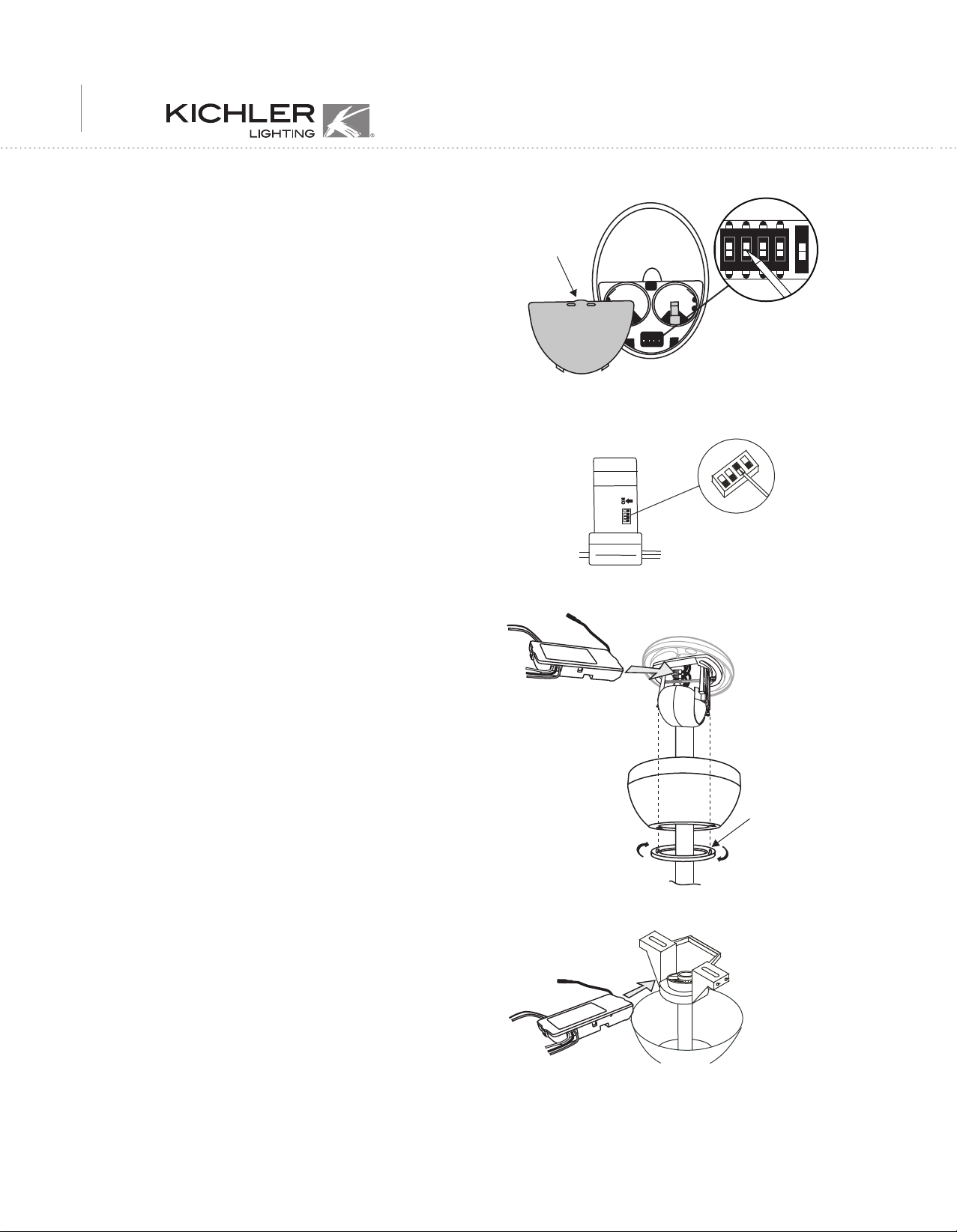
The Frequency Selector is a "Dip Switch Block" inside the Battery
compartment of the Transmitter (see figure A) and on the Receiver Unit (see
figure B). You change frequencies by arranging the small switches
numbered 1 through 4 in a up or down position.
1. SETTING THE OPERATIONAL FREQUENCY:
A. Setting the Transmitter Frequency:
a. Remove the battery cover on the back of the transmitter by pressing on
the cover lid at the point indicated in Figure A.
b. Arrange the “Dip Switches” 1 through 4 in any order you wish (up or
down)
c. If your fan is equipped with a Light Fixture, the fifth switch, marked D
and ON sets the system for operation with Incandescent or Fluorescent
Lamps. It is essential to set this switch correctly or you could damage
the lamps and/or fixture.
i. Incandescent Lamps = Set the switch to D
ii. Fluorescent Lamps = Set the switch to ON
d. Use a small flat bladed screw driver to move the switches.
B. Setting the Receiver Frequency:
a. The Frequency Selector on the Receiver is located under a rubber plug
on top of the receiver and has only four switches ( 1 through 4 ).
b. Remove the rubber plug and match the position of each switch on the
Receiver to the same position on the Transmitter. This sets both the
Receiver & Transmitter to the same frequency.
c. Replace the rubber plug. This will keep water and moisture out of the
receiver unit.
Transmitter
Fig. A
ON
Code switches
Receiver
Fig. B
RECEIVER
Mounting Screw
Cover
2. INSTALLING THE RECEIVER
WARNING: HIGH VOLTAGE ! Household electrical power can cause
serious injury or death. Make sure the electrical power source is turned OFF
at the main panel by removing the circuit fuse or switching the circuit
breaker OFF.
A. Installing the receiver unit:
a. Rotate the mounting screw cover on the canopy counter clockwise,
loosen the two mounting screws, rotate the canopy counter clockwise and
let them rest on top of the motor housing.
b. Disconnect the existing electrical wiring between the ceiling
fan and the household supply wires in the ceiling outlet box.
c. Slide the receiver unit into the open space between the top of
the mounting bracket and the mounting ball with the "flat"
side of the receiver facing UP. (Fig. C or D)
The CoolTouch™ Receiver Unit is adaptable to the Kichler
Mounting System (Fig. D) as well as the Kichler
®
Slope Adaptor Mounting
System (Fig. C)
®
Basic
Fig. C
RECEIVER
Fig. D
Page 3

CoolTouchTM control system
2
AC SUPPLY
WHITE
WHITE
RECEIVER
OUTLET BOX
BLACK
BLACK
BLUE BLUE
BLACK
WHITE
BARE
BLACK
WHITE
Fig. E
GREEN
Receiver to Supply Wires: Figure E
Green fan wire to...............................Green or copper Household supply wire
Black receiver wire marked AC In L to........ Black Household supply wire
White receiver wire marked AC In N to........White Household supply wire
Receiver to Fan wires: Figure E
White receiver wire marked TO MOTOR N to..............White wire from the Fan
Black receiver wire marked TO MOTOR L to...............Black wire from the Fan
Blue receiver wire marked FOR LIGHT to.....................Blue wire from the Fan
CAUTION: If the household supply wires are a different color
than described here, it's recommended that you have a qualified
electrician make these connections.
d. Push all connected wires up into junction box.
e. Reinstall the canopy on the mounting bracket. (Fig. C)
3. OPERATING INSTRUCTIONS
The Universal CoolTouch™ Transmitter can be used outdoors
without any concern. However, it should be mounted indoors away
from excess heat and not allowed to come into contact with water or
excess humidity.
A. Remove the back cover on the transmitter and install both, 3 volt
(#2032) batteries that were included with the remote control. Make
sure the + sign is facing up and be careful NOT to move any of the
small frequency dip switches. (Fig. F)
Fig. F
Fig. G
Replace the battery cover.
B: To prevent possible damage to the transmitter, remove these
batteries if not used for long periods of time (months).
C. ●, ●●, ●●● Buttons:
These Buttons are used to set the fan speed as follows:
●●●
= Low Speed
●● = Medium Speed
● = High Speed
B. " " Button:
This button turns the fan motor off.
The " " Button:
Incandescent Lamps - Press and Release for On/Off - Press and HOLD for
Full Range Dimming, release at the desired brightness level. You can turn
the lamps On and Off at any level.
Fluorescent Lamps - Press and Release for On/Off. The Dimming function
is disabled for fluorescent lamps.
Page 4

3
4. INSTALLING THE COOLTOUCH™
CONTROL SYSTEM WALL PLATE
Select a location to install the Universal CoolTouch™ Control System
Transmitter and Wall Pocket.
RMEMEBER, you can safely use the transmitter outdoors but it should be
mounted indoors away from excess heat and away from contact with water
or humidity.
You can replace an existing wall switch or, install the transmitter wall
pocket on ANY flat surface.
NOTE: The Wall Pocket should be installed with the "Release Button" on
the TOP of the pocket.
Option 1: Install the wall pocket using an existing wall switch outlet box.
Make sure the electrical power is TURNED OFF at the main panel before
continuing.
Step 1. Remove the existing wall plate and the old switch from the wall
outlet box. Wire nut the BLACK leads (hot) together and push back inside
the outlet box. (Fig. H)
Step 2. Install the metal plate and CoolTouch™ Wall Pocket on the existing
wall outlet box using the four screws provided. then place the two plastic
plugs into the wall plate. NOTE: The small plug goes in the TOP hole. (see
figure I)
Option 2: Install the wall pocket on ANY flat surface. Select the desired
location and use the CootTouch™ wall pocket to mark the location for the
mounting holes. Plastic wall anchors and screws are provided for this type
of installation.
Outlet box
Outlet box
Metal plate
Screws
Switch
Wall plate
Fig. H
CoolTouch™ wall pocket
Plastic plugs
Screws
After installing the wall anchors, attached the CoolTouch™ wall pocket with
the mounting screws and then insert the plastic plugs to finish the
installation.
5. STORING THE TRANSMITTER
Place the transmitter in the wall pocket by inserting the bottom of the
transmitter first and then press the top of the transmitter into the pocket.
The transmitter will fully function from this location or you can remove
it to use as a "Hand Held" device.
To remove the transmitter from the wall pocket, push the release button
and the transmitter will fall into your hand.
6. TROUBLESHOOTING GUIDE
If the Ceiling Fan and or light fixture(s) fail to respond to commands from
the transmitter, check the following.
● Check the main power supply and reset or turn on the breaker.
● Make sure the "Receiver Unit" is wired properly.
● Light Fixture pull chain switch turned to ON ?
● Good batteries in transmitter ? Replace if needed.
● Transmitter and Receiver "frequency" switches set to match each
other ?
NOTE: The distance between the transmitter and receiver should not be
greater than 30 feet. For best performance, make sure the Black Antenna on
the end of the receiver unit remains extended and not tangled with any of the
electrical wires.
Fig. I
Release
button
Fig. J
WARNING: This control system is intended for use on 120 volt / 60
Hz power systems ONLY.
 Loading...