

Page 1
Kichler® Lighting
7711 East Pleasant Valley Road
P.O. Box 318010
Cleveland, Ohio 44131-8010
Customer Service
866.558.5706
8:30 AM to 5:00 PM EST,
Monday - Friday
TM
Meredith
A Kichler® Décor™ ceiling fan
Designed to coordinate with a popular Kichler Lighting collection.
Includes our new
CoolTouchTM Control System
Looks permanent, but goes wherever you go!
U.S. Patent Pending
Instruction Manual
KHA9090103
Page 2
1
1. SAFETY RULES
1. To reduce the risk of electric shock, insure
electricity has been turned off at the circuit
breaker or fuse box before cleaning and
maintenace, or attempting Installation.
2.
All wiring must be in accordance with the
National Electrical Code, ANSI/NFPA70-1999
and local electrical codes. Electrical installation should be performed by a qualified
licensed electrician.
3. WARNING: To reduce the risk of electrical
shock and fire, do not use this fan with
any solid-state fan speed control device.
WARNING: To reduce the risk of fire,
4.
electric shock, or personal injury, mount
this fan to outlet box marked "Acceptable
for Fan Support" and use mounting
screws provided with the outlet box. Most
outlet boxes commonly used for the support of light fixtures are not acceptable for
fan support and may need to be replaced.
Due to the complexity of the installation of
this fan, a qualified licensed electrician is
strongly recommended.
WARNING
TO REDUCE THE RISK OF FIRE, ELECTRIC
SHOCK OR PERSONAL INJURY, MOUNT FAN TO
OUTLET BOX MARKED "ACCEPTABLE FOR FAN
SUPPORT."
8. Avoid placing objects in the path of the
blades.
9. To avoid personal injury or damage to the
fan and other items, be cautious when
working around or cleaning the fan.
10. Do not use water or detergents when
cleaning the fan or fan blades. A dry dust
cloth or lightly dampened cloth will be
suitable for most cleaning.
11. After marking electrical connections,
spliced conductors should be turned
upward and pushed carefully up into outlet
box. The wires should be spread apart with
conductor of a fan identified as grounded
condutor to be connected to a grounded
conductor of power supply, conductor of fan
identified as ungrounded conductor to be
connected to an ungrounded conductor of
power supply,conductor of fan identified for
equipment grounding to be connected to an
equipment-grounding conductor.
12. Electrical diagrams are for reference only.
Light kits that are not packed with the fan
must be marked suitable for use with the
model fan you are installing. Refer to the
Instructions packaged with the light kits and
switches for proper assembly.
5. The outlet box and support structure must
be securely mounted and capable of
reliably supporting a minimum of 50
pounds. Use the outlet boxes marked
"FOR FAN SUPPORT."
6. The fan must be mounted with a minimum
of 7 feet clearance from the trailing edge of
the blades to the floor.
7. To operate the reverse function on this fan,
press the reverse button while the fan is
running.
WARNING
TO REDUCE THE RISK OF PERSONAL INJURY,
DO NOT BEND THE BLADE BRACKETS WHEN
INSTALLING THE BRACKETS, BALANCING THE
BLADES, OR CLEANING THE FAN. DO NOT
INSERT FOREIGN OBJECTS IN BETWEEN ROTATING FAN BLADES.
Page 3
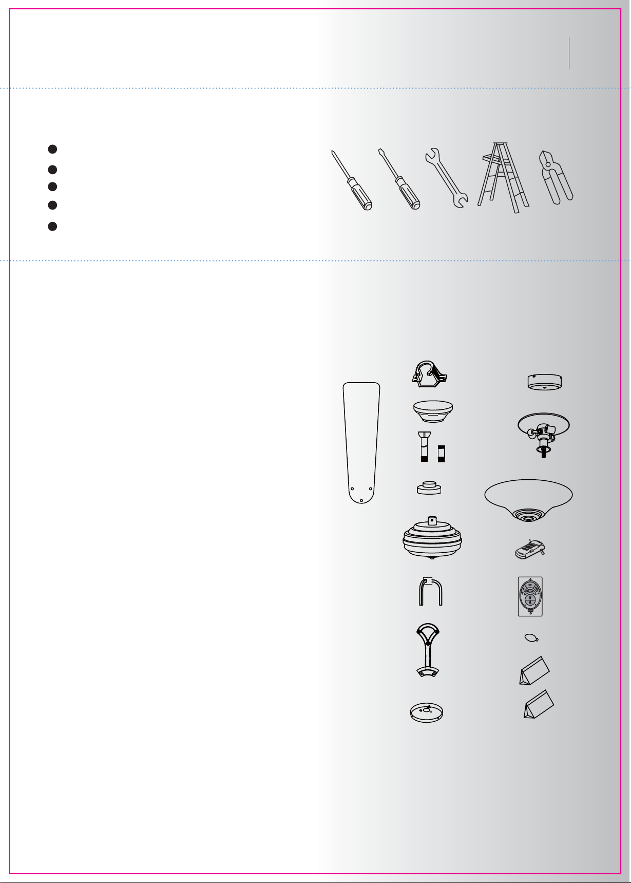
2. TOOLS AND MATERIALS REQUIRED
Philips screw driver
Slot screw driver
11 mm wrench
Step ladder
Wire cutters
3. PACKAGE CONTENTS
Unpack your fan and check the contents. You
should have the following items:
a. Fan blades (5)
b. Mounting bracket
c. Canopy
d. Ball/downrod assembly (1)
& extra downrod (1)
e. Coupling cover
f. Fan assembly
g. Decorative arm
h. Set of blade brackets (5)
i. Mounting plate
j. Switch housing
k. Light kit
l. Glass bowl
m. Receiver +7 wire nuts
n. CoolTouch™ Control System
o. Bulbs (3)
p. Package hardware:
1) Mounting hardware:
a. wood screws (2), flat washers(2),
screws(2), wire nuts(4)
2) Blade attachment hardware:
a. screws (16); flat washers(16);
fiber washers(16)
3) Blade bracket hardware:
a. screws (1)
4) Safety cable hardware:
a. wood screw (1); spring washer (1);
flat washer (1)
5) Balance kit
q. Decorative plate hardware:
a. decorative plate (1); finial (1);
light kit hardware (1)
TM
Meredith
b
2
j
c
a
k
d
e
l
f
m
g
h
n
o
p
q
i
Page 4
3
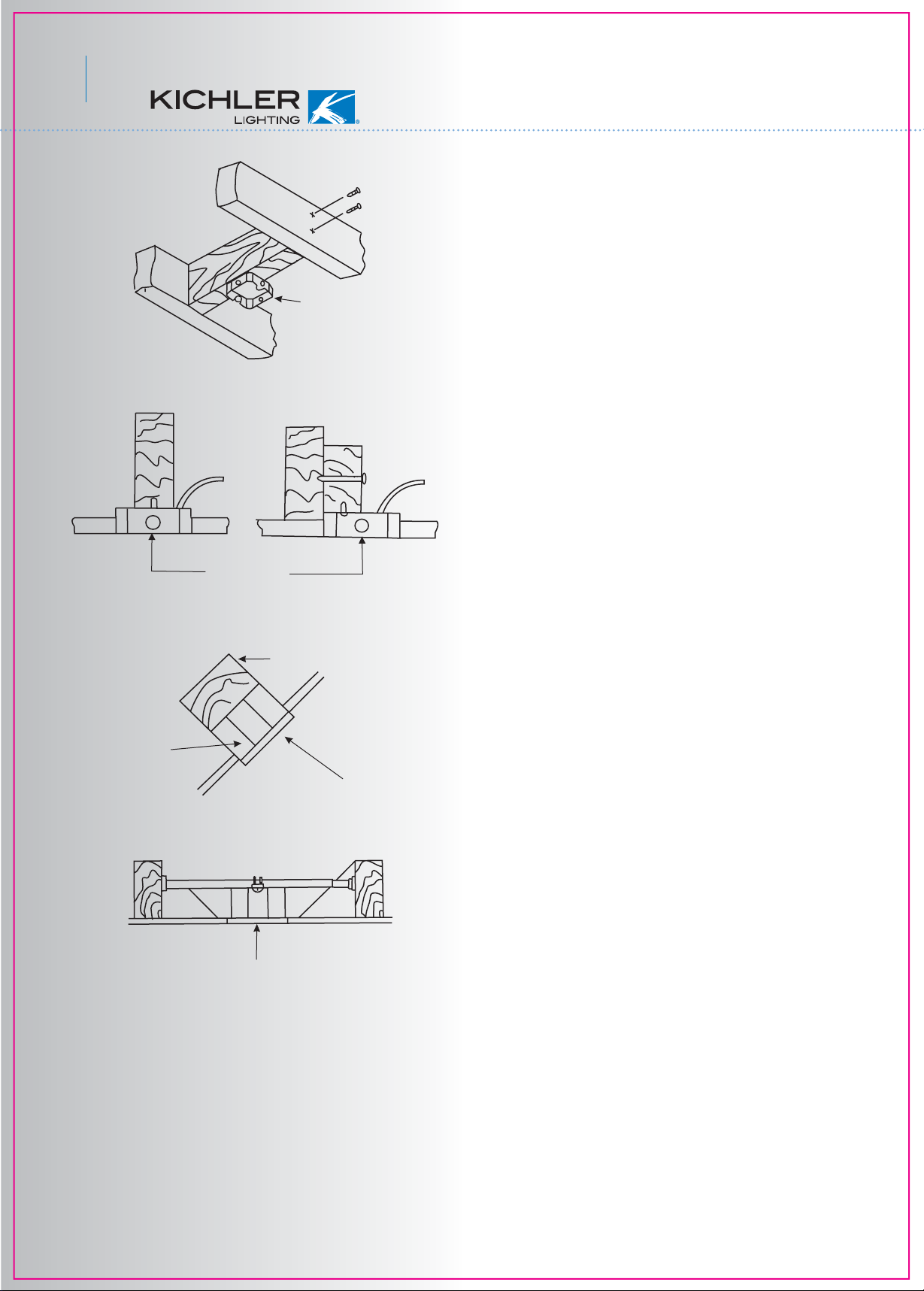
4. MOUNTING OPTIONS
If there isn't an existing UL ( CUL for Canadian
Installation) listed mounting box, then read the
following instructions. Disconnect the power by
removing fuses or turning off circuit breakers.
Fig. 1
Outlet box
Fig. 2
Outlet box
Provide strong
support
Secure the outlet box directly to the building
structure. Use appropriate fasteners and
building materials. The outlet box and its
support must be able to fully support the
moving weight of the fan (at least 50 lbs). Do
not use plastic outlet boxes.
Figures 1,2 and 3 are examples of different
ways to mount the outlet box.
NOTE: You may need a longer downrod to
maintain proper blade clearance when
installing on a steep, sloped ceiling. (Fig. 3)
To hang your fan where there is an existing
fixture but no ceiling joist, you may need a
joist hanging bracket as shown in Fig 4.
Recessed
outlet box
Ceiling
mounting
plate
Fig. 3
Outlet box
Fig. 4
Page 5
5. HANGING THE FAN
REMEMBER to turn off the power. Follow the
steps below to hang your fan properly:
Screw
Meredith
TM
4
Step 1. Remove the fan motor and housing
assembly from the protective plastic bag and
take the lower styrofoam packing pad out of
the carton. Place the styrofoam pad on the
floor, then place the fan assembly into the
styrofoam pad with the bottom of the motor
facing up. (The styrofoam pad serves as a
holder for the fan during the first stages of
assembly). Remove the plastic motor shipping
blocks and discard. (Fig. 5)
Step 2. Secure the mounting bracket to the
ceiling outlet box using screws and washers
provided with the outlet box. (Fig. 6)
Step 3. Use a screwdriver to loosen the
cross pin and remove it from downrod
assembly. Loosen the set screw and rotate
the hanger ball off the downrod. (Fig. 7)
Step 4. Loosen the two set screws and
remove the hitch pin and lock pin from
the motor coupling assembly. (Fig. 8)
Step 5. Carefully feed fan electrical wires up
through the downrod. Thread the downrod
onto the motor coupling until the hitch pin
holes are aligned. Next, replace hitch pin and
lock pin, and tighten both set screws. (Fig. 8)
shipping block
Fan housing
Fig. 5
CUL listed electrial box
Mounting bracket
Washer
Mounting screw
120V wires
Fig. 6
Hanger Ball
Set Screw
Cross Pin
Downrod
Set screw
Lock pin
Fig. 7
Downrod
Hitch pin
Fig. 8
Page 6

5
Step 6. Slip the coupling cover, decorative
arm, canopy cover and canopy onto the
Downrod
Canopy
downrod. Reinstall the hanger ball onto the
downrod and make sure the cross pin is in
place and the set screw on hanger ball is
tight. Secure the decorative arm assemble
(with the lower ends resting on the top of
Canopy cover
Set screw
the ceiling fan) by tightening the set screw.
(Fig. 9)
Decorative arm
Registration slot
Fig. 9
Fig. 10
Coupling cover
Step 7. Now lift the motor assembly into
position and place the hanger ball into the
hanger bracket. Rotate until the “Check Tab”
has dropped into the “Registration Slot” and
seats firmly. (Fig. 10) The entire motor
assembly should not rotate if this is done
correctly.
NOTE: The entire motor assembly should
not rotate if this is done correctly.
NOTE: Please make sure all set screws
are in place and tight before installation
the following steps.
Page 7

Meredith
TM
6
6. INSTALLATION OF SAFETY SUPPORT
( For Canadian Installation ONLY )
A safety support cable is provided to help prevent
the ceiling fan from failing, please install it as
follows.
Step 1. Attach the provided wood screw and
washers to the ceiling joist next to the mounting
bracket but do not tighten. (Fig. 11-1)
Step 2. Adjust the length of the safety cable to
reach the screw and washers by pulling the extra
cable through the cable clamp until the overall
length is correct, put the end of the cable back
through the cable clamp, forming a loop at the
end of the cable. Tighten the cable clamp
securely. Now, put the loop in the end of the
safety cable over the wood screw and under the
washer. Tighten the wood screw securely. See
Fig. 11-2
7. MAKE THE ELECTRIC CONNECTIONS
WARNING: To avoid possible electrical shock,
be sure the electricity is turned off at the main
circuit breaker or fuse box before wiring.
WARNING: If your house wires are different
colors than referenced in this manual, stop
immediately. A professional electrician is recommended to determine proper wiring.
NOTE: The CoolTouch™ Control System is
equipped with 16 code combinations to prevent
possible interference from or to other remote
units. The frequency switches on your receiver
and transmitter have been preset at the factory.
Please recheck to make sure the switches on
the transmitter and receiver are set to the same
position, any combination of setting will operate
the fan as long as each switch on the transmitter
and receiver are set to the same opposition.
(Fig. 12) Changing the order of switches on
each switch block, changes the operational
frequency.
Step 1. Insert the receiver into the mounting
bracket, with the flat toward the ceiling. (Fig. 13)
Step 2. Motor to Receiver Electrical Connections:
NOTE: Make all of the following connections
with “Wire Nut” connectors.
Connect the black wire from the fan to black
wire marded “TO MOTOR L” from the receiver.
Connect the white wire from the fan to the white
wire marked “TO MOTOR N” from the receiver.
Connect the blue wire from the fan to the blue
wire marked “For Bottom Light” from the
receiver. Place a plastic wire nut on the end of
the Orange Wire coming from the receiver
marked “For Upper Light”. Your ceiling fan is not
equipped with a Upper Light. Secure all the wire
connections with the plastic wire nut provided.
(Fig. 14 on the next page)
Code switch
Receiver
Support Brace
Ceiling
Fig. 11-1
Fig. 11-2
Battery Compartment
Fig. 12
Fig. 13
Flat Washer
Wood Screw
Spring Washer
Outlet Box
Safety Cable bolt
Wood Screw
Hanger
bracket
Page 8

7
Outlex box
Black (hot)
Black("AC" IN L")
Receiver
Black ("to motor L")
Blue ( for bottom light
Orange (For upper light)
Step 3. Remote Receiver to Outlet Box Electrical Connections: Connect the black
(hot) wire from the ceiling to the black wire
White (neutral)
Green or bare
Copper (ground)
White("AC IN N")
marked "AC in L" from the receiver. Connect
the white(neutral) wire from the ceiling to the
white wire marked "AC in N" from the
Receiver. Secure the wire connections with
the plastic wire nuts provided. (Fig. 14)
Step 4. If your outlet box has a ground wire
)
White("to motor N")
Ground wire
(green or bare copper) connect it to the fan
ground wires. Secure the wire connection with
a plastic nut provided.
Blue(motor)
Black (motor)
Outlet box
Hanger bracket
Fig. 14
White (neutral)
Screw
NOTE: Carefully tuck the wire connections up
into the outlet box. (Fig. 14)
NOTE: The transmitting unit must be installed
at a maximum distance of 30 feet from the
ceiling fan for proper signal transmission
between the transmitting unit and the fan’s
receiving unit.
8. INSTALLING THE CEILING CANOPY
WARNING: One last time, make sure the “Check
Tab” at the bottom of the hanger bracket is properly seated in the “Registration Slot” on the side
of the hanger ball before attaching the canopy to
the bracket. Failure to properly seat the “Check
Tab” could damage the electrical wires when the
ceiling fan blade direction is changed while the
fan is running.
Fig. 15
Canopy
Canopy cover
Step 1. Make sure all of the electrical connections are tucked neatly into ceiling outlet box.
Step 2. Slide the canopy up to ceiling fan and
onto the two screws on hanger bracket. Rotate
the canopy clockwise and tighten the two screws.
Next, while holding the canopy with one hand,
slide the canopy cover over the screws and
rotate clockwise until tight.
NOTE: You may need to adjust the canopy
mounting screws as necessary until the canopy
and canopy cover have a snug fit. (Fig. 15)
Page 9

9. ATTACHING THE FAN BLADES
Meredith
TM
8
Step 1 Attach the blade to the blade bracket
using the screws, washers and fiber washers
as shown in Figure 16. Start screw into
bracket. Repeat for the two remaining screws.
Step 2. Make sure the blade is straight and
tighten each screw until the fiber washer is
slightly compressed and all three screws are
secure.
Step 3. Fasten blade assembly to motor using
"pre-installed" mounting screws in the blade
bracket . (Fig. 17)
Screw
Metal washer
Silicon washer
Blade
Blade bracket
Fig. 16
Screw
Blade bracket
Fig. 17
10. INSTALLATING THE MOUNTING PLATE
Step 1. Remove 1 of the 3 screws on the
mounting ring and loosen the other 2 screws.
Do not remove the mounting ring located on
the motor shaft.
Step 2. Place the key holes on the mounting
place over the remaining 2 screws on the
mounting ring, turn mounting plate until it locks
in place at the narrow section of the key holes.
Secure by tightening 2 screws and reinstalling
the third screw. (Fig. 17)
NOTE: If you would like to install the light
fixture that come with your ceiling fan, please
skip to step 12 and continue. If you want your
ceiling fan installed without the light fixture,
follow step 11 and then skip to Step 14.
Mounting plate
Connection plug
Fig. 18
Page 10

9
11. INSTALLING THE SWITCH HOUSING
NOTE: Before continuing, make sure the power
is disconnected by turning off the circuit breaker
or removing the fuse at the circuit box.
Mounting plate
Connection plug
Switch housing
Fig. 19
Step 1. Loosen the 3 screws on the switch
house mounting plate.
Step 2. The square plastic wiring connector
from the ceiling fan and the light fixture will only
fit together one way. Match up the color on the
side of the connector, then push them together
until the snap engages.
Step 3. Tuck the connections neatly into the
switch housing. Align the key holes on the
switch housing with the screws on the mounting
plate. Turn the switch housing until it locks in
place at the narrow end of the key holes.
Tighten all 3 screws previously loosened.
(Fig. 19)
Switch housing
Plastic nut
Isolation plate
White wire
Black wire
Capacitor
Fig. 20
B
90
1
Z
H
V 60
No: PLl
20
/RED
E
1
de
IT
IN L
AC
Mo
WH
/
AC
N
K
C
N
I
A
L
T/B
AC
GH
I
L
t
mi
i
)
L
r
e
OFF
ast
N/
l
Pow
O
(
Bal
W
or
0
t
n
.19
e
x
c
s
Ma
de
an
c
n
I
Nut
Lock washer
Metal washer
Limiter
Reverse
module
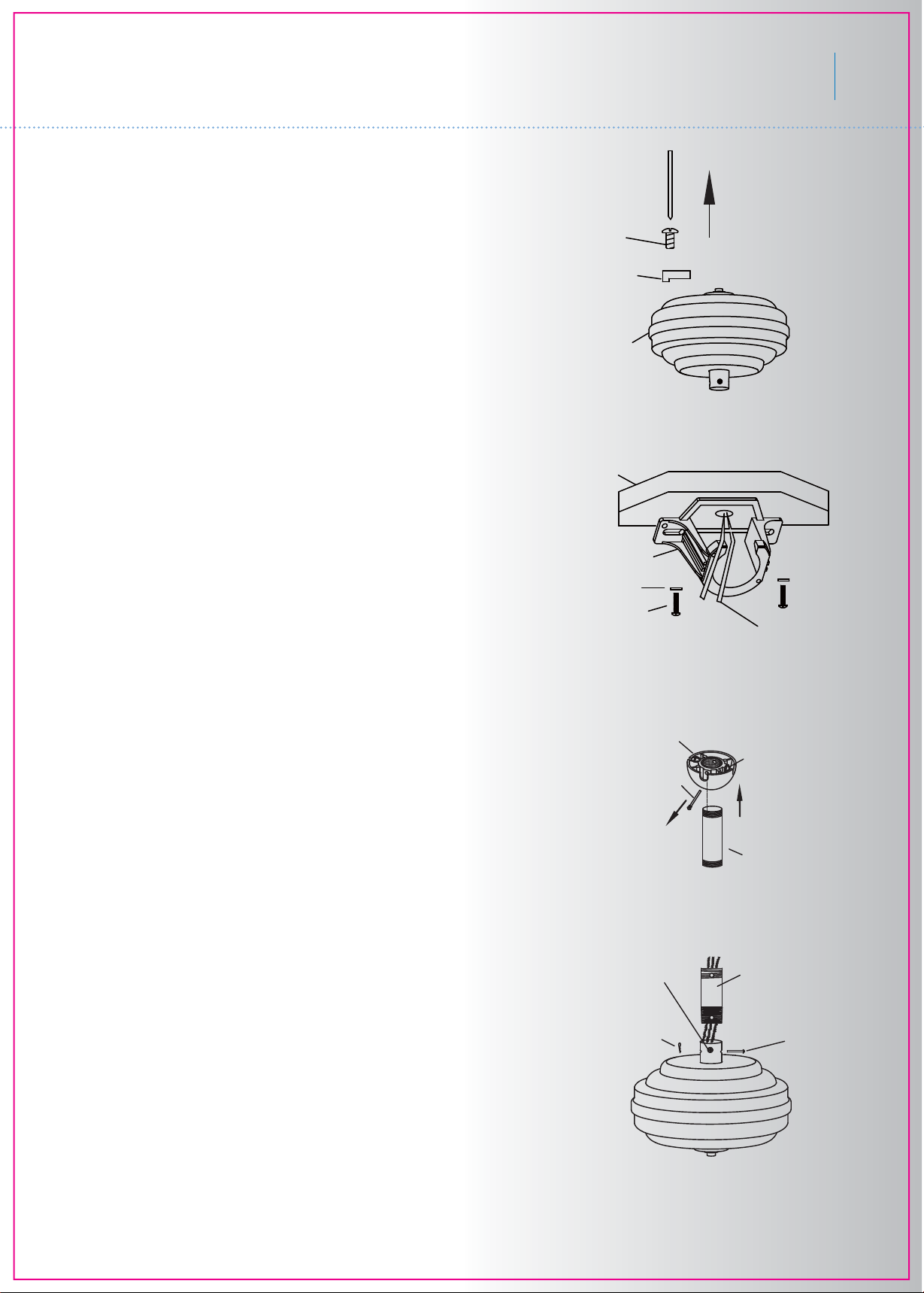
12. INSTALLING THE LIGHT KIT
Step 1. Remove the finial NUT located in the
center of the switch housing. See Fig. 20.
Step 2. Remove the lock washer, metal washer
and hex nut from the light fixture mounting
stem.
Step 3. Feed the electrical wires from the light
fixture through the hole in the switch housing
(starting with the black wire first, it has a larger
connector). Thread the light kit onto the
switch housing, add the metal washer, lock
washer and hex nut on the inside of the switch
housing and tighten securely.
NOTE: Please take the reverse module, capacitor and 190w power limiter out of the switch
housing prior to threading the light kit to switch
housing.
Page 11

Step 4. Connect the black wire connectors
from the light fixture and switch housing by
pushing them together. Follow the same
procedure with the white wire connectors.
Meredith
TM
10
Step 5. The square plastic wiring connector
from the ceiling fan and the light fixture will
only fit together one way. Match up the
color on the side of the connector, then
push them together until the snap engages.
Step 6. Tuck the connections neatly into
the switch housing. Align the key hole on
the switch housing with the screws on the
mounting plate. Turn the light fixture until it
locks in place at the narrow end of the key
holes. Tighten all 3 screws previously
loosened. (Fig. 21)
13. INSTALLING THE LIGHT BULB
& GLASS SHAED
Connection plug
Light kit
Fig. 21
Glass shade
Silicon washer
Manual nut
Metal washer
Decoration plate
Finial
Fig. 22
Page 12

11
Fig. 23
14. OPERATING INSTRUCTIONS
Restore power to ceiling fan and test for
proper operation.
A. , , and buttons:
These three buttons are used to set the
fan speed as follows:
= low speed
= medium speed
= high speed
B. button:
This button turns the fan off.
C. The " " button:
Press to turn the upper light on and off,
hold for full range dimming. (If your ceiling fan
is equipped with an “Upper Light”)
Fig. 24
D. The " " button:
Press and release the button to turn the
light ON or OFF. Press and hold the button to
set the desired brightness. The light key has
an auto-resume, it will stay at the same
brightness as the last time it was turned off.
D. The " " button is used to set the fan
forward or reverse. Press the button for forward
(for warm weather) or reverse (for cool
weather).
Speed settings for warm or cool weather
depend on factors such as the room size.
Ceiling height, number of fans and so on.
NOTE: To operate the reverse function on this
fan, press the reverse button while the fan is
running.
Warm weather-(Forward) A downward airflow
creates a cooling effect as shown in Fig. 24..
This allows you to set your air conditioner on
a warmer setting without affecting your comfort.
Fig. 25
Cool weather - (Reverse) An upward airflow
moves warm air off the ceiling area as shown
in Fig. 25. This allows you to set your heating
unit on a cooler setting without affecting your
comfort.
Page 13

Page 14

 Loading...