

Page 1
SAFETY INSTRUCTIONS
READ THIS FIRST
KEEP THESE INSTRUCTIONS
This xture is intended for installation in accordance with the National
Electric Code (NEC) and Local code specications. Failure to adhere to
these codes and instructions may result in serious injury and/or property
damage and will void the warranty.
1) WARNING: This xture is not to be installed within 10 feet (3M) of a pool,
spa or fountain.
2) This xture is to be used only with a power unit (transformer) rated a
maximum of 300 W (25 AMPS) 15 volts.
3) The #18 ga. xture wire is not intended for direct burial.
4) Direct burial rated wire is to be buried a minimum of 6” (152mm) beneath
the surface of the ground.
NOTE: If additional Direct Burial wire is needed, contact your local Kichler®
landscape distributor.
• 8 GA wire can be purchased in length of 250’ (76 M), 15503-BK.
• 10 GA wire can be purchased in length of 250’ (76 M), 15504-BK.
• 12 GA wire can be purchased in lengths of 100’ (30 M), 15501-BK; 250’
(76 M), 15502-BK; 500’ (152M), 15505-BK; and 1000’ (304 M), 15506-BK.
5) Fixture shall not use a tungsten halogen lamp unless the xture is marked
for use with such lamps.
6) Wiring connections must be made with approved/listed wire connection
device(s) suitable for the application. Do not exceed manufacturers’ wiring
combination specications for size and quantity of conductors.
INSTRUCTIONS PERTAINING TO A RISK OF FIRE, OR INJURY TO
PERSONS
IMPORTANT SAFETY INSTRUCTIONS
Lighted lamp is HOT!
WARNING — To reduce the risk of FIRE OR INJURY TO PERSONS.
1) Turn off / unplug and allow to cool before replacing lamp.
2) Lamp gets HOT quickly! Contact only switch / plug when turning on.
3) Do not touch hot lens or cowl.
4) Do not remain in light if skin feels warm. (Light is intense, it may cause
“sunburn”.)
5) Do not look directly at lighted lamp.
6) Keep lamp away from materials that may burn.
7) Use only with wattage and lamp marked on xture.
8) Do not touch the inner glass envelope of the lamp at any time. Use a soft
cloth. Oil from skin may damage lamp.
9) Do not operate the xture with a damaged or missing lens.
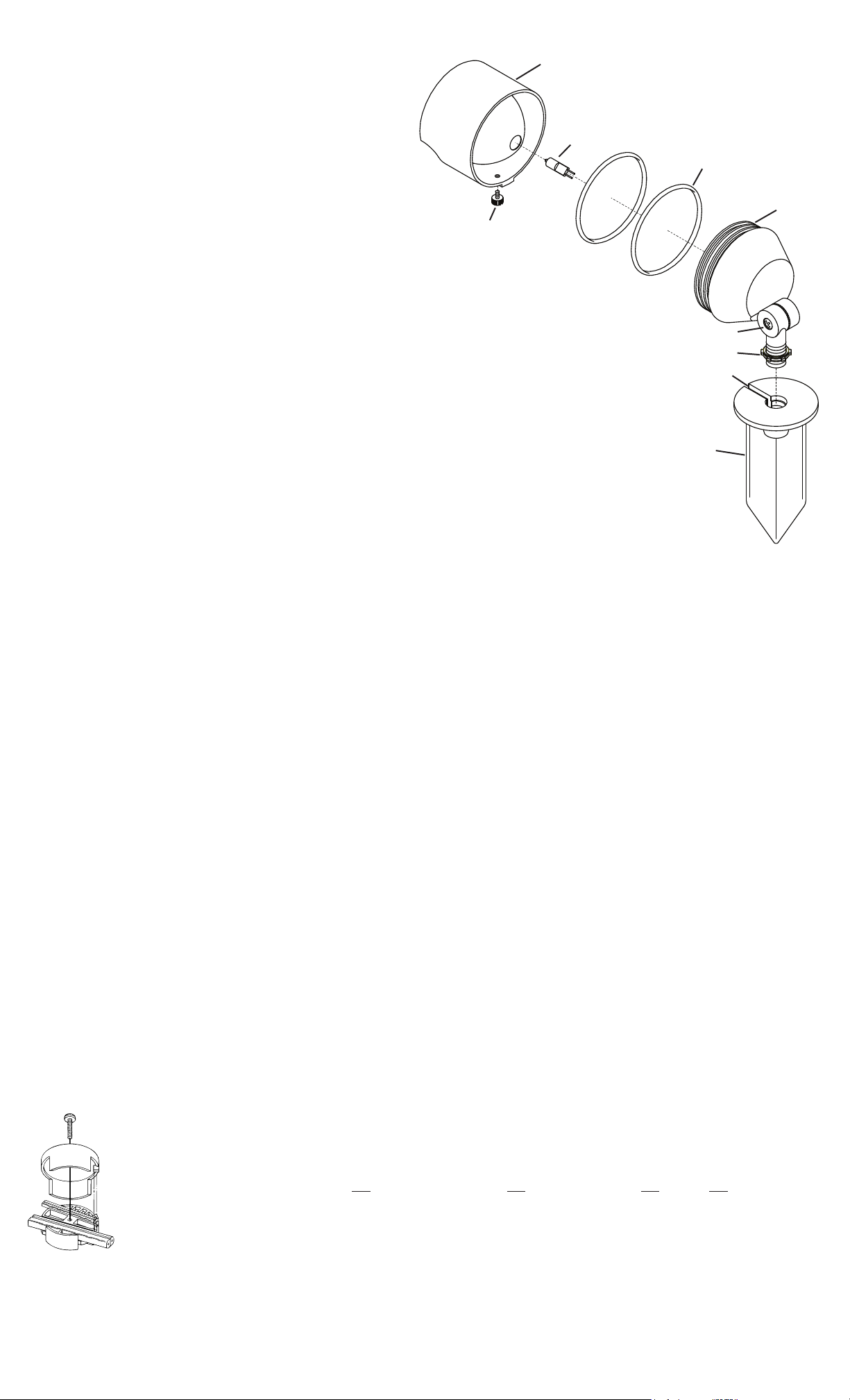
E
J
C
D
F
H
G
B
A
WHEN INSTALLING KICHLER LANDSCAPE LIGHTING (LINE VOLTAGE OR LOW VOLTAGE),
CARE SHOULD BE TAKEN TO KEEP CLEAR OF POTENTIALLY COMBUSTIBLE MATERIALS.
WHEN MAINTAINING THE FIXTURES, BE SURE TO REMOVE LEAVES, PINE NEEDLES,
GRASS CLIPPINGS, MULCH, OR ANY DEBRIS THAT HAS ACCUMULATED ON THE LIGHT
BULB, LENS, OR BODY OF THE FIXTURE.
ASSEMBLY AND INSTALLATION
1) Determine desired location for mounting xture.
2) At desired location, hammer stake (A) into ground. To avoid damage to
stake, place a board on top of stake while hammering. If ground is hard
and stake is difcult to install, make a crosscut in ground using a at
shovel.
3) Clear away area in ground at wireway slot (B) in top of stake (A).
4) Slip O-ring (C) over accent light body and into groove (D) closest to center
of accent light.
5) Slip second O-ring into groove farthest from center of accent light.
6) Install lamp (J) (not supplied) to socket inside accent light. NOTE: Use
caution when installing. Hold lamp by outer housing. DO NOT touch glass
envelope inside. If this happens, clean lamp with denatured alcohol and a
lint free cloth.
7) Assemble cowl (E) to accent light. Secure in place using either the
provided thumbscrew (F) or the vandal resistant screw. NOTE: Vandal
resistant screw requires a 3/32 hex key (not provided) for installation or
removal.
8) Lay 12V cable into wireway slot (B) and screw xture into stake (A). When
at desired direction run locknut (G) down against stake (A).
9) Adjust angle of accent light by loosening screw (H).
10) TURN OFF POWER.
11) Make wire connections using supplied Quic Disc™ following instructions
below, or using other approved wiring connection method (not supplied.)
CAUTION
Turn off power.
The full length of the 18 GA xture wire may be used to connect with the 10 GA or 12 GA cable provided the following conditions are met:
• Wiring is to be protected by routing close to the xture or accessory or secured to a building structure such as house or deck.
• 18 GA xture wiring is to be cut off so that it is attached to the connector within 6 inches of the xture or building structure.
• If it is necessary to make the connections underground, then no more than 6 inches of the 18 GA xture wire is to be buried.
The Quic Disc™ connector is designed to install one xture and accommodates one 18 GA xture wire and one 10 GA or one 12 GA supply wire.
Place the 10 gauge supply wire across the area marked 10 GA on Quic Disc™ or place the 12 gauge supply wire across the area marked 12 GA
on Quic Disc™.
Place the 18 gauge xture wire across the area marked 18 GA on the Quic Disc™. After the wires are in place, connecta the top of the Quic
Disc™ to the base with supplied screw, making sure that the wires remain at in the bottom portion of the Quic Disc™, and the screw is tightened
all the way down.
The copper contacts will automatically pierce the wires’ insulation. Excess 18 GA xture wire that sticks out the end of the Quic Disc™ is to be cut off.
Make no other wiring connections to the 18 GA xture wire.
Quic Disc™ WIRING INSTRUCTIONS
For warranty information please visit: http://www.landscapelighting.com/portal/warranty_page
Para informacion de la garantia por favor visite: www.landscapelighting.com/portal/warranty_page
Date Issued: 1/27/12 IS-15383-US
Page 2
INSTRUCCIONES DE SEGURIDAD
PRIMERO LEA ESTO
GUARDE ESTAS INSTRUCCIONES
Este artefacto se debe instalar de acuerdo con el Código Eléctrico
Nacional (NEC, por sus siglas en inglés) y con las especicaciones del
código local. No cumplir con estos códigos e instrucciones puede
resultar en lesiones graves y/ o en daños a la propiedad y anulará la
garantía.
1) Advertenciaertencia: Este artefacto no debe instalarse a menos de
10 pies (3 m) de una piscina (alberca), spa o fuente.
2) Este artefacto debe utilizarse solamente con una unidad de potencia
(tranformador) con capacidad nominal máxima de 300 vatios (25 amp.)
15 voltios.
3) El alambre del artefacto calibre No. 18 no es para soterrado directo.
4) El alambre clasicado para soterrado directo se debe enterrar un mínimo
de 6 pulgadas (152 mm) debajo de la supercie del terreno.
NOTA: Si necesita alambre de soterrado directo adicional, comuníquese
con su distribuidor local Kichler® de productos de jardinería ornamental.
• El alambre calibre 8 puede comprarse en longitud de 250’ (76 m.),
15503-BK
• El alambre calibre 10 puede comprarse en longitud de 250’ (76 m.),
15504-BK
• El alambre calibre 12 puede comprarse en longitudes de 75’ (22 m.),
15550-BK; 100’ (30 m.), 15501-BK; 250’ (76 m.), 15502-BK; 500’ (152 m.),
15505-BK; y 1000’ (304 m.), 15506-BK.
5) El artefacto no debe utilizarse con lámparas de halógeno, a menoss que
el artefacto esté marcado para usar con tales lámparas.
6) Las conexiones de cableado se deben hacer con las conexiones del(los)
dispositivos) de conexión de cableado aprobados/ de la lista, adecuados
para la aplicación. No exceda las especicaciones de combinación de
cableado del fabricante para el tamaño y cantidad de conductores.
INSTRUCCIONES PERTINENTES A UN RIESGO DE ICENDIO O
LESION A LAS PERSONAS
INSTRUCCIONES IMPORTANTES DE SEGURIDAD
¡La lámpara encendida es CALIENTE!
ADVERTENCIA — Para disminuir el riesgo de INCENDIO O LESION A LAS PERSONAS.
1) Apague / desenchufe y deje que se enfríe antes de cambiar la lámpara.
2) ¡La lámpara se CALIENTA rápidamente! Haga contacto del conmutador/
enchufe sólo cuando encienda.
3) No toque la lente o la capucha caliente.
4) No permanezca en la luz si siente tibia la piel. (La luz es intensa, puede
causar “quemaduras de sol”).
5) No mire directamente a la lámpara encendida.
6) Mantenga la lámpara alejada de los materiales que puedan encenderse.
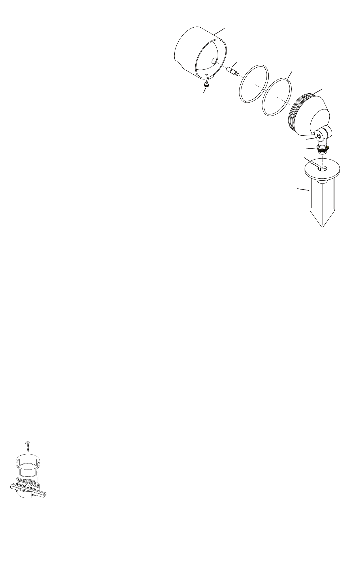
E
J
C
D
F
H
G
B
A
CUANDO SE INSTALE SISTEMAS DE ALUMBRADO KICHLER PARA JARDINES (YA SEA DE
VOLTAJE DE LINEA O CON VOLTAJE BAJO) SE DEBE TENER CUIDADO DE MAINTNERLOS
ALEJADOS DE MATERIALES QUE PUEDAN SER COMBUSTIBLES EN POTENCIA.
AL DAR SERVICIO DE MANTENIMIENTO A ESTOS SISTEMAS, ASEGURESE DE DESPEJAR
LAS HOJAS, CONOS DE PINO, RECORTES DEL PASTO, CUBIERTA DE PAJA O CUALQUIER
BASURA QUE SE HAYA ACUMULADO EN LA BOMBILLA DE LUZ, EL LENTE O EL SOPORTE
DE LA BOMBILLA.
MONTAJE E INSTALACIÓN
1) Determine el lugar deseado donde montar el artefacto.
2) En el lugar deseado, martille la estaca (A) en el suelo. Para evitar dañar la
estaca, coloque una tabla en la parte superior de la estaca mientras esté
martillando. Si el suelo es duro y es difícil instalar la estaca, haga un corte
en cruz en el suelo usando una pala plana
3) Limpie el área del suelo en la ranura (B) del canal de alambres en la parte
superior de la estaca (A).
4) Deslice el anillo en O (C) sobre el cuerpo de la luz de acento y en la
muesca (D) más cercana al centro de la luz de acento.
5) Deslice el segundo anillo en O en la muesca más lejana del centro de la
luz de acento.
6) Instale la bombilla (J) (no se provee) al casquillo dentro de la luz de
acento. NOTA: Tenga cuidado al instalar. Sostenga la bombilla de la
cubierta protectora. NO toque la envolvente de vidrio de adentro. Si esto
sucede, limpie la bombilla con alcohol desnaturalizado y una tela sin
pelusas.
Apague la alimentación de energía.
El largo total del alambre calibre 18 del artefacto se puede utilizar para conectar con un cable calibre 10 ó 12, con tal que se cumplan las condiciones siguientes:
• El alambrado se debe proteger encaminando cerca al artefacto o accesorio o asegurado a la estructura de un edicio, tal como una casa o
cubierta.
• El alambrado calibre 18 del artefacto debe cortarse de manera que se una al conector dentro de las 6 pulgadas del artefacto o de la estructura
del edicio.
• Si fuere necesario hacer las conexiones bajo tierra, como máximo 6 pulgadas del alambre calibre 18 del artefacto se debe enterrar.
El conector Quic Disc™ está diseñado para instalar un artefacto y acomodar un alambre de artefacto de calibre 18 y otro de calibre 10, o bien un
alambre de alimentación de calibre 12.
Coloque el alambre de alimentación calibre 10 a través del área marcada calibre 10 en el Quic Disc™ o ponga el alambre de alimentación calibre
12 a través del área marcada calibre 12 en el Quic Disc™.
Ponga el alambre calibre 18 del artefacto a través del área marcada calibre 18 en el Quic Disc™.
Después que los alambres estén en su lugar, conecte el tope del Quic Disc™ a la base con el tornillo que se provee, asegurándose de que los alambres
permanezcan en la porción inferior del Quic Disc™, y el tornillo esté todo apretado hacia abajo.
Los contactos automáticamente perforarán la aislación de los alambres. El exceso de alambre calibre 18 del artefacto que sobresale del extremo Quic Disc™ debe
cortarse.
No haga otras conexiones de cableado al alambre del artefacto de calibre 18.
PRECAUCION
7) Monte la capucha (E) en la luz de acento. Asegure en su lugar usando el
tornillo de mariposa (F) que se provee o el tornillo resistente a manipulaciones.
NOTA: El tornillo resistente a manipulaciones requiere una llave hexagonal
de 3/32 (no se provee) para la instalación o retiro.
8) Coloque un cable de 12 V en la ranura (B) del canal de alambres y atornille el
artefacto en la estaca (A). Cuando esté en la dirección deseada, corra
hacia abajo la tuerca de seguridad (G) contra la estaca (A).
9) Ajuste el ángulo de la luz de acento aojando el tornillo (H).
10) APAGUE LA ALIMENTACIÓN ELÉCTRICA.
11) Haga las conexiones de cableado usando el Quic Disc™ suministrado y
siguiendo las instrucciones de abajo, o usando otro método de conexión
de cableado aprobado (no se suministra.)
INSTRUCCIONES DE ALAMBRADO DE QUIC DISC
™
For warranty information please visit: http://www.landscapelighting.com/portal/warranty_page
Para informacion de la garantia por favor visite: www.landscapelighting.com/portal/warranty_page
Date Issued: 1/27/12 IS-15383-US
 Loading...