

KIA Genuine Accessories
Vehicle Model Sorento (Push Button) Accessory Remote Engine Start
Model Year 2011~ Diffi culty ( B )
KMA Part No. U8560 1U010
Note: Diffi culty stated above refl ects the minimum level of expertise required to install the accessory
( A ) Customer ( B ) Dealer Technician ( C ) Master Technician
Ensure vehicle is equipped with automatic transmission, power door locks
and power windows. If the vehicle is not equipped with these options, do
Instruction Symbols / Defi nitions
not proceed. Ensure vehicle DOES have SMART KEY.
Denotes warnings that may lead to
serious physical injury or vehicle
!
damage.
Denotes cautions to be taken to avoid
physical injury or electronic component
damage.
Denotes cautions to be taken to avoid
vehicle and component damage.
Basic Required Hand Tools
1/4” Drive 10 mm
1/4” Drive Rachet
Phillips
Screwdriver
Socket
Pliers
N
O
T
E
1/4” Drive 3/8”
Deep Socket
1/4” Drive 6”
Extension
Denotes quality processes to be
checked prior to moving to the
next step.
Denotes specifi c tools that are neces-
sary to complete the step.
Denotes safety equipment required to be used
such as a mask, goggles, rubber
gloves, and hearing protection.
Mask
Denotes instructional steps
necessary to complete the
process.
Rubber Gloves Hearing Protection
Notes to the Installer:
Read the entire installation manual prior to beginning the
installation of the accessory.
Factory wire harness colors are subject to change, please use
the specifi ed pin # in the harness connector to identify the cor-
rect wire for T-Tap installation.
Ensure that the vehicle is properly protected in the area that
the accessory is to be installed.
To prevent vehicle damage, never place tools on top of painted
surfaces, seats, dash pad, console or fl oor carpet / mat.
Always wear appropriate safety gear to include gloves and eye
protection when required.
Prior to disconnecting the negative lead to the battery, note the
AM/FM and satellite set frequencies on the inspection page, if
applicable.
Googles
Trim Tool Wire Cutter
Alcohol Cleaner
Center Fascia
Removal Tool
P/N: 09840-1E100
1/4” Drive Torque
Wrench
For Authorized Dealers - (800) 667-5176
Hours: 9:00 a.m. - 6:00 p.m. EST Monday - Friday
9:00 a.m. - 3:00 p.m. EST Saturday
Flat Screwdriver
To prevent stress on the remote start wire harness, ensure the
tilt/telescopic steering column is fully extended, if equipped.
Ensure the transportation fuse is properly installed before
performing the function check on page 17.
Technical Support
Revision Date
3/9/2012
P/N: 4280402, Rev. A
Page 1 of 27
KIA Genuine Accessories
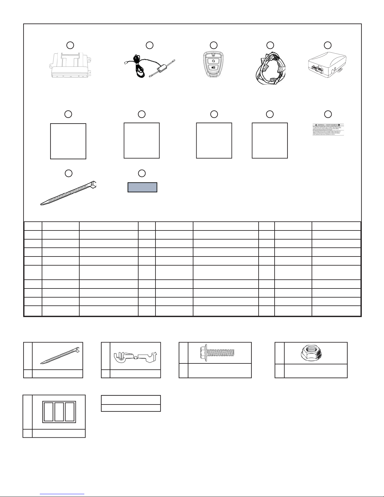
1 2 3 4 5
Control Module P/N: U8560 00002
P/N: 00056 ADU50 P/N: U8560 00009
DNA P/N: U8560 00014
6
Hardware
Kit
7
Installation
Instructions Warning Label
8
Owner’s
Guide
P/N: XMIN-U8560 1U010-DP
11
12
Foam Tape
15” Wire Tie (Large)
No. Qty. Descriptioin No. Qty. Description
1 1 Control Module/DNA 10 1 Warning Label
2 1 Dipole Antenna 11 6 15” Wire Tie (Large)
3 2 Transmitters 12 1 Foam Tape
4 1 Wire Harness
5 1 Immobilizer Interface
6 1 Hardware Kit
7 1 Installation Instructions
8 1 Owner’s Guide
9 1 Quick reference Guide
Module
P/N: U8561 1U010
9
Quick
Reference
Guide
P/N: U8560 00010
10
A
8” Wire Tie (Small)15
E
B
Female T-Tap6
Hardware Kit Total
26
3
Foam Tape
C
#10-24 Serrated Flange
1
Hex Bolt
Revision Date
3/9/2012
D
#10-24 Serrated Flange
1
Hex Nut
Page 2 of 27
KIA Genuine Accessories (General Procedures)
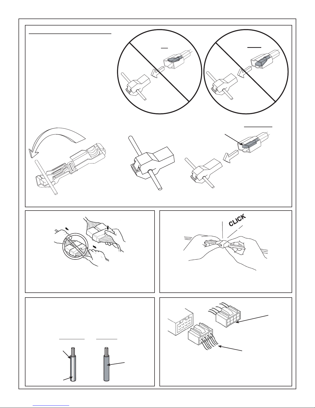
T-Tap Installation Procedure
Factory wire harness colors are subject
to change, please use the specifi ed pin
# in the harness connector to identify
the correct wire for T-Tap installation.
Spade Terminal
Pointed Up
Spade Terminal
Pointed Down
INCORRECT INCORRECT
1. Place T-Tap on vehicle wire.
N
O GOO
NO GOOD
D
2. Using pliers, close and crimp
T-Tap around vehicle wire.
** Extreme care must be taken to ensure that the male spade
terminal is inserted into the T-Tap properly.
CORRECT
Spade Terminal CENTERED
Inside Connector
3. Insert harness wire with
male spade terminal
end into the T-Tap.
Disconnecting Connectors
When disconnecting connectors, grasp the connectors, not the wires.
Wire Colors
When a two-color wire is listed, the fi rst color indicates
the base color of the wire, the second color indicates
the color of the stripe. For example: Black/White.
Striped Wire
Black
(Base Color)
White
(Stripe Color)
Solid Wire
Black
Locking Connectors
When locking connectors, listen for a click indicating
they are securely locked.
Terminal End View
Harness End View
Connector Diagrams
Connector diagrams may be shown on the harness side or the terminal side, extreme care must
be taken to verify proper terminal location before a
T-Tap connection is made.
Revision Date
3/9/2012
Page 3 of 27
KIA Genuine Accessories (Vehicle Disassembly)
Vehicle Preparation
*Clean hands.
*Set the parking brake and open driver’s door window.
*Record radio station presets, if applicable.
*Vehicle should be at room temperature.
*Ensure vehicle is equipped with automatic transmission, power door locks and power windows. If the vehicle
is not equipped with these options, do not proceed. Ensure vehicle DOES have SMART KEY.
*ENSURE THE TILT/TELESCOPIC STEERING WHEEL COLUMN IS FULLY EXTENDED AND LOCKED BEFORE
INSTALLING THIS ACCESSORY.
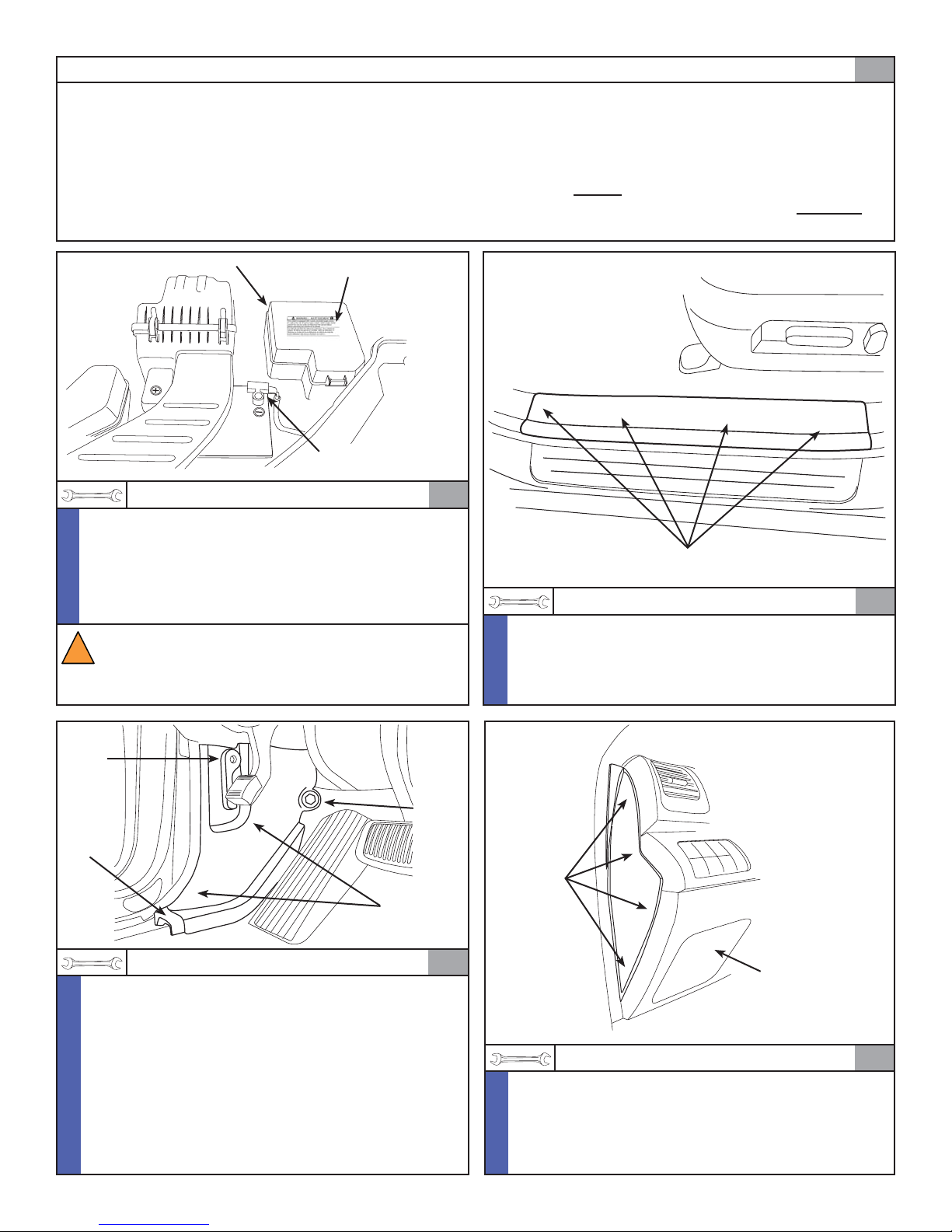
0
Fuse Box
1/4” Drive Rachet, 10 mm Socket
*Remove and isolate the negative battery cable from
N
the battery.
O
*Using alcohol, clean the top surface of the underhood
T
fuse box. Ensure the surface is completely dry.
E
*Remove the backing on the under hood label and
mount in place, as shown above.
WARNING! Shock Hazard. Do not touch
vehicle’s negative battery terminal to vehicle’s
!
positive battery terminal. Serious physical
injury or vehicle damage may occur.
Warning Label
Negative Battery
Cable
1
Pressure Clips
Trim Tool
*Remove the driver’s side front door step sill trim panel
N
by inserting the trim removal tool under the trim panel
O
and prying upward to release the (4) pressure clips.
T
*Disconnect any connectors, if equipped.
E
2
Hood
Release
Lever
Push
Clip
Trim Tool
N
*Carefully pull the weatherstrip away from the side of
O
the driver’s kick panel.
T
*Remove the hood release lever by pulling toward the
E
center of the vehicle.
*Remove the plastic nut located near the vehicle dash-
wall, if equipped.
*Remove the driver’s side kick panel from the vehicle
by pulling upward to release the push clip and prying
toward the center of the vehicle to disengage the (2)
pressure clips.
Plastic
Nut
Pressure
Clips
Revision Date
3
3/9/2012
Pressure
Clips
Fuse Panel
Access Cover
Trim Tool
*Disassembly Tip - Remove the fuse panel access
N
cover to assist in the removal of the driver’s side
O
dash end cap.
T
*Remove the driver’s side dash end cap panel by pry-
E
ing outward to disengage the (4) pressure clips.
Page 4 of 27
4
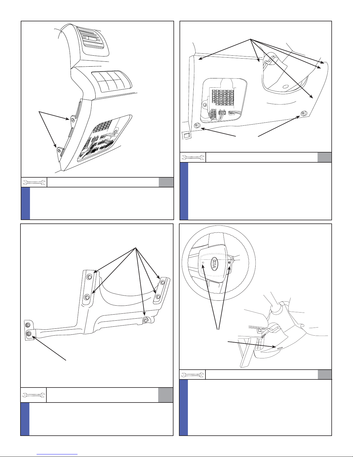
Phillips
Screws
KIA Genuine Accessories (Vehicle Disassembly)
Pressure
Clips
Phillips
Screws
Phillips Screwdriver
*Remove the (2) phillips screws from the side of the
N
lower dash fi nish panel.
O
T
E
10 mm
Bolts
Phillips Screwdriver, T rim Tool
*Remove the lower dash fi nish panel by removing
N
the (2) phillips screws from the bottom of the panel.
O
Using a trim removal tool, carefully pry outward to
5
T
release the (5) pressure clips.
E
*Remove the OBDII connector from the panel.
*Disconnect the remaining connectors, if equipped.
6
10 mm
Nut
1/4” Drive Rachet, 1/4” Drive 6” Extension,
10 mm Socket
*Remove the (5) 10 mm bolts and the (1) 10 mm nut
N
securing the steel knee bolster panel.
O
*Remove the steel knee bolster panel from the vehicle.
T
E
N
7
Revision Date
O
T
E
3/9/2012
Phillips
Screws
Phillips Screwdriver, T rim Tool
*Remove the (3) phillips screws securing the steer-
ing column shroud (1 underneath and 2 behind the
steering wheel). Turn the steering wheel for access.
*Release the tilt steering wheel adjuster lever.
*Pull down to separate (Use trim tool, if necessary)
and remove the lower steering column shroud from
the vehicle.
*Disconnect any connectors, if equipped.
Page 5 of 27
8
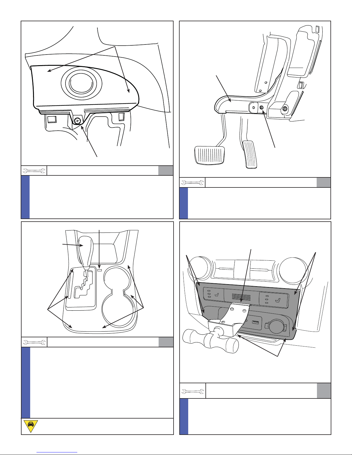
ENGINE
START
STOP
KIA Genuine Accessories (Vehicle Disassembly)
Pressure
Clips
Heater
Air Duct
Phillips
Screws
Phillips Screwdriver, T rim Tool
*Remove the Engine Start/Stop Button switch from the
N
dash assembly by removing (1) phillips screw.
O
*Using a trim removal tool, carefully pry outward to
T
release the (2) pressure clips.
E
*Disconnect the connector attached to the Engine
Start/Stop Button switch.
Gear Selector Access Tab
Gear Selector
Handle
Pressure
Clips
Pressure
Clips
Phillips
Screws
9
Phillips Screwdriver
N
*Remove the (1) phillips screw securing the lower
O
heater air duct to the dashboard assembly.
T
*Remove the lower heater air duct from the vehicle.
E
Insert Center Fascia
Push
Removal Tool Here
Clips
AUX
USB
10
Push
Clips
Flat Screwdriver, T rim Tool
N
*Remove the gear selector access tab.
O
*Push straight down with a fl at screwdriver and shift the
T
gear selector into the drive position.
E
*Remove the gear selector handle by pulling it straight
up toward the headliner.
*Remove the center console/cup holder trim panel by
pulling upward at the cup holder area to disengage
the (6) pressure clips.
*Disconnect the connector and remove the trim panel
from the vehicle.
CAUTION! Ensure parking brake is set.
11
Center Fascia Removal Tool
N
O
T
E
Revision Date
3/9/2012
Pressure Clips
(Located In Corners)
Center Fascia Removal Tool
P/N: 09840-1E100
*Disengage the (2) pressure clips and (4) push clips
securing the heated seat switch panel to the dashboard assembly.
*Disconnect the connectors from the heated seat
switch panel and remove from the vehicle.
Page 6 of 27
12
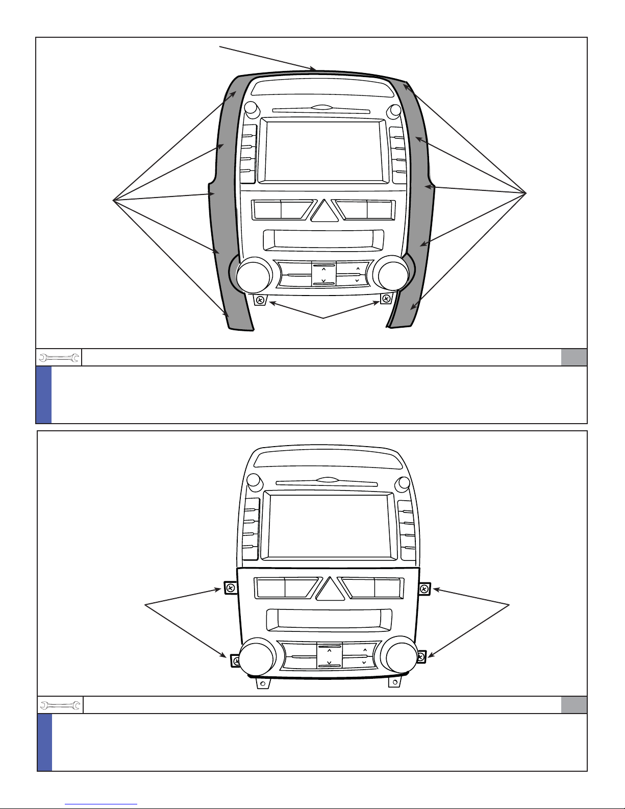
Pressure
Clips
KIA Genuine Accessories (Vehicle Disassembly)
Pressure
Clip
Pressure
Clips
A/C
OFF
MODE
MODE
Phillips
Screws
Phillips Screwdriver, T rim Tool
N
*Remove the (2) phillips screws securing the center fascia trim panel.
O
*Using a trim removal tool, carefully pry outward to release the (11) pressure clips.
T
*Disconnect the passenger airbag connector and remove the trim panel from the vehicle.
E
13
Phillips Screws
Phillips Screwdriver
*Remove the (4) phillips screws securing the heater control unit.
N
*Disconnect the connectors and remove the heater control unit.
O
*Return the Gear Selector lever to the Park position.
T
E
A/C
OFF
Revision Date
3/9/2012
Phillips Screws
MODE
MODE
14
Page 7 of 27
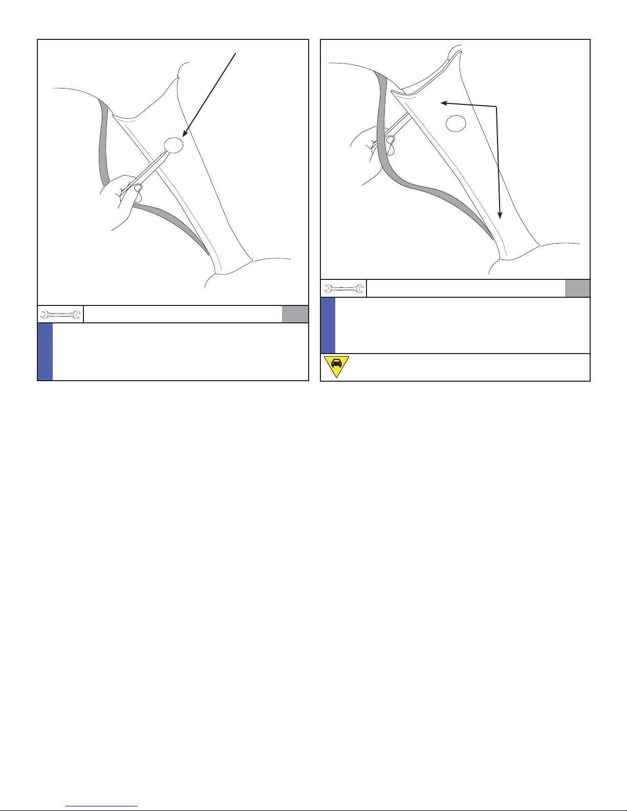
KIA Genuine Accessories (Vehicle Disassembly)
Access Cover and Phillips Screw
Pressure Clips
Trim Tool, Phillips Screwdriver
N
*Carefully pull the weatherstrip away from the driver’s
O
side “A” pillar.
T
*Remove the access cover and the single phillips
E
screw from the “A” pillar.
15
Trim Tool
N
*Starting at the top, use a trim tool and remove the
O
driver’s side “A” pillar trim panel by inserting the tool
T
behind the panel and prying outward to release the
E
(2) pressure clips.
CAUTION! Do not lose the (2) pressure clips.
16
Revision Date
3/9/2012
Page 8 of 27
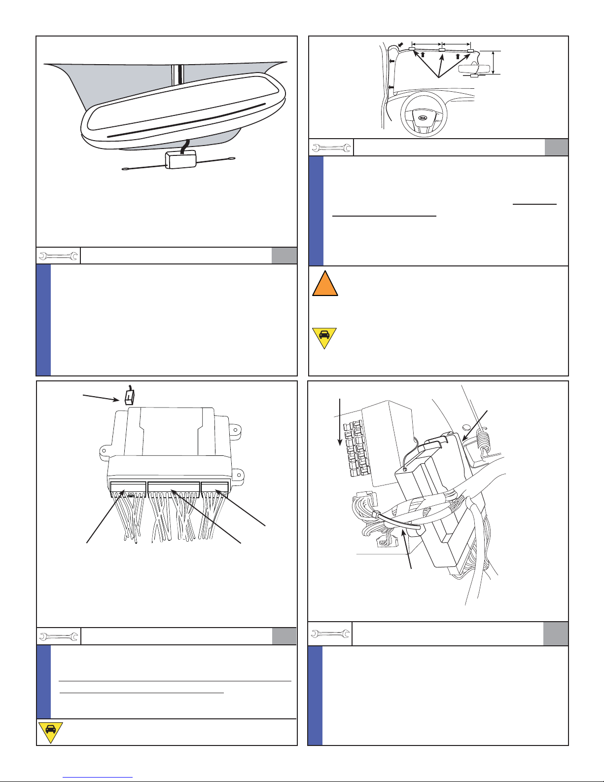
KIA Genuine Accessories (Installation)
9"
Foam Tape
9"
10"
Alcohol / Cleaner
*Clean the area of the windshield where the antenna
N
will be mounted with an alcohol-based glass cleaning
O
solution. Ensure the glass surface is completely dry.
T
E
*Mount the the dipole antenna to the windshield
approximately 0.5” below the mirrors lowest
attachement point and/or any windshield electronic
gridwork. Remove protective backing. Press fi rmly to
ensure a good glass to adhesive bond.
Antenna
Trim Tool, Wire Cutter
*Wrap the antena cable with (3) pieces of supplied
N
black foam tape to ensure that the antenna will stay
O
in place after routing, as shown above.
T
*Route the antenna cable vertically on the right hand
E
side of the mirror mount up to the headliner. Tuck
the cable behind the headliner and down the
“A” pillar. Use (3) small wire ties to secure the
antenna cable to the factory harness located within
1
the “A” pillar. Trim off excess wire ties.
WARNING! Air Bag system interference hazard.
DO NOT secure antenna cable to the Air Bag
!
components. Damage to the vehicle’s Air Bag
system may occur which could result in serious
physical injury.
CAUTION! If the vehicle is equipped with a sunroof, be careful not to place the wire ties around
the drain tube or the sunroof may not drain
properly.
Fuse Box
Hex Bolt & Nut
(Hidden From View)
2
*Route the antenna cable past the left side of the
N
dashboard and over to the fuse panel area.
O
*Plug the wire harness and the antenna cable into the
T
remote start module before mounting.
E
*Ensure all connectors are properly locked into posi-
tion.
CAUTION! Be careful not to bend/damage any of
the terminals inside the remote start module.
10-Pin
24-Pin16-Pin
Wire Tie
(Installed in Step 15)
*Torque Hex Nut to 52 inch pounds
3
N
O
T
E
Revision Date
3/9/2012
1/4” Drive Rachet, 3/8” Socket,
Torque Wrench, Wire Cutter
*Secure the upper right side tab of the remote start
module to the top hole in the factory brace supporting the fuse box with the supplied hex bolt and hex
nut. Secure the left side of the remote start module
to the factory harness with (1) large wire tie (Refer to
Step 15).
*Torque the hex nut to 52 inch pounds and trim off
excess wire tie.
Page 9 of 27
4
 Loading...