

KI Universal Overhead Storage Assembly Instructions Manual

Assembly Instructions
Universal Overhead Storage
September 2018

Universal Overhead Storage
Table of Contents
Universal Overhead Storage
Overhead Cabinet, Off-Module and On-Module Mounted Brackets ........................................3
Overhead Shelf, Off-Module and On-Module Mounted Brackets ............................................7
Radiused Front, Low & Regular Shelf...................................................................................11
Upmount Brackets ................................................................................................................13
2
cabinet back
Figure
Figure
stud
side panel
flange nut
Universal Overhead Storage
Assembly Instructions
Assemble units as described herein only. To do otherwise
may result in instability. All screws, nuts and bolts must be
tightened securely and must be checked periodically after
assembly. Failure to assemble properly, or to secure parts
may result in assembly failure and personal injury.
Overhead Cabinet, Off-Module
and On-Module Mounted Brackets
Assembly
Note: The following overhead
cabinet assembly steps refer to both
off-module and on-module cabinet
types. The type of mounting bracket
used determines the type of cabinet
being assembled. Also, if cabinets
are being pre-assembled and cabinet
type (off-module or on-module) is
to be determined at a later time, the
mounting brackets may be installed
at a later time.
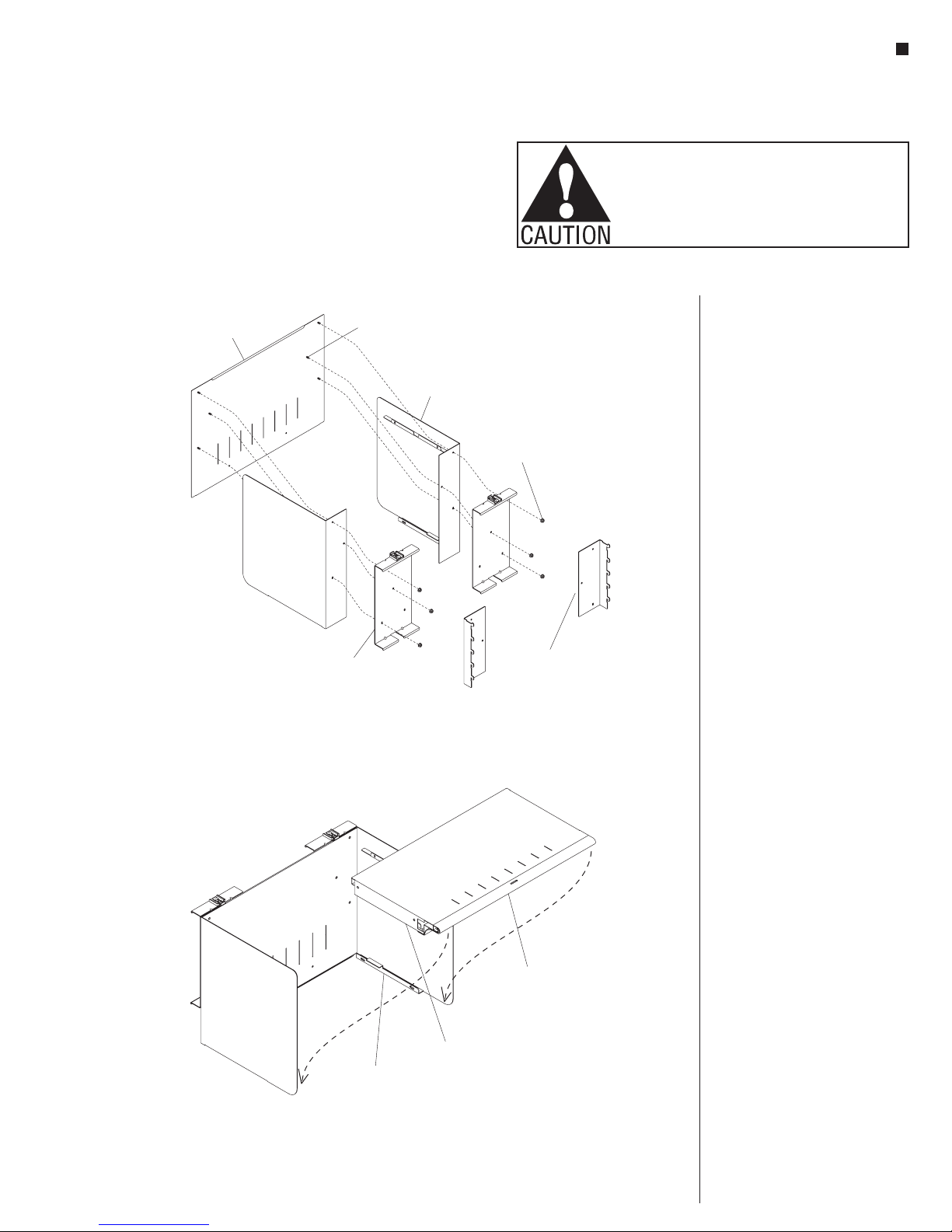
1. Assemble the cabinet back, side
panels and mounting brackets
(off-module or on-module) together
by inserting the holes in the side
panels (with support flanges facing
inward) and mounting brackets
through the studs on the cabinet
off-module
mounting bracket
on-module
mounting bracket
1
back. Loosely fasten the parts
together with six flange nuts as
shown. To avoid scratching side
panels during bottom shelf assembly
(step two), do not tighten flange nuts
at this time (Figure 1).
2. Set the bottom shelf into position
by locating the side flanges of the
bottom shelf over the lower support
flanges of the side panels (Figure 2).
bottom shelf
2
side flange
lower side panel
support flange
3

Universal Overhead Storage
Figure
-tapping screw
Figure 4
self
overhead top
t flange
Assembly Instructions
Assemble units as described herein only. To do otherwise
may result in instability. All screws, nuts and bolts must be
tightened securely and must be checked periodically after
assembly. Failure to assemble properly, or to secure parts
may result in assembly failure and personal injury.
3. Press the bottom shelf down and
adjust until the four screw holes in
the bottom shelf side flanges are
visible through the slots in the side
panel lower support flanges. From
under the cabinet, install four
#8 x 3/8” self-tapping screws through
the slots in the side panel support
flanges. Do not tighten completely. At
the lower rear of the cabinet, install
two #8 x 3/8” self-tapping screws
through the back and into the shelf.
Do not tighten completely (Figure 3).
4. Place the overhead top assembly
over the upper support flanges of the
side panels. Tap the top down into
place and align the round front edge
with the matching radius on the side
panel. Install and tighten four
#8 x 3/8” self-tapping screws through
the four larger oblong holes in the
rack and pinion door mechanism
inside the top assembly (Figure 4).
5. The recessed door can now be
pulled out and lowered to it’s closed
position. Adjust the bottom shelf so
the door hangs straight and flush
with the end panels. Tighten the four
screws under the bottom shelf at this
time. Using the door lock key (taped
to the inside of the top assembly for
shipping), engage the lock cam into
the locked position by turning the
key clockwise.
6. After the top and shelf have been
checked for proper alignment tighten
all hardware.
Note: For those users who wish
to retain the key in the lock when
storing the recessed door, there
is a set of door stops that may
be installed to prevent door from
opening past the key. If the door
is opened with the key in the lock,
damage to the overhead cabinet and/
or a key broken off in the lock may
result without door stops.
the installation of the door stop.
Remove the two rear #8 x 3/8” screws
(installed above). Press #8 x 3/4”
self-tapping screws through each
door stop and fasten the door stops
to the flipper door racks on each side
of the overhead where the two rear
screws were removed (Figure 4).
#8 x /
self-tapping screw
side panel
lower support flange
3
door stop
(optional)
3
#8 x /
"
4
-tapping
screw
3
"
8
assembly
bottom shelf
self
#8 x /
self-tapping
3
"
8
3
#8 x /
"
4
screw
rack and pinion
mechanism
7. To install recessed door stops,
open and store recessed door. Next,
pull door out about four inches,
enough to avoid interference with
4
side panel
upper suppor
Figure
12
mounting
bracket
overhead
lock
vertical slot
Universal Overhead Storage
Assembly Instructions
Assemble units as described herein only. To do otherwise
may result in instability. All screws, nuts and bolts must be
tightened securely and must be checked periodically after
assembly. Failure to assemble properly, or to secure parts
may result in assembly failure and personal injury.
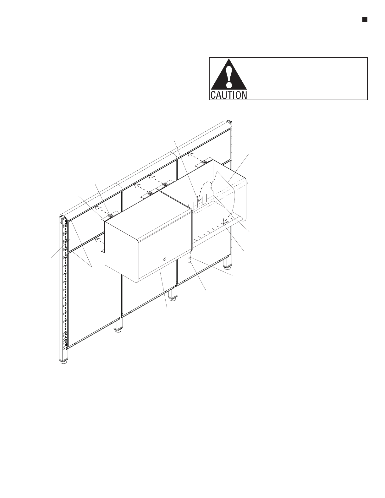
Off-Module Mounted Cabinets
8. Off-module mounted cabinets can
only be hung with the top aligned
shelf divider
(optional)
front hook
to a 12” tile. To make hanging
the overhead easier, remove the
tile or top cap directly above the
overhead. With the overhead locks
pulled out (toward the front of the
cabinet), hang the top and bottom
of the mounting bracket into the
tracks of the panel’s horizontal rail.
Make sure the cabinet is hanging
on the horizontal rail and not on
the tile. After the cabinet is hung
in the track, move it to the desired
position by gently lifting up while
sliding it. Secure the cabinet on the
tracks by pressing the overhead
locks into the track (Figure 5).
front slot
tile"
horizontal
rails
ganger
plate
assembly from the panel, push the
bottom of the cabinet straight up
about 1/4” and rotate the bottom out
toward you to about 30°. Pull the
cabinet straight out and down. Do
not force the side panel, damage to
Caution: To remove the cabinet
5
#8 x /
8
black screw
"
the top tooth may result.
9. When two or more cabinets are
off-module
overhead
installed next to each other, secure
them together with a ganger plate.
Fasten a ganger plate to the cabinet
bottoms with two #8 x 5/8” black
screws (Figure 5).
10. To install shelf dividers (optional),
first place the front hook of the
divider into the front slot of the
5
shelf. Then rotate the rear of the
divider down until the the tab snaps
into the vertical slot in the cabinet
back (Figure 5). To remove the
divider, press lightly on the cabinet
back to release the rear tab and
rotate it out.
5
 Loading...