

KI Unite System Assembly Instructions Manual
Assembly Instructions
®
Unite
Transaction Countertops
February 2017
System

Unite® System Transaction Countertops - Table of Contents
Assembly Instructions
Straight Transaction Countertop ����������������������������������������������������������������������������������������������������������������������������������� 3
Straight Transaction Countertop Adjacent to Change-of-Height Panel ������������������������������������������������������������������������� 5
Corner Transaction Countertop ������������������������������������������������������������������������������������������������������������������������������������ 6
Corner Transaction Countertop Adjacent to Change-of-Height Panel ��������������������������������������������������������������������������� 9
ADA Straight Transaction Countertop ������������������������������������������������������������������������������������������������������������������������� 10
ADA Straight Transaction Countertop Adjacent to Change-of-Height ADA Panel ������������������������������������������������������� 12
ADA Corner Transaction Countertop �������������������������������������������������������������������������������������������������������������������������� 13
ADA Corner Transaction Countertop Adjacent to Change-of-Height ADA Panel ��������������������������������������������������������� 16
2
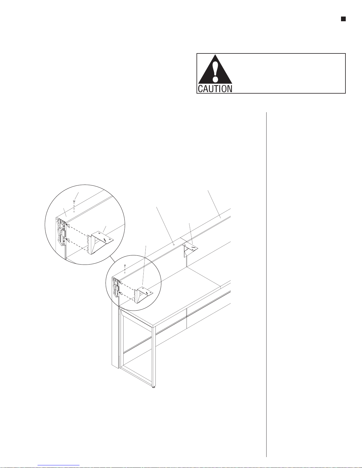
Figure 1
panel top
Unite® System - Straight Transaction Countertop
Assembly Instructions
Assemble units as described herein only. To do otherwise
may result in instability. All screws, nuts and bolts must be
tightened securely and must be checked periodically after
assembly. Failure to assemble properly, or to secure parts
may result in assembly failure and personal injury.
Standard 40” High Straight
Transaction Countertop Assembly
Overview: Installation below is
for a single rectangular transaction
countertop installed to a 40” high
Unite Panel� If the countertop length
is 60” or less, the transaction
countertop width must match the
width of the Unite Panel it installs
onto, and two design cantilever
brackets are used�
panel
top cap
rubber
button
cantilever bracket
Detail A
6” design
(left-hand)
rubber
button
6” design
cantilever bracket
(left-hand)
6” design
cantilever bracket
(right-hand)
cap
Note: If transaction countertop
length is over 60” (not illustrated
below), the countertop will span
the width of two Unite Panels and
three design cantilever brackets are
required�
1� Ensure that the Unite Panel top cap is
installed prior to attaching brackets
and transaction countertop� Install
two self-stick rubber buttons to
the top cap as illustrated� Spacing
of buttons is approximate, and
buttons prevent the countertop from
incidental contact with the top cap
(Figure 1)�
2� The 6” design cantilever brackets
are right- or left-hand in design, so
one style of bracket will install to the
left-hand side, and the other style
will install on the right-hand side of
the panel to support a transaction
countertop� They must be installed to
the inside (workstation side) of the
panel� To install a bracket, identify
the top slot of the panel vertical
post and insert the top tooth of the
appropriate cantilever design bracket
into that top slot� Engage all teeth
into slots in the vertical post, then
press down firmly to engage all teeth
into the slots� The horizontal top
of the bracket should be about 1/8”
above the top of the panel top cap�
Check bracket for full engagement
by pulling straight back firmly in a
horizontal motion (Figure 1 &
Detail A)�
3
Unite® System - Straight Transaction Countertop
Figure
(right-hand)
Assembly Instructions
Assemble units as described herein only. To do otherwise
may result in instability. All screws, nuts and bolts must be
tightened securely and must be checked periodically after
assembly. Failure to assemble properly, or to secure parts
may result in assembly failure and personal injury.
Standard 40” High Straight
Transaction Countertop Assembly
(cont.)
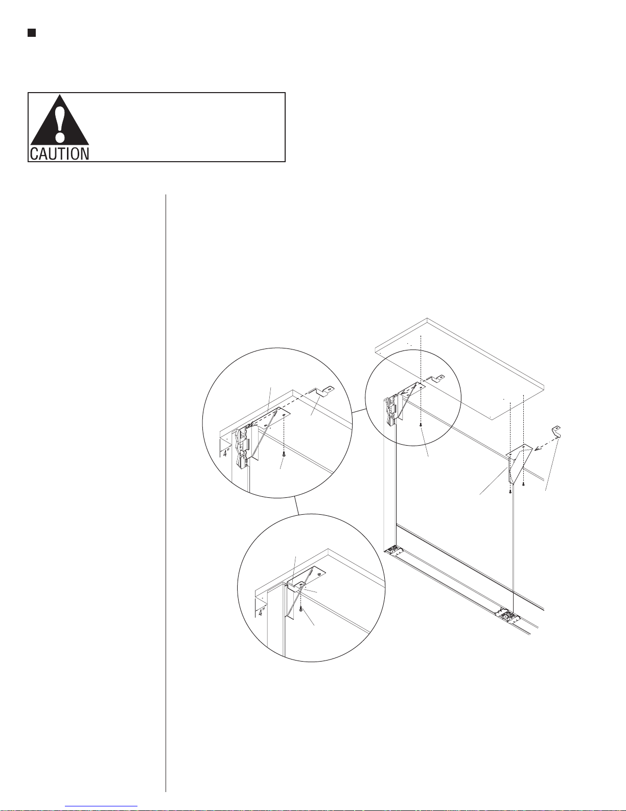
Note: The transaction countertop is
designed to be installed off-center on
the panel top� Per ADA guidelines,
only 4” of counter may extend into
the aisle side� The larger amount
of overhang is to extend over the
worksurface side�
3� After the cantilever brackets have
been installed to the workstation side
of the panel, position the transaction
countertop onto the brackets as
illustrated, with the smaller, 4”
countertop overhang into the aisle
side� Align mounting holes of the
brackets with the corresponding
pre-drilled holes in the underside
of the transaction countertop� Using
one #12 x 1” screw per bracket, at
the front side of the bracket (hole
closest the worksurface user),
secure the bracket to the transaction
countertop as illustrated (Figure 2
and Detail B)�
Note: Design bracket lock clips are
right- and left-hand by design, so
each must be paired with the design
cantilever bracket of the same hand
type�
4� Position a design lock clip as
illustrated (Detail B) and insert the
thin prong end of the clip into the top
panel notch, just above the top tooth
of the left-hand design cantilever
bracket� Fully inserted properly, the
mounting hole of the lock clip will
align over the unused mounting hole
in the cantilever bracket� Insert and
tighten the second #12 x 1” screw
to secure the clip over the cantilever
bracket, and to the transaction
countertop (Figure 2 & Details B & C)�
6” design
cantilever bracket
(left-hand)
2
#12 x 1”
screw
Detail B
design
lock clip
(left-hand)
design
lock clip
(left-hand)
#12 x 1”
screw
Detail C
6” design
cantilever bracket
(left-hand)
#12 x 1”
screw
transaction
countertop
6” design
cantilever bracket
(right-hand)
design
lock clip
5� Repeat step 4 above for the
right-hand design lock clip to
the right-hand design cantilever
bracket� Check and assure that all
four mounting screws are tight� The
transaction countertop must be snug
and no movement should be felt
(Figure 2 & Details B & C)�
4

Unite® System - Straight Transaction Countertop Adjacent to Change-of-Height Panel
Figure
Assembly Instructions
Assemble units as described herein only. To do otherwise
may result in instability. All screws, nuts and bolts must be
tightened securely and must be checked periodically after
assembly. Failure to assemble properly, or to secure parts
may result in assembly failure and personal injury.
Straight Transaction Countertop
Installed Adjacent to
Change-of-Height - Standard 40”
High Unite Panel
If a transaction countertop is
specified for installation adjacent to
a taller Unite Panel, the countertop
will be supplied with a notch to
end-of-run
trim
change-of-height
panel
accommodate the end-of-run
trim of the taller panel (Figure 3)�
A countertop designed to install
between two adjacent taller Unite
Panels will have a notch at both ends
(not shown)�
transaction
countertop
transaction
countertop
(one notch)
3
5
Unite® System - Corner Transaction Countertop
Figure 4
locking
tightening
Assembly Instructions
Assemble units as described herein only. To do otherwise
may result in instability. All screws, nuts and bolts must be
tightened securely and must be checked periodically after
assembly. Failure to assemble properly, or to secure parts
may result in assembly failure and personal injury.
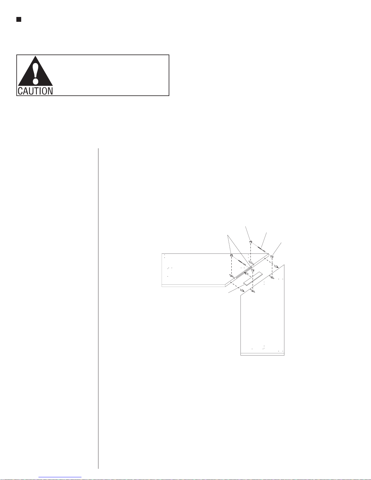
Corner Transaction Countertop Top Assembly
Note: The corner transaction counter
top comes disassembled and must
be joined together at the 45-degree
miter using KV joint fasteners�
Follow the directions below carefully�
1� Place the two corner counter surfaces
to be joined upside down on a soft
protective surface� Position the
surfaces as illustrated, then locate
and identify the KV joint fastener
components from the hardware pack
(Figure 4)�
2� Center the hardwood spline into the
routered slot in one corner top to be
joined� Press the two tops together,
aligning the hardwood spline� Check
to make sure the tops join together
completely with the spline in place�
If they do not, sand the spline if
necessary or adjust its location in the
slot (Figure 4)�
Important: For step 3 below, it is
important that the KV joint fastener
slots in the undersides of the
surfaces to be joined are aligned
perfectly�
Important: Each pound of pressure
on the tightening tool exerts 500
pounds of force on the joint�
Overtightening the KV fasteners will
cause the tops to delaminate�
corner
transaction
countertop
KV joint
fastner set
hardwood
spline
nut
draw
bolt
sleeve
3� Assemble KV fasteners by first
twisting a draw bolt into each
tightening nut a few turns, then press
each pair into a 7/8” hole and slot
in the underside of the transaction
countertop surfaces to be joined�
The flat-end of each draw bolt will be
visible in the 7/8” hole on one side
of the units being joined� One at a
time, position each locking sleeve as
illustrated and insert locking sleeves
into the 7/8” holes so that the slotted
sleeve engages the rounded collar on
the bolt (Figure 4)�
4� Tighten the nut with a tightening tool
or a nail-set� Check the front and
back edges, and more importantly
the top side of the joint for proper
alignment� The top-side joint should
be smooth and level with no gaps�
Adjust as necessary to achieve a
“seamless” look (Figure 4)�
6
corner
transaction
countertop
 Loading...