

KI Toggle SS Assembly Instructions Manual
Assembly Instructions
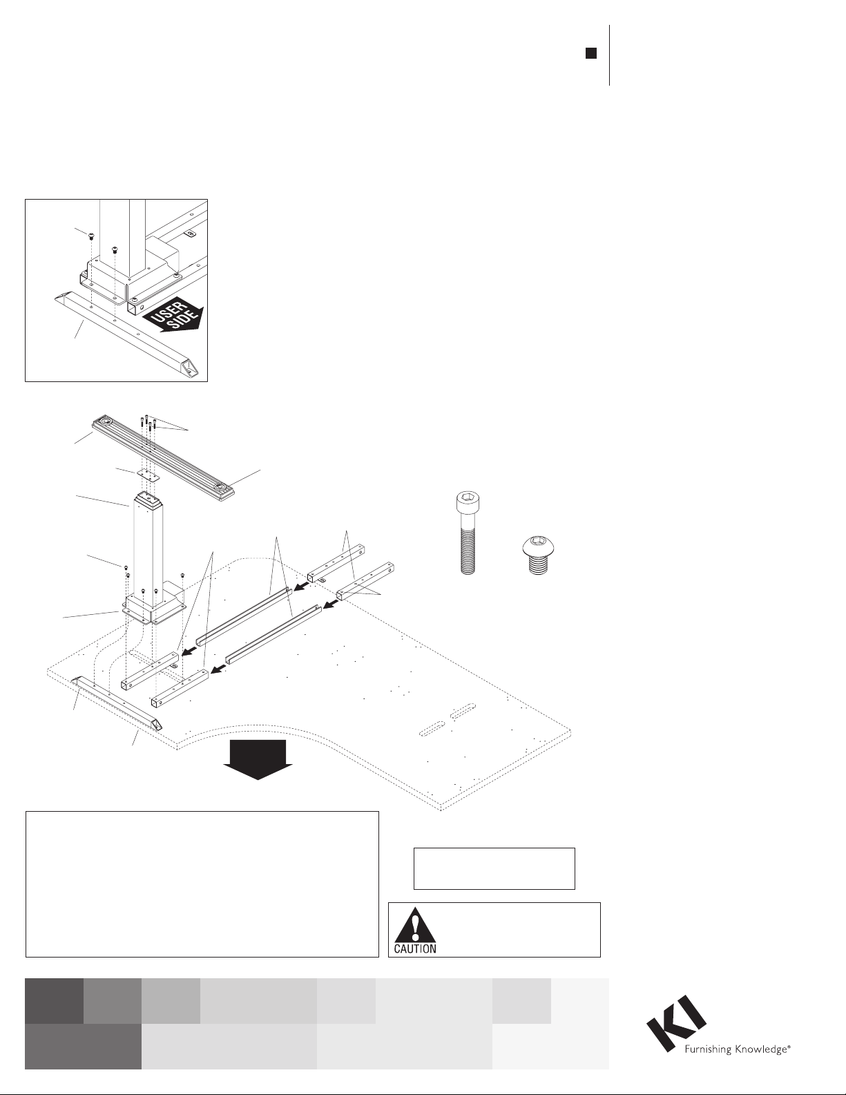
Figure
M6 x 35
machine screw
(at shor
mounting
Detail A
Toggle® Tables
Triple Motor C-Leg Height-Adjustable Square Shoe Base, Model SS
October 2019
M8 x 12
button-head
machine
screw
C-leg
end-support
tube
socket head
cap screws
cross-support
tubes (short)
adjustable
glide
leg-to-leg
spanners
(short)
USER
SIDE
C-leg
foot
leg column
assembly
M8 x 12
button-head
machine
screw
flange of
motor
housing
end-support
foot
plate
t end)
C-leg
tube
square shoe
tabletop (short end)
(shown for reference)
1
ATTENTION: Following assembly, table must be “zero set” prior
to being placed into service. Failure to do so can cause table to
malfunction.
Table “Zero Setting”: Press and hold the Up button for two seconds
then release. Next, press and hold the Down button until table has
reached its lowest position then release Down button. Then, press the
Down button again and hold for approximately 10 seconds. The table
now re-set at its “Zero Setting” position and is ready to operate.
cross-support
tubes (short)
1. Carefully remove contents from
packaging, set out on a soft, clean
surface and refer to Figures 1, 2 & 3
to identify the parts required for
assembly.
End C-Leg Assembly
(short end of table)
Note: Two different lengths of
cross-support tubes and leg-to-leg
spanners are supplied. The short
end of the table uses four short
cross-support tubes and two short
leg-to-leg spanners (Figure 2).
set screw
USER
holes
SIDE
M6 x 35
socket head
cap screw
Motor-Operated Furnishing
-FOR COMMERCIAL USE ONLY-
Assemble units as described herein only. To do otherwise
may result in instability. All screws, nuts and bolts must be
tightened securely and must be checked periodically after
assembly. Failure to assemble properly, or to secure parts
may result in assembly failure and personal injury.
M8 x 12
button-head
2. Start assembling the C-leg to be
placed on the short end of the
table by positioning two shorter
cross-support tubes (with mounting
tabs facing down and facing inwards),
and one C-leg end support tube in
position as illustrated in Figure 1.
Place a leg column assembly over
the three support tubes and align six
mounting holes of the leg column
mounting base with appropriate
mounting holes of the three tubes as
illustrated. The C-leg end support
tube contains three mounting holes
but only the two non-user side holes
are used. Make sure the tube has the
longer end with one unused mounting
hole facing the user side as illustrated
in Detail A. Using six M8 x 12 button
head machine screws torqued to
9.5 ft/lb, secure the flange of the leg
column to the three support tubes
(Figure 1).
3. Assemble the C-leg foot to the leg
column by first positioning a plastic
foot plate over the mounting location
on the leg column. The foot plate
must be oriented so the raised flange
faces into the column, to nest the foot
plate into place. Next, position a foot
over the foot plate and leg column as
illustrated, with the mounting holes
of the foot aligning with those of the
leg column. It is important that the
longer end of the C-leg foot face the
user side. Once the foot is correctly
oriented, secure the foot to the leg
column with four M6 x 35 socket
head cap screws. Torque to 7.5 ft/lb
(Figure 1).
4. Position the two shorter leg-to-leg
spanners with their channel openings
face up, then slide both spanners into
the open ends of the cross-support
tubes installed under the leg column
base. Next slide a cross-support tube
(matching the same length as at the
opposite end of the leg-to-leg
spanner) onto each end of the
leg-to-leg spanners (with mounting
tabs face down and facing inward).
Do not secure the support tubes to the
spanners with set screws at this time
(Figure 1).
Toggle® Tables - Triple Motor C-Leg Height-Adjustable Square Shoe Base, Model SS
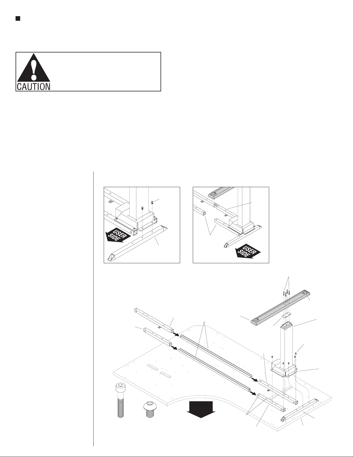
Figure 2
(at long end)
socket head
Detail B
30” x 60” x 48” Tables
Assembly Instructions
Assemble units as described herein only. To do otherwise
may result in instability. All screws, nuts and bolts must be
tightened securely and must be checked periodically after
assembly. Failure to assemble properly, or to secure parts
may result in assembly failure and personal injury.
End C-Leg Assembly
(long end of table)
Note: There are two different lengths
of cross-support tubes and leg-to-leg
spanners. The long end of the table
uses two short and two long
cross-support tubes and two long
leg-to-leg spanners. The two longer
support tubes must be installed to
the back, longer, non-user side of the
table (Figure 2).
1. Start assembling the C-leg to be
placed on the long end of the
table by positioning one shorter and
one longer cross-support tube (with
mounting tabs facing down and facing
inwards), and one C-leg end support
tube in position as illustrated in
Figure 2. The longer cross-support
tube must be positioned to the back,
longer, non-user side of the table.
Place a leg column assembly over
the three support tubes and align six
mounting holes of the leg column
mounting base with appropriate
mounting holes of the three tubes as
illustrated. The C-leg end support
tube contains three mounting holes
but only the two non-user side holes
are used. Make sure the tube has the
longer end with one unused mounting
hole facing the user side as illustrated
in Detail B. Using six M8 x 12 button
head machine screws torqued to
9.5 ft/lb, secure the flange of the leg
column to the three support tubes
(Figure 2).
2. Assemble the C-leg foot to the leg
column by first positioning a plastic
foot plate over the mounting location
on the leg column. The foot plate
must be oriented so the raised flange
faces into the column, to nest the foot
plate into place. Next, position a foot
over the foot plate and leg column as
illustrated, with the mounting holes
of the foot aligning with those of the
leg column. It is important that the
longer end of the C-leg foot face the
user side. Once the foot is correctly
oriented, secure the foot to the leg
column with four M6 x 35 socket
head cap screws. Torque to 7.5 ft/lb
(Figure 2).
2
Note: If the table being assembled
is 30” x 48” x 60” or 30” x 60” x 48”,
the leg-to-leg spanner on the longer,
user side of the table is not required
and must NOT be installed. Unused
spanner(s) may be disposed of
(Detail C).
3. Position the two longer leg-to-leg
spanners with their channel openings
face up, then slide both spanners into
button-head
C-leg
end-support
tube
cross-support
tube (short)
M6 x 35
cap screw
M8 x 12
button-head
machine screw
M8 x 12
machine
screw
cross-support
tube (long)
the open ends of the cross-support
tubes installed under the leg column
base. Next slide a cross-support tube
(matching the same length as at the
opposite end of the leg-to-leg
spanner) onto each end of the
leg-to-leg spanners (with mounting
tabs face down and facing inward).
Do not secure the support tubes to the
spanners with set screws at this time
(Figure 2).
cross-support
tubes (short)
with no
leg-to-leg
spanner
Detail C - 30”x 48” x 60” &
leg-to-leg
spanners
(long)
USER
USER
SIDE
SIDE
C-leg
foot
set screw
holes
cross-support
tube (short)
leg-to-leg
spanner
(short)
foot
plate
cross-support
tube (long)
M6 x 35
socket head
cap screws
adjustable
glide
leg column
assembly
M8 x 12
button-head
machine
screw
mounting
flange of
motor
housing
C-leg
end-support
tube
square shoe
tabletop (long end)
(shown for reference)
Toggle® Tables - Triple Motor C-Leg Height-Adjustable Square Shoe Base, Model SS
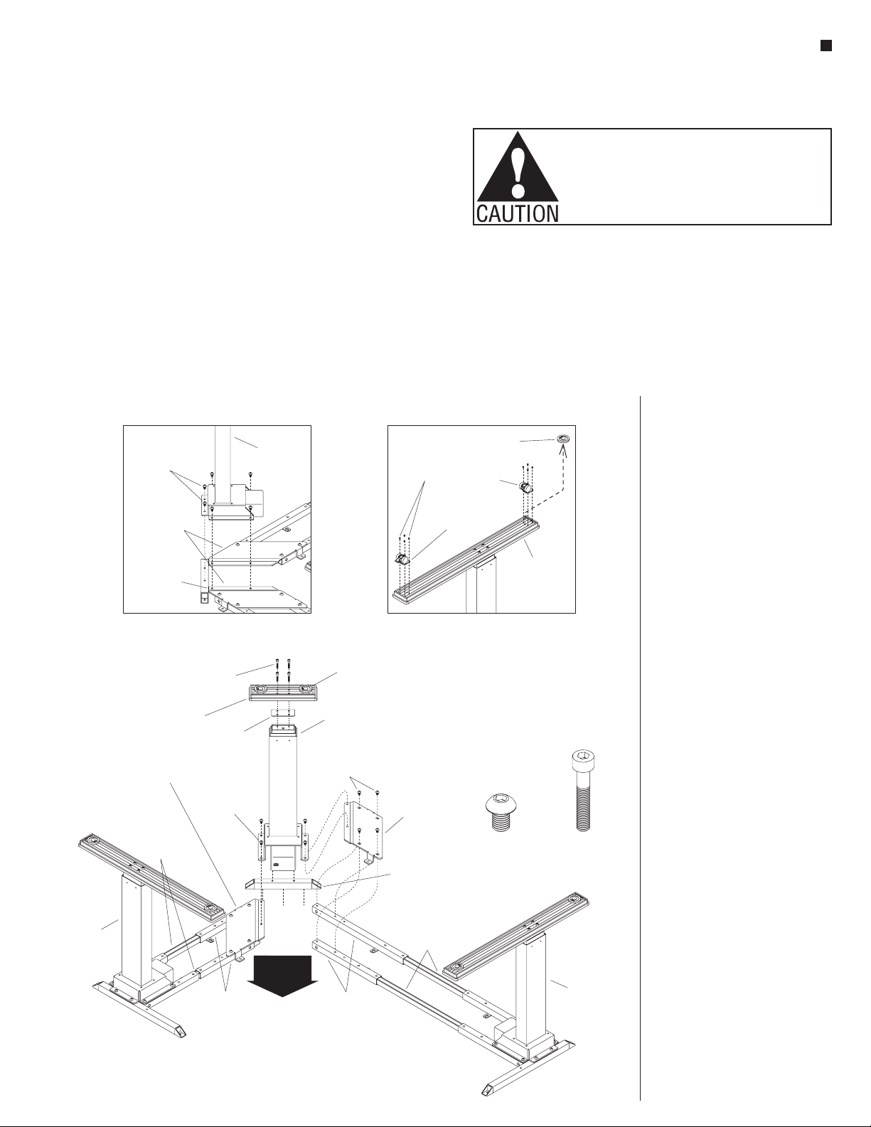
Figure 3
socket head
Detail D
Detail E
Assembly Instructions
Assemble units as described herein only. To do otherwise
may result in instability. All screws, nuts and bolts must be
tightened securely and must be checked periodically after
assembly. Failure to assemble properly, or to secure parts
may result in assembly failure and personal injury.
end
C-Leg
M8 x 12
button-head
machine screws
middle-support
brackets
middle-support
bracket
flange
socket head
cap screw
square
shoe foot
middle-support
bracket
(right-hand)
leg-to-leg
spanners
(short)
M6 x 35
foot
plate
M8 x 12
button-head
machine
screw
cross-support
tubes (short)
Corner Leg Assembly
Note: Middle-support brackets are
left- and right-handed. Brackets are
each designed to install to a specific
side of the corner leg column.
Take care and follow directions
below when installing brackets.
If brackets are not installed to the
proper left- or right-hand location,
leg
column
adjustable
glide
corner leg
column
M8 x 12
button-head
machine screws
USER
USER
SIDE
SIDE
cross-support
tubes (short & long)
Torx head
screws
locking
caster
bracket
(left-hand)
tube
leg-to-leg
spanners
(long)
3
8
#10-24 x /
middle-support
square shoe
end-support
corner leg column will not secure to
the brackets and disassembly and
reassembly will be required.
1. Orient and place each
middle-support bracket over the
cross-support tube assembly
with flange facing the corner leg
installation location as illustrated.
adjustable
"
glide
non-locking
caster
M8 x 12
button-head
machine screw
foot
M6 x 35
cap screw
end
C-Leg
Align the holes of the middle
support bracket with the support
tube mounting holes and secure with
four M8 x 12 button-head machine
screws (Figure 3).
2. Place the square shoe
end-support tube between the two
cross-support tube assemblies as
illustrated in Figure 3.
3. Position the corner leg column over
the square shoe end-support tube
and two middle-support bracket’s
flanges, then align six mounting
holes of the leg column with
appropriate mounting holes of the
two brackets and tube as illustrated
in Figure 3 and Detail D. Using
six M8 x 12 button head machine
screws torqued to 9.5 ft/lb, secure
the flange of the leg column to the
square shoe end-support tube and
middle-support brackets (Figure 3 &
Detail D).
4. Assemble the square shoe foot to
the leg column by first positioning a
plastic foot plate over the mounting
location on the leg column. The foot
plate must be oriented so the raised
flange faces into the column, to
nest the foot plate into place. Next,
position the square shoe foot over
the foot plate and leg column as
illustrated, with the mounting holes
of the foot aligning with those of the
leg column. Secure the foot to the
leg column with four M6 x 35 socket
head cap screws. Torque to
7.5 ft/lb (Figure 3).
5. If casters are required, twist all
adjustable glides out of the square
shoe and C-leg feet. Locking and
non-locking casters are supplied.
Locking casters should be located
toward the front, user side of the
table for easy access while the
non-locking casters are located to the
back. Using four #10-24 x 3/8” Torx
screws, carefully secure the casters
to the foot (Detail E).
3
Toggle® Tables - Triple Motor C-Leg Height-Adjustable Square Shoe Base, Model SS
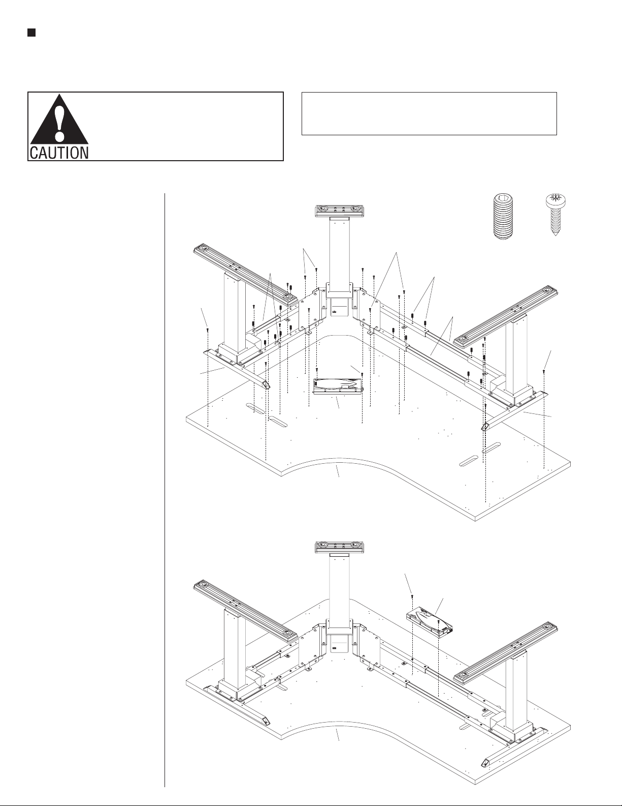
Figure
M5.5 x 22
M5.5 x 22
base
Figure 5
Assembly Instructions
Assemble units as described herein only. To do otherwise
may result in instability. All screws, nuts and bolts must be
tightened securely and must be checked periodically after
assembly. Failure to assemble properly, or to secure parts
may result in assembly failure and personal injury.
1. Carefully turn tabletop upside down
on a soft, protective surface and
set the base assembly onto the
underside of the top. Position one
base end, so base mounting holes
align with tabletop mounting holes,
and secure base to top using six
M5.5 x 22 pan head screws. Slide
the other base end into position by
adjusting the cross-support tubes
to align base mounting holes to the
tabletop holes and secure with six
M5.5 x 22 pan head screws. Next,
secure the corner base mounting
holes to the tabletop mounting holes
using six M5.5 x 22 pan head screws
(Figure 4).
2. Insert and tighten sixteen
M10 x 25 set screws as illustrated,
through the cross support tubes and
down to the leg-to-leg spanners.
Torque to 4.5 ft/lb to secure
(Figure 4).
pan head
screw
end
leg-to-leg
spanners
(short)
CAUTION: If Channels (Wire Troughs) are used they are not to be used for routing
extension cords. Power supply cords are not to be routed across or through more
than one complete unit/worksurface.
M5.5 x 22
pan head
screws
M5.5 x 22
pan head
screw
control
box
M5.5 x 22
pan head
screws
M10 x 25
set screws
leg-to-leg
spanners
(long)
M10 x 25
set screw
pan head
screw
M5.5 x 22
pan head
screw
base
end
3. The control box can be mounted
in one of two locations, center
corner in front of the cross tube
assemblies (Figure 4) or between
the cross-tube assemblies on the
longer side of the table (Figure 5).
If desired, the control box can be
used as a template underneath the
tabletop to mark, then drill a hole
for an alternative mounting location.
Position the control box over the
pre-drilled mounting hole and secure
using two M.5 x 22 pan head screws
(Figures 4 & 5).
square shoe
tabletop
4
M5.5 x 22
pan head
screw
control
box
square shoe
tabletop
4
 Loading...