

KI 810, System 3000 Installation Instructions Addendum
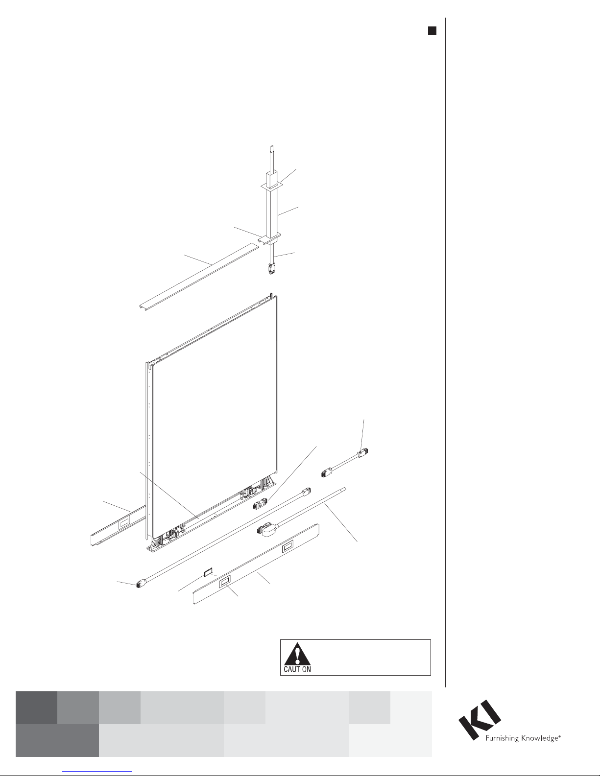
panel rigid wireway
electrical raceway cover
power-pass-through harness
Figure 1 - Parts Identification
Addendum Installation Instructions
System 3000 Panel System
"810" 10-Wire Electrical System
January 2011
ceiling trim plate
top feed power pole
infeed top cap
panel top cap
filler plate
bezel
top feed wire harness
duplex receptacle
electrical raceway cover
Assemble units as described herein only. To do otherwise
may result in instability. All screws, nuts and bolts must be
tightened securely and must be checked periodically after
assembly. Failure to assemble properly, or to secure parts may
result in assembly failure and personal injury.
panel-to-panel
jumper
universal
base power infeed
Suggested Electrical Installation
Sequence - Read Before
Beginning Installation
1. Familiarize yourself with all
electrical components before
beginning installation.
Warning: Assembly of all
mechanical frame components
must be completed before making
any electrical connections. All
electrically connected furnishings
must also be mechanically
connected.
2. Before installing electrical
components, consult inspector
or authorities for local codes.
Connection to building power
supply may be made ONLY
after all panel wiring has been
completed. Building connections
must be made only by a licensed
electrician following local codes at
the building site.
3. Each circuit must be individually
protected with a 120-volt, 20-amp
circuit breaker device which will
provide disconnect and overload
protection.
Installation Instructions
1. Familiarize yourself with the
electrical parts and the locations of
top feeds or base feeds.
2. Install the top feed harness in the
appropriate panel as the panels are
being installed.
3. If base feed harnesses are to be
located between a panel and a
building wall, install the base
feed harness as the panels are
being installed. Leave access for
the electrician to make the final
hardwire connection of the base
feed harness to the building.
4. Install all of the panel-to-panel
jumpers and the
power-pass-through harness as
shown on the space-planning
layout. Be sure all connections
are tight.
5. Install all duplex receptacles in the
locations shown in the
space-planning layout.
6. Check the electrical continuity at
the furthest point from the power
infeed location.

System 3000 Panel System - "810" 10-Wire Electrical System
Addendum Installation Instructions
Assemble units as described herein only. To do otherwise
may result in instability. All screws, nuts and bolts must be
tightened securely and must be checked periodically after
assembly. Failure to assemble properly, or to secure parts may
result in assembly failure and personal injury.
Panel-To-Panel Electrical
Connections 810-Universal
1. Power is carried between adjacent
panels by panel jumpers (See Details
A-F, for which jumper to use with
different panel configurations).
2. Attach the panel jumpers to the
plug-in ports that are on the end of
each panel wireway by pushing them
together until they are locked.
3. If connecting power through a
non-powered panel, plug the correct
length power-pass-through into the
adjacent panel wireways
(See Details G-J).
4. Check the continuity from
panel-to-panel with a voltmeter.
A
YOU USE:
(1) 17” PANEL JUMPER
P10
C
YOU USE:
(2) 17” PANEL JUMPERS
E
YOU USE:
(1) 20” PANEL JUMPER
P10
P10
P10
G
P10
YOU USE:
(1) POWER-PASS-THROUGH THE SAME
SIZE AS THE NON-POWERED PANEL
NP
I
NP NP
YOU USE:
(1) POWER-PASS-THROUGH ONE SIZE
LARGER THAN THE NON-POWERED PANEL,
(WITH EXCEPTION OF 60 NP PANELS)
P10
P10
P10
NP
B
YOU USE:
(1) 17” PANEL JUMPER
D
P10
YOU USE:
(3) 17” PANEL JUMPERS
F
P10
P10
NOTE:
YOU MUST SPECIFY EITHER
THE 4-4-2 10-WIRE SYSTEM,
OR THE 6-2-2 10-WIRE
SYSTEM. THE TWO SYSTEMS
CANNOT BE MIXED.
H
P10
YOU USE:
(1) POWER-PASS-THROUGH THE SAME
SIZE AS THE NON-POWERED PANEL
J
P10 P10
NP
YOU USE:
(1) POWER-PASS-THROUGH ONE SIZE
LARGER THAN THE NON-POWERED PANEL,
(WITH EXCEPTION OF 60 NP PANELS)
P10
P10
P10
P10
P10
NP P10
NP
P10
2
Details A - J
System 3000 Panel System - "810" 10-Wire Electrical System
Addendum Installation Instructions
Assemble units as described herein only. To do otherwise
may result in instability. All screws, nuts and bolts must be
tightened securely and must be checked periodically after
assembly. Failure to assemble properly, or to secure parts may
result in assembly failure and personal injury.
Duplex Receptacle Installation
1. Duplex receptacles should be
rigid wireway
connected after wireways are installed
but BEFORE power is connected to
the building supply.
2. Follow the installation drawings to
install the duplex receptacles for
the circuit desired in the correct
locations.
3. Position the receptacle on either end
of the wireway as shown (depending
on location desired), matching the
N
symbol to the same orientation
on both the receptacle and wireway.
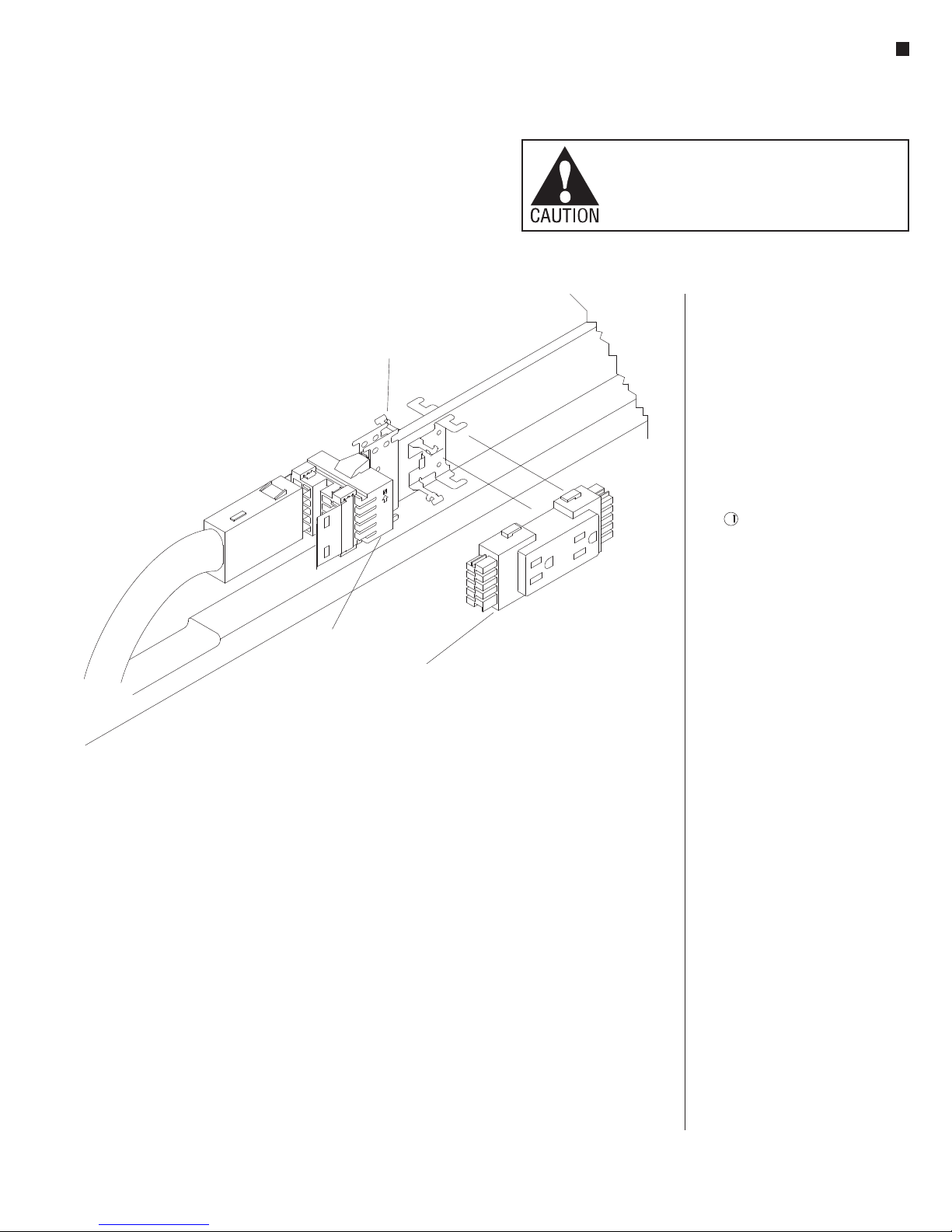
Figure 2
wireway
inner socket
duplex receptacle
4. Align the receptacle so the end is
in line with the inner socket on the
wireway (Figure 2).
5. Push the receptacle back against the
mounting plate (Figure 2).
6. Slide the receptacle to the side so the
end terminals slide into the wireway
inner socket (Figure 2).
7. Receptacle is properly seated when
the catch clip on the wireway
is between the wedges on the
receptacle.
Removing Receptacle
1. Slightly lift the catch clips on the top
and bottom of the receptacle (Figure
3) and slide the receptacle away from
the socket on the wireway.
2. Pull the receptacle away from
the wireway once the end of the
receptacle clears the wireway socket.
Note: Receptacles must be installed
BEFORE raceway covers. Covers
must be removed to add, move, or
change receptacles.
Caution: This step should be done
with great care. Do not insert a
screwdriver into electrical outlet. Do
not remove the receptacle while it is
under load.
3
 Loading...