

KI RT Assembly Instructions Manual
Assembly of Table
Tools Required:
·#2 Phillips Screwdriver
·#3 Phillips Screwdriver
· 5mm Hex Key (provided)
: Before discarding any packaging
confirm all components received against the
packing list. Table assembly should be done
onaclean flat floor.
(Figure1)
(Figure1)
(Figure1)
(Figure1)
Note
Note
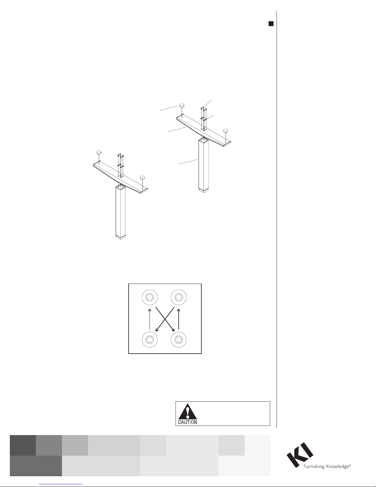
Assemble Feet To Columns
:When tightening the M8 screws, first
twistin all fourscrews“finger tight”, then
tighten the screwsone quarter turnatatime
using adiagonal tightening pattern as shown
in Detail A. Repeat the diagonal pattern until
all fourscrewsare tight (DetailA&Figure1).
1. Setthe column on endwith thesmaller
(inner) square tubeon the floor.The
threaded holesvisible on the endof the
column will be in a rectangular (not square)
pattern .
2. Placethe foot overthe column endso
thecolumn fits into the square hole in the
foot.The slottedholesinthe foot should line
up with the fourholesin the column end. If
not the foot needs to be removedand
repositioned at 90 degrees .
3. Attach the foot using fourM8x20mm
screws and four8mm flat washers .
4. Threadleveling glide into the holesat
theendsofthe foot .
5. Repeatsteps 1 through 4 for the
second foot andcolumn.
Detail A
Assembly Instructions
WorkUp Electric Height Adjustable Tables
Model RT
Assembly of Table
Tools Required:
·#2 Phillips Screwdriver
·#3 Phillips Screwdriver
· 5mm Hex Key (provided)
: Before discarding any packaging
confirm all components received against the
packing list. Table assembly should be done
onaclean flat floor.
Note
Note
:When tightening the M8 screws, first
twistin all fourscrews“finger tight”, then
tighten the screwsone quarter turnatatime
using adiagonal tightening pattern as shown
in Detail A. Repeat the diagonal pattern until
all fourscrewsare tight (DetailA&Figure1).
Assembly Instructions
WorkUp Electric Height Adjustable Tables
Model RT
Assembly Instructions
WorkUp Adjustable Table
Model RT
November 2016
Figure 1
leveling glide
Detail A
foot
column
M8x20mm
screw
flat
washer
Assemble units as described herein only. To do otherwise
may result in instability. All screws, nuts and bolts must be
tightened securely and must be checked periodically after
assembly. Failure to assemble properly, or to secure parts
may result in assembly failure and personal injury.
Tools Required
• #3 Phillips Screwdriver
• 5mm Hex Key
Note: Before discarding any
packaging confirm all components
received against the packing list. Table
assembly should be done on a clean
flat floor.
Note: When tightening the M8
screws, first twist in all four screws
“finger tight”, then tighten the screws
one quarter turn at a time using
a diagonal tightening pattern as
shown in Detail A. Repeat the diagonal
pattern until all four screws are tight
(Figure 1 & Detail A).
Assemble Feet To Columns
1. Set the column on end with the
smaller (inner) square tube on the
floor. The threaded holes visible
on the end of the column will
be in a rectangular (not square)
pattern (Figure 1).
2. Place the foot over the column
end so the column fits into the
square hole in the foot. The
slotted holes in the foot should
line up with the four holes in the
column end. If not the foot needs
to be removed and repositioned at
90 degrees (Figure 1).
3. Attach the foot using four
M8 x 20mm screws and four
8mm flat washers, tightening
each screw one quarter turn
at a time in a diagonal pattern
until all four screws are tight
(Figure 1 & Detail A).
4. Thread leveling glides into the
holes at the ends of the foot
(Figure 1).
Note: If the roller foot option
was purchased, one foot will have
pre-assembled rollers.
5. Repeat steps 1 through 4 for
the second foot and column
(Figure 1).
WorkUp Adjustable Table - Model RT
Assembly Instructions
Assemble units as described herein only. To do otherwise
may result in instability. All screws, nuts and bolts must be
tightened securely and must be checked periodically after
assembly. Failure to assemble properly, or to secure parts
may result in assembly failure and personal injury.
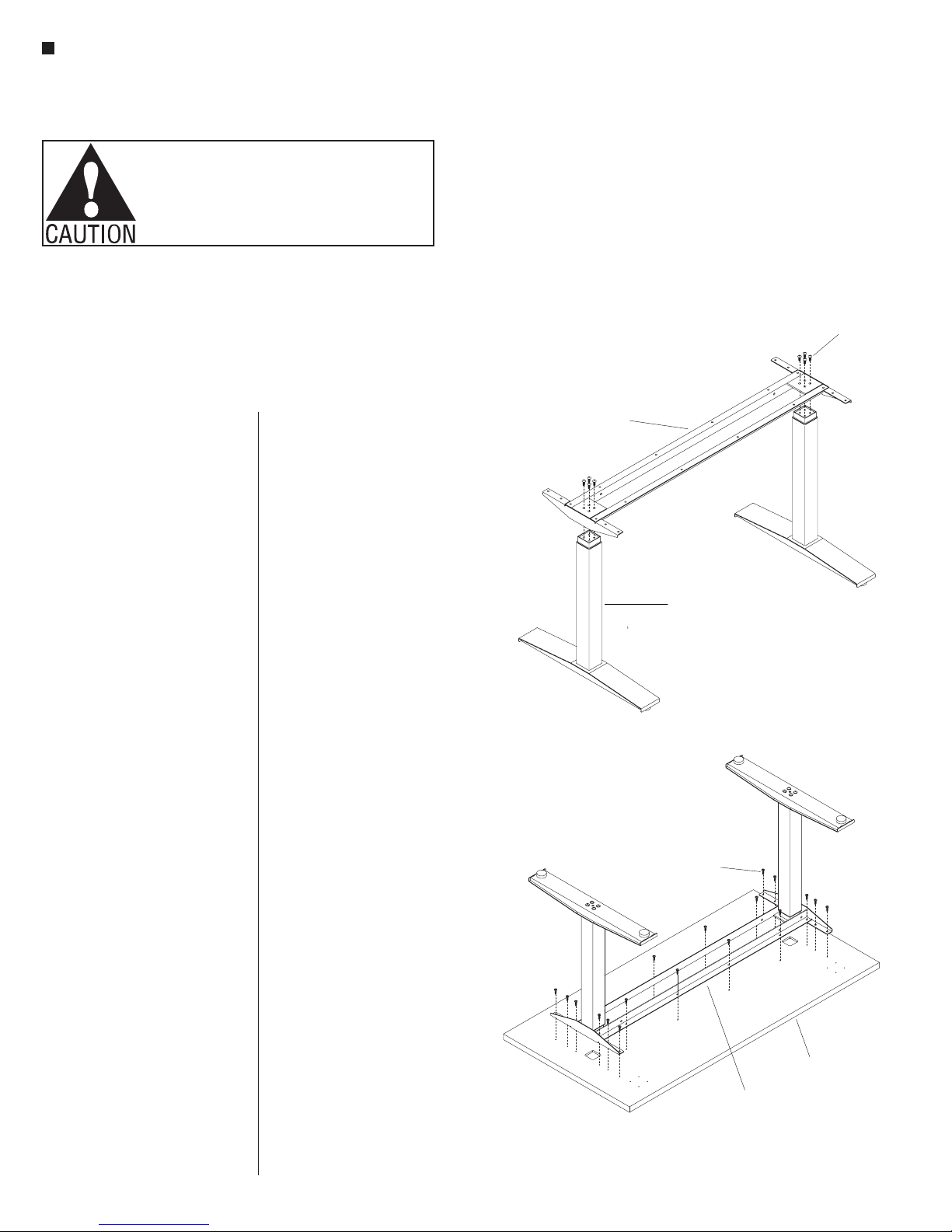
Assemble Columns To
Worksurface Support
1. With the foot/column assembly
standing upright on the glides,
align the four holes in one end of
the worksurface support with the
four holes in the small end of the
foot/column (Figure 2).
2. Attach the worksurface support
using four M8 x 20mm screws,
tightening each screw one quarter
turn at a time in a diagonal pattern
until all four screws are tight
(Figure 2 & Detail A).
3. Attached the second foot/column
in the same manner (Figure 2).
Note: Before attaching the
worksurface be sure the feet
are parallel to each other and
perpendicular to the worksurface
support. If not, loosen the attachment
screws, reposition the feet and
re-tighten the screws.
Assemble Worksurface
Note: The worksurface is pre-drilled
for installation of all components.
1. To avoid scratching the
worksurface place it with the top
side down on a soft protective
material.
2. Place the worksurface support
with columns on the drilled face
of the worksurface so the heads of
the M8 bolts set into the pockets
milled in the worksurface. The
worksurface support should now
be flush with the worksurface
(Figure 3).
3. Move the worksurface support
with columns slightly to align
the holes in the worksurface with
those in the worksurface support
(Figure 3).
4. Attach the worksurface using
#12 x 1” tapping screws in each
available hole (Figure 3).
5. Carefully invert the table to its
upright position. Caution: The
table is very heavy. Two or more
people are required to turn table
upright.
6. Adjust leveling glides to level
the table.
M8x20mm
screw
worksurface
support
foot/column assembly
Figure 2
#12x1”
screw
worksurface
worksurface
support
Figure 3
2
 Loading...