

KI HF Assembly Instructions Manual
Assembly Instructions
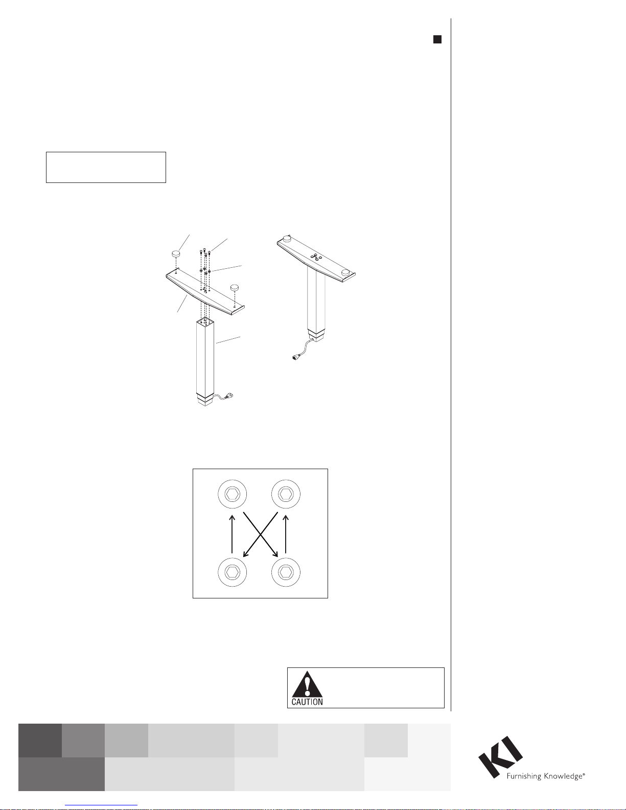
Figure 1
WorkUp Adjustable Table
Model HF
April 2017
Motor-Operated Furnishing
-FOR COMMERICAL USE ONLY-
leveling
foot
glide
M8 x 18mm
screw
flat
washer
column
Tools Required
• #2 Phillips Screwdriver
• #3 Phillips Screwdriver
• 5mm Hex Key
Note: Before discarding any
packaging confirm all components
received against the packing list.
Table assembly should be done on a
clean flat floor.
Note: When tightening the
M8 x 18mm screws, first twist in
all four screws “finger tight”, then
tighten the screws one quarter turn
at a time using a diagonal tightening
pattern as shown in Detail A. Repeat
the diagonal pattern until all four
screws are tight (Figure 1 &
Detail A).
Feet To Columns Assembly
1. Set the column on end with the
smaller (inner) square tube on the
floor. The threaded holes visible
on the end of the column will be in
a rectangular (not square) pattern
(Figure 1).
2. Place the foot over the column end
so the column fits into the square
hole in the foot. The slotted holes
in the foot should line up with the
four holes in the column end. If not
the foot needs to be removed and
repositioned at 90 degrees
(Figure 1).
Detail A
Assemble units as described herein only. To do otherwise
may result in instability. All screws, nuts and bolts must be
tightened securely and must be checked periodically after
assembly. Failure to assemble properly, or to secure parts
may result in assembly failure and personal injury.
3. Attach the foot using four
M8 x 18mm screws and four 8mm
flat washers, tightening each screw
one quarter turn at a time in a
diagonal pattern until all four screws
are tight (Figure 1 & Detail A).
4. Thread leveling glide into the holes
at the ends of the foot (Figure 1).
Note: If the roller foot option was
purchased, one foot will have
pre-assembled rollers.
5. Repeat steps 1 through 4 for the
second foot and column (Figure 1).
WorkUp Adjustable Table - Model HF
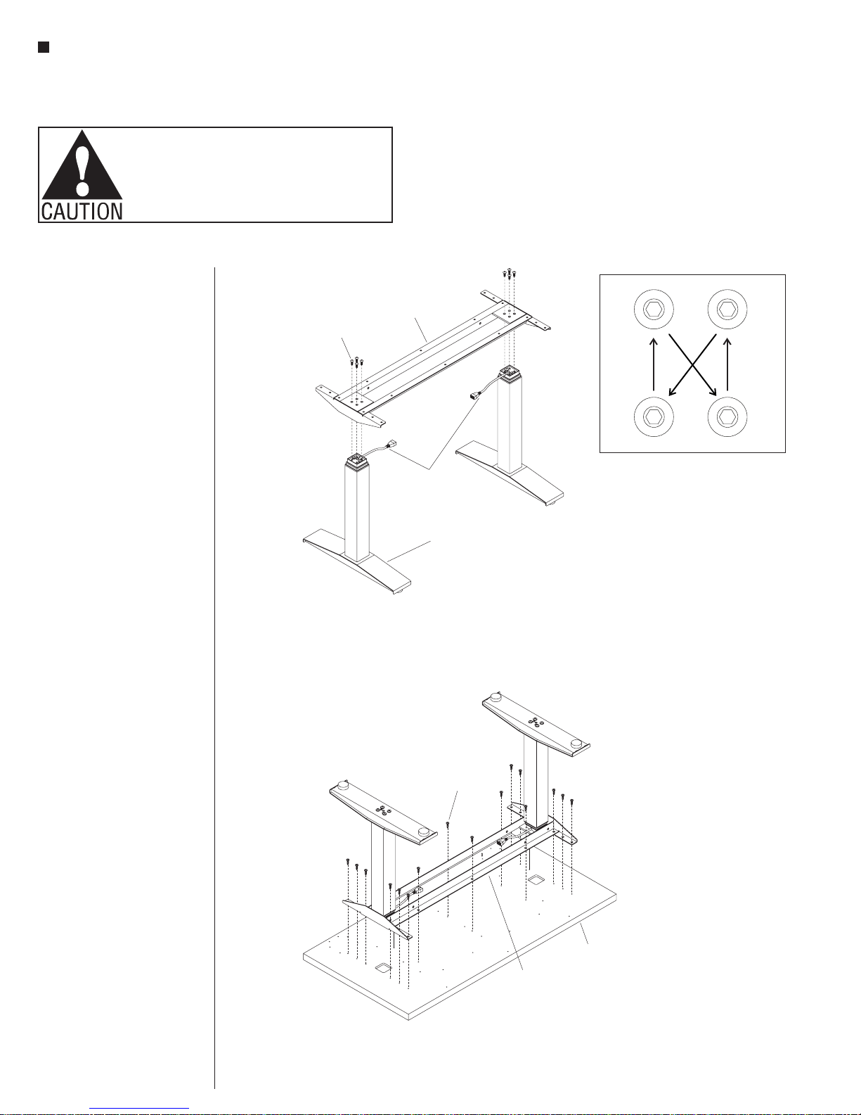
Figure 3
Figure 2
Assembly Instructions
Assemble units as described herein only. To do otherwise
may result in instability. All screws, nuts and bolts must be
tightened securely and must be checked periodically after
assembly. Failure to assemble properly, or to secure parts
may result in assembly failure and personal injury.
Columns to Worksurface
Support Assembly
1. With the assistance of a
second person, hold both foot/
column assemblies in the
upright position, orienting the
two column cables inward as
illustrated (Figure 2).
2. Position the worksurface support
onto the foot/column assemblies
and allign the four holes in one
end of the support with the four
holes in the column (Figure 2).
3. Attach the worksurface support to
the column using four
M8 x 18mm screws until
snug, then tighten each screw
one quarter turn at a time in a
diagonal pattern until all four
screws are tight (Figure 2 &
Detail A).
M8 x 18mm
screw
worksurface
support
Detail A
column
cables
foot/column
assembly
4. Attach the second foot/column in
the same manner (Figure 2).
Worksurface Assembly
Note: Except for the “P” shaped
cable clamps, the worksurface is
pre-drilled for installation of all
components.
1. To avoid scratching the table top,
place it with the top side down on
a soft protective material
(Figure 3).
2. Place the worksurface support
with columns on the drilled face
of the table top so the heads
of the M8 bolts set into the
pockets milled in the table top.
The worksurface support should
now be flush with the table top
(Figure 3).
3. Move the worksurface support
with columns slightly to align
the holes in the table top with
those in the worksurface support
(Figure 3).
#12 x 1”
screw
table top
worksurface
support
assembly
4. Attach the table top using
#12 x 1” tapping screws in each
available hole (Figure 3).
2

11
Figure
#10 x /”
16
screw
keypad
4
plastic wire
trough
(optional)
worksurface
support
table top
#12 x 1”
screws
control
box
WorkUp Adjustable Table - Model HF
Assembly Instructions
Assemble units as described herein only. To do otherwise
may result in instability. All screws, nuts and bolts must be
tightened securely and must be checked periodically after
assembly. Failure to assemble properly, or to secure parts
may result in assembly failure and personal injury.
Electric Controls Installation
Note: The keypad may be
mounted to the underside of table
top, at pre-drilled locations on the
right- or left-hand side.
1. Attach the keypad at the left- or
right-hand front edge of the table
using (two screws for standard
keypad) or (four screws for
memory display keypad)
#10 x 11/16” tapping screws
(Figure 4).
Note: The hole pattern for the
keypad will accommodate the
standard keypad and the memory
display keypad, so all holes will
not be used.
2. Position and mount the control
box to the underside of the table
tops at one of two pre-drilled
hole locations. Attach the control
box at the left- or right-hand
side of the table top behind the
worksurface support using two
#12 x 1” screws (Figure 4).
3. If the optional plastic wire trough
was ordered, expose the two sided
tape and install it between the two
steel angles of the worksurface
support (Figure 4).
3
 Loading...