

KI FX Assembly Instructions Manual
Assembly Instructions
Assembly Instructions
Assembly of Table
Tools Required:
· #2 Phillips Screwdriver
· #3 Phillips Screwdriver
· 5mm Hex Key (provided)
Note: Before discarding any packaging
confirm all components received against the
packing list. Table assembly should be done
on a clean flat floor.
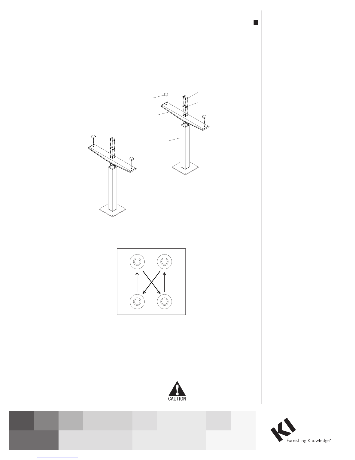
Note: When tightening the M8 screws, firsttwist
in all four screws“finger tight”.Then tighten the
screws one quarter turnattime usingadiagonal
tightening patternasshowninDetailA.Repeat
the diagonal pattern untilall four screwsare tight
(DetailA&Figure1).
Assemble Feet To Columns
1. Set the column on end with the smaller
(inner)square tube on the floor. The threaded
holes visible on the end of the column will be in
arectangular (not square) pattern(Figure1).
2. Place the foot over the column end so the
column fits into the square holein the foot. The
slotted holes in the foot should lineupwith the
four holes in the column end. If not the foot
needs to be removed and repositioned at 90
degrees (Figure1).
3. Attach the foot using four M8 x 20mm
screws and four 8mmflatwashers (Figure1).
4. Thread levelingglides into the holes at the
ends of the foot (Figure1).
5. Repeat steps 1 through4for the second
foot and column (Figure1).
WorkUp Fixed Height Tables
Model FX
WorkUp Fixed-Height Table
Model FX
November 2016
Figure 1
Detail A
leveling glide
foot
column
M8 x 20mm
screw
flat washer
Assemble units as described herein only. To do otherwise
may result in instability. All screws, nuts and bolts must be
tightened securely and must be checked periodically after
assembly. Failure to assemble properly, or to secure parts
may result in assembly failure and personal injury.
Tools Required
• #3 Phillips Screwdriver
• 5mm Hex Key
Note: Before discarding any
packaging confirm all components
received against the packing list.
Table assembly should be done on
a clean flat floor.
Note: When tightening the M8
screws, first twist all four screws
in “finger tight”. Then tighten the
screws one quarter turn at time
using a diagonal tightening pattern
as shown in Detail A. Repeat the
diagonal pattern until all four
screws are tight (Figure 1 &
Detail A).
Feet To Column Assembly
1. Set the column on end with the hole
pattern facing up (Figure 1).
2. Place the foot over the column
end so the column fits into the
square hole in the foot. The slotted
holes in the foot should line up
with the four holes in the column
end. If not the foot needs to be
removed and repositioned at 90
degrees (Figure 1).
3. Attach the foot using four
M8 x 20mm screws and four
8mm flat washers, tightening
each screw one quarter turn
at a time in a diagonal pattern
until all four screws are tight
(Figure 1 & Detail A).
4. Thread leveling glides into the holes
at the ends of the foot (Figure 1).
Note: If the roller foot option was
purchased, one foot will have
pre-assembled rollers.
5. Repeat steps 1 through 4 for the
second foot and column (Figure 1).
WorkUp Fixed-Height Table - Model FX
Assembly Instructions
Assemble units as described herein only. To do otherwise
may result in instability. All screws, nuts and bolts must be
tightened securely and must be checked periodically after
assembly. Failure to assemble properly, or to secure parts
may result in assembly failure and personal injury.
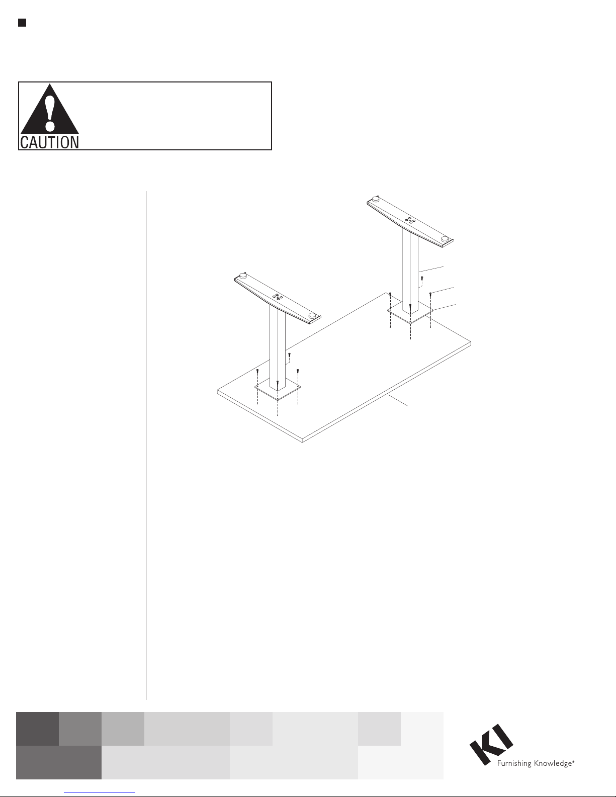
Worksurface Assembly
Note: The worksurface is
pre-drilled for installation of all
components.
1. To avoid scratching the
worksurface place it with the top
side down on a soft protective
material (Figure 2).
2. As illustrated, place the assembled
base over the pre-drilled holes on
the worksurface. Align the holes
in the worksurface with those
in the spider plate and attach to
the worksurface using #12 x 1”
tapping screws in each available
hole (Figure 2).
column
#12 x 1”
screw
spider plate
3. Carefully invert the table to its
upright position. Caution: The
table is very heavy. Two or more
people are required to turn the
table upright.
4. Adjust the leveling glides to level
the table.
Product Information
Maximum Load: The allowable
load is based on the size of the
worksurface and shall be evenly
distributed on the worksurface.
Allowable Load = Perimeter x 1.5 lbs.
Example: The allowable load for a
30” x 66” worksurface is
192 x 1.5 lbs. = 288 lbs.
worksurface
Figure 2
1330 Bellevue Street • P.O. Box 8100 • Green Bay, WI 54308-8100 • Tel 1-800-424-2432 • www.ki.com
© 2016 Krueger International, Inc. All Rights Reserved • Code KI-62447R3/KI/PDF/1116
 Loading...