

KI CR Assembly Instructions Manual
Assembly Instructions
WorkUp Adjustable Table
Model CR
November 2016
Tools Required
• #3 Phillips Screwdriver
• 5mm Hex Key
Note: Before discarding any packaging
confirm all components received
against the packing list. Table assembly
should be done on a clean flat floor.
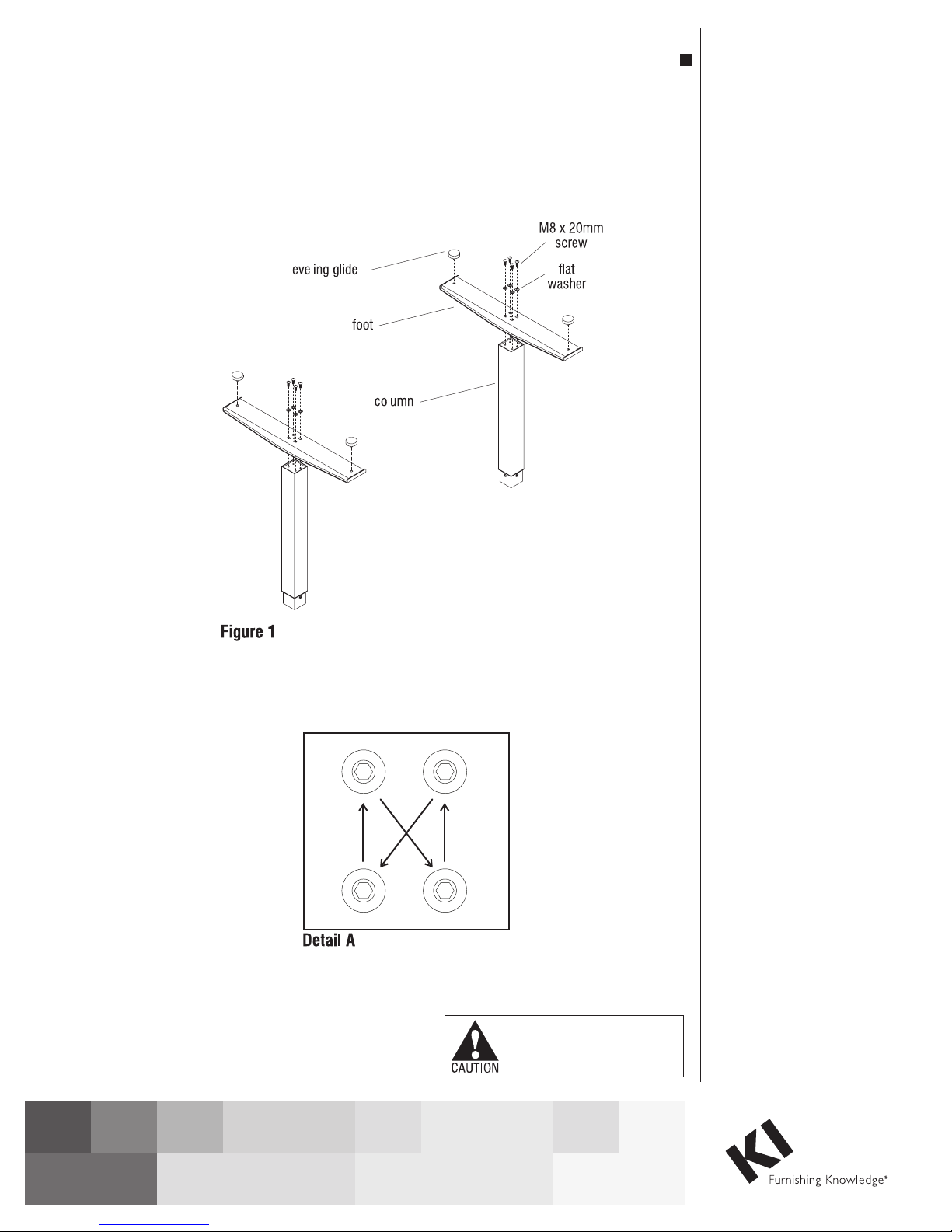
Note: When tightening the M8 screws,
first twist in all four screws “finger
tight”. Then tighten the screws one
quarter turn at a time using a diagonal
tightening pattern as shown in Detail A.
Repeat the diagonal pattern until all four
screws are tight (Detail A & Figure 1).
Assemble Feet To Columns
1. Set the column on end with the
smaller (inner) square tube on the
floor. The threaded holes visible
on the end of the column will be in
a rectangular (not square) pattern
(Figure 1).
Assemble units as described herein only. To do otherwise
may result in instability. All screws, nuts and bolts must be
tightened securely and must be checked periodically after
assembly. Failure to assemble properly, or to secure parts
may result in assembly failure and personal injury.
2. Place the foot over the column
end so the column fits into the
square hole in the foot. The slotted
holes in the foot should line up
with the four holes in the column
end. If not the foot needs to be
removed and repositioned at 90
degrees (Figure 1).
3. Attach the foot using four
M8 x 20mm screws and four
8mm flat washers, tightening
each screw one quarter turn
at a time in a diagonal pattern
until all four screws are tight
(Figure 1 & Detail A).
4. Thread leveling glides into the
holes at the ends of the foot
(Figure 1).
Note: If the roller foot option
was purchased, one foot will have
pre-assembled rollers.
5. Repeat steps 1 through 4 for the
second foot and column (Figure 1).
WorkUp Adjustable Table - Model CR
Assembly Instructions
Assemble units as described herein only. To do otherwise
may result in instability. All screws, nuts and bolts must be
tightened securely and must be checked periodically after
assembly. Failure to assemble properly, or to secure parts
may result in assembly failure and personal injury.
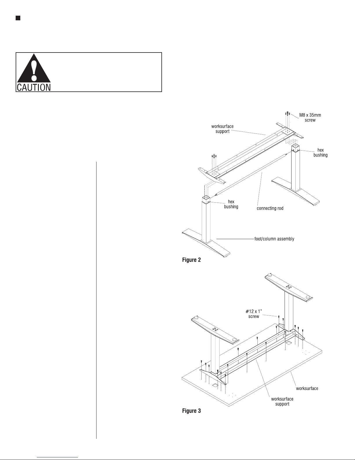
Assemble Columns To
Worksurface Support
1. With the foot/column assemblies
upright, place the connecting
rod into the hex shaped holes
on the inside of each column. At
this time be sure the other hex
bushing in each column is facing
the same direction. This direction
will become the front of the table.
If the two remaining hex bushings
are facing opposite directions,
rotate one foot/column assembly
so the two hex bushings are
facing the same direction
(Figure 2).
Note: Be careful not to rotate the hex
bushings on columns until the table
is assembled. Doing so will adjust the
columns to different heights.
2. Place the foot/column assembly
between the angle members of
the worksurface support and align
the four holes in one end of the
worksurface support with the four
holes in the column (Figure 2).
3. Attach the worksurface support
using four M8 x 35mm screws,
tightening each screw one quarter
turn at a time in a diagonal pattern
until all four screws are tight
(Figure 2 & Detail A).
4. Attach the second foot/column in
the same manner (Figure 2).
Assemble Worksurface
Note: The worksurface is pre-drilled
for installation of all components.
1. To avoid scratching the
worksurface place it with the top
side down on a soft protective
material.
2. Place the worksurface support
with columns on the drilled face
of the worksurface so the heads of
the M8 bolts set into the pockets
milled in the worksurface. The
worksurface support should now
be flush with the worksurface
(Figure 3).
3. Move the worksurface support
with columns slightly to align
the holes in the worksurface with
those in the worksurface support
(Figure 3).
4. Attach the worksurface using
#12 x 1” tapping screws in each
available hole (Figure 3).
2
 Loading...