

KI CB Assembly Instructions Manual
Assembly Instructions
WorkUp® Adjustable Table
Model CB
August 2017
Frame Assembling
WARNING: The columns of this table
base contain high force springs that
are sized to lift the worksurface
and accessories. If the release
lever is activated when the table is
inverted, or before the worksurface
is installed, the lack of weight on
the columns will allow the columns
to extend suddenly with great force.
Sudden extension will damage
the table and could cause serious
injury.
DO NOT REMOVE SAFETY PIN
(RING) OR WARNING TAG UNTIL
TABLE IS COMPLETELY ASSEMBLED
AND IN THE UPRIGHT POSITION.
Tools Required:
• #2 Phillips Screwdriver
• #3 Phillips Screwdriver
• 5mm Hex Key
• 6mm Hex Key
Note: Before discarding any packaging,
confirm all components received against
the packing list.
Assemble units as described herein only. To do otherwise
may result in instability. All screws, nuts and bolts must be
tightened securely and must be checked periodically after
assembly. Failure to assemble properly, or to secure parts
may result in assembly failure and personal injury.
Note: Assembly should be done on a
clean, flat, and soft, surface.
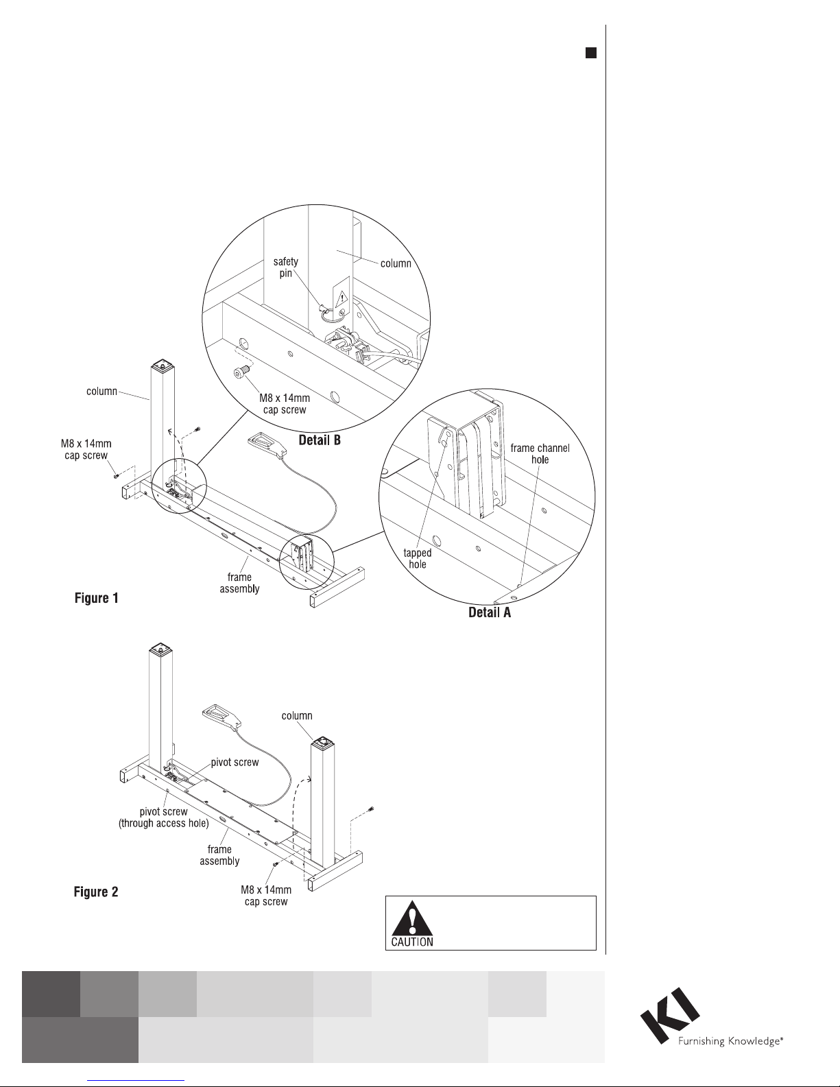
1. Position the folded frame assembly as
illustrated, onto a clean soft surface.
Rotate the top-most of the two columns up
vertically until the two tapped holes in the
column align with the frame channel holes
(Figure 1 & Detail B).
2. Loosely insert two M8 x 14mm screws
from the outside, at each side of the frame
support bracket, through the frame channel
holes and into the inner tapped holes.
Do not tighten at this time
(Figure 1 & Detail B).
Note: See Detail A of the lower-folded
column to identify the tapped hole of the
column, and the frame channel holes
which are similar for the “top-most”
column of Detail B.
3. Locate the two pivot screws, one on each
side of the frame assembly. Using a
6mm Hex Key, tighten both pivot screws,
then tighten each of the four installed
screws from step 2 above. Tighten all
screws to 7 ft/lbs (Figure 2).
4. Repeat the steps above for the second
column (Figures 1 & 2, Details A & B).
WorkUp® Adjustable Table - Model CB
Assembly Instructions
Assemble units as described herein only. To do otherwise
may result in instability. All screws, nuts and bolts must be
tightened securely and must be checked periodically after
assembly. Failure to assemble properly, or to secure parts
may result in assembly failure and personal injury.
Note: When tightening the M8
screws into the top of the column,
start by twisting in all four screws
“finger tight”. Then tighten the
screws one quarter turn at a time
using a diagonal tightening pattern
as shown in Detail B. Repeat the
diagonal pattern until all four screws
are tight.
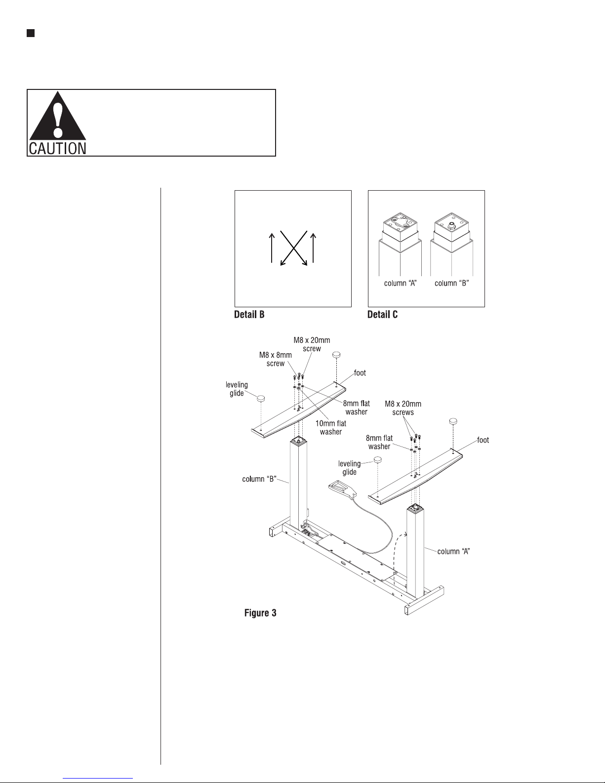
Note: Refer to Detail C to identify
columns “A” and “B”.
Foot to Base Assembly,
Column “A”
1. With the base inverted, place a foot
over the end of column “A” so the
column fits into the square hole in
the foot. The holes in the foot should
line up with the four holes in the
column end. The short threaded rod
that protrudes from the column end
should also line up with a hole in
the foot. If not the foot needs to be
removed and repositioned (Figure 3
& Detail C).
2. Attach the foot using four
M8 x 20mm screws and four 8mm
flat washers (Figure 3).
Note: If the roller foot option was
purchased, one foot will have
pre-assembled rollers.
3. Thread a leveling glide into the holes
at the ends of the foot (Figure 3).
Foot to Base Assembly,
Column “B”
1. Place a foot over the end of column
“B” so the column fits into the square
hole in the foot. The holes in the foot
should line up with the three holes
and special nut in the column end.
If not, the foot needs to be removed
and repositioned (Figure 3 &
Detail B).
2. Attach the foot using three
M8 x 20mm screws with three 8mm
flat washers, and one M8 x 8mm
screw with one 10mm flat washer
(Figure 3).
3. Thread a leveling glide into the holes
at the ends of the foot (Figure 3).
2
 Loading...