

KI 700 Series Assembly Instructions Manual
August 1997
Assembly Instructions
KI 700 Series Desk Corner Unit
KI Pembroke
P.O. Box 580
1000 Olympic Drive
Pembroke, Ontario
K8A 6X7
TEL (613) 735-5566
FAX (613) 735-3333
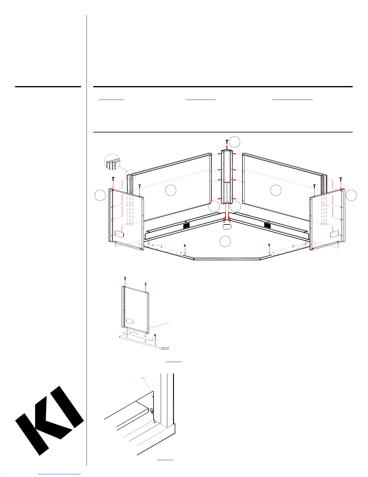
Components
1 - Worksurface
2 - End Panel
3 - Modesty Panel
4 - Corner Column
5 - Wire Management Channel
2 2
Tools Required
Ÿ Phillips Screwdriver
Ÿ 3/8” Socket/Wrench
4
3 3
55
1
Hardware Parts List
(24)#20162 - #8 x 1/2” Screws
(6) #20192 - #14 x 7/8” Screws
(8) #20203 - 10-16 x 1/2” Self Drilling
(5) #20425 - Hex Glides
1. To avoid scratching worksurface,
Screws
place face down on a protective
surface.
End
Panel
Level Connector
Wire Management
Channel
Worksurface
#14 x 7/8”
Screw
Detail A
Detail B
2. If attaching bridge/return, align level
connector (shipped with bridge/
return) with holes in worksurface.
Place end panel on level connector
and secure in place with (3)
#14 x 7/8” screws (Detail A).
Repeat for opposite end.
3. Using (2) #14 x 7/8” screws attach
corner column to underside of top.
4. Position modesty panel between end
panel and corner panel. Note: Double
flanged end of modesty panel
attaches to end panel. Aligning
holes use (6-8)* #8 x 1/2” screws to
attach modesty panel to corner
column and end panel. Repeat for
next modesty panel.
5. Place wire management channel on
worksurface, product label facing
inward, align holes with predrilled
holes in worksurface. Secure in
place using (3) #8 x 1/2” screws
(Detail B). Repeat for next wire
management channel.
* (6) - #8 x 1/2” screws partial
modesty panel
(8) - #8 x 1/2” screws full modesty
panel
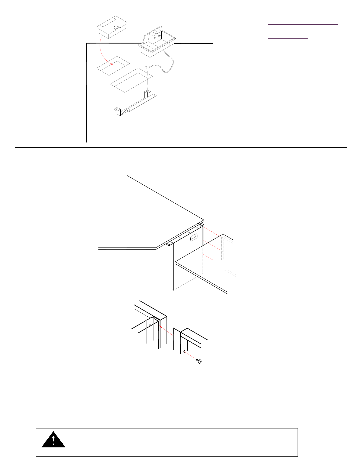
Grommet
Shield
PowerUp
Worksurface
Installing Grommets & PowerUp
Hardware Parts List
(4)#20162 - #8 x 1/2” Screws
1. Press worksurface grommets into
wireway holes in worksurface.
PowerUp Only
2. Route cord through the hole in the
worksurface. Snap the PowerUp option into the hole in worksurface.
3. Install PowerUp shield to underside of
worksurface using (4) #8 x 1/2”
screws.
Attaching Bridge/Return to Corner
Unit
1. Slide Bridge/Return modesty panel
flange between corner unit end panel
and modesty panel. Fasten with
(3-4)* self drilling screws (Detail B).
Note: There are no pilot holes in the
corner unit modesty panel.
Desk Corner Unit
Corner Unit
Modesty Panel
Bridge/Return
Bridge/Return
Modesty Panel
Self Drilling
Screw
Detail B
2. Place Bridge/Return on level
connector previously attached to
corner unit. Use (2) #14 x 7/8”
screws to attach.
3. Level Bridge/Return by adjusting hex
glides.
* (3) - 10-16 x 1/2” Self Drilling
Screws for partial modesty panel
(4) - 10-16 x 1/2” Self Drilling
Screws for full modesty panel
Assemble units as described herein only. To do otherwise may result in instability. All screws, nuts and
bolts must be tightened securely and must be checked periodically after assembly. Failure to assemble
properly, or to secure parts may result in assembly failure and injury.
CAUTION
21182-2 Jan. 1998
 Loading...