

KFE KF-COE-208, KF-COE-240 Installation And Operation Manual
Installation and Operation Manual
ELECTRIC CONVECTION OVEN
Model: KF-COE-208
KF-COE-240
Please read this manual completely before attempting
to install, operate or service this equipment
Installation and Operation of Electric Convection Oven
IMPORTANT WARNING AND SAFETY INFORMATION
FOR YOUR SAFETY:
Do not store or use gasoline or other flammable vapors or liquids
in the vicinity of this or any other appliance.
: Improper installation, adjustment, alteration, service or
maintenance can cause property damage, injury or death. Read the
installation, operating and maintenance instructions thoroughly before
installing or servicing this equipment.
THIS MANUAL MUST BE RETAINED FOR FUTURE REFERENCE.
SPECIFICATIONS
TOTAL KW
VOLTAGE
1 PHASE
3 PHASE
10KW
208V
240V
53 A
31 A
10KW
46 A
27 A

Installation and Operation of Electric Convection Oven
INSTALLATION INSTRUCTIONS
A. QUALIFIED PERSONNEL
The oven should be placed in an area that is free
from drafts and accessible for proper operation
and servicing.
These installation instructions are for the use of qualified
installation and service personnel only. Installation or
service by other than qualified personnel may result in
damage to the oven and/or injury to the operator.
Refer to the Oven Placement Clearances Chart
before installing the oven.
Qualified installation personnel are those individuals,
firms,companies or corporations which either in personor
throughan agent is engaged in and responsible for:
OVEN PLACEMENT CLEARANCES CHART
COMBUSTIBLE
NON-COMBUSTIBLE
Right Side
Left Side
Rear
1"
1"
3"
8"
0"
0"
3"
8"
•
The installation of electrical wiring from the electric
meter, main control box or service outlet to the
electrical appliance.Qualified installation personnel
must be familiar withall precautions required and
have complied with all requirements of state and
local authorities having jurisdiction. See: National
Electrical Code, ANSI/NFPA70.
Floor
It is also important not to obstruct the natural flow of
ventilation air if the oven is to operate properly. This
oven should not be installed on a curb base or sealed
to the wall. Either condition can restrict the flow of air to
or prevent proper ventilation of the blower motor. The
blower motor has a thermal protection device,which will
trip, because of excessive ambient temperatures at the
back of the oven. This condition should be corrected
immediately to avoid damaging the oven permanently.
B. DELIVERY AND INSPECTION
KFEdoes everything with in its power
to insure you received your oven in good condition.
They are strapped down on heavy wooden skids and
Surrounded by heavy “tri-wall” carton stop revent shipping
damage. They have all been carefully inspected before
they were packaged and consigned to the carrier.
Before making any connections to the oven, check the
specification plate to be sure the oven specifications
concur with the voltage and phase to be supplied to
the oven.
Upon delivery of your KFEoven:
Look over the shipping container,carefully noting any
Exterior damage on the delivery receipt, which must
also be signed by the driver/ delivery person.
The specification plate islocated behind the lower front
panel.To access the specification plate,loosen the four
screws below the doors, and pull the panel outward.
Uncrate and check for any damage, which was not
evident on the outside of the shipping container.
This is called concealed damage.The carrier must
be notified within fifteen (15) days of the delivery
of the oven and the carton, skid and all packaging
materials must be retained for inspection.
Thespecificationplatebearingtheoven’sserialnumber
is attached to the underside of the upper ledge above
the control panel.
D. ELECTRICAL CONNECTIONS
KFE cannot assume liability for
Loss or damage suffered in transit. The carrier assumes
full responsibility for delivery in good order when the
shipment was accepted. However, we are prepared to
assist you in filing your claim.
The oven is supplied for connection to a 208, 240, 440
or 480 volt grounded circuit. The electric motor, oven
lights,indicatorlightsandcontrolcircuitsareconnected
internally and require no secondary power supply.
Before making any connections to these units, check
the specification plate to assure that the voltage and
phase of the oven is compatible with the electrical
supply. When installing, all ovens must be electrically
grounded in accordance with local codes or in the
absence of local codes, with the National Electrical
Code, ANSI/NFPA 70 (in Canada – CSA Std. C22.1).
Wiring diagrams are located in the control compartment
C. LOCATION OF THE OVEN
Proper planning and placement of the oven will give you
the best results in terms of long-term user convenience
and satisfactory performance. We urge you to give
adequate thought in the placement of your oven prior
to its arrival.
Installation and Operation of Electric Convection Oven
area. Standard wiring schematics are also included at
the back of this manual.
NOTE: If you plan to use casters, a fixed restraint of the
Proper length must be incorporated to secure the oven to
a non-movable surface to eliminate strain on the power
cord.If the oven is removed from its normal position,the
restraint must then be reattached when returned.
Note to Electrical Inspector: Inspection of
electrical connection should be accomplished by the
removal of the lower finishing piece. This is done by
loosening the four screws located in the door opening
under the doors.
Double Sections
Secure the short legs to the bottom of the lower
section as described in previous section.
E. OVEN ASSEMBLY
Casters are installed by the method described for
single section ovens in the previous section.
Before assembling and installing the oven, please
check to make sure that all necessary parts are
present. In addition to the oven itself, there will also
be four legs, four feet or four casters, the vent guard,
(for double sections: retaining clips & vent riser) and
miscellaneous hardware. Please check the interior of
all oven sections for the parts needed to assemble and
install the oven(s).
Place upper section on top of lower section and
align all edges of the ovens.
Locate securing clips and align withholes on rear
frames of oven section, install three screws each
as provided and tighten.
At the rear of the oven, install the flue connector
by sliding it up through the flue vent opening in
the top of the oven and over the upper flue vent.
Push it flush with the back of the oven then slide it
down over the lower flue vent. Attach with screws
provided.
Leg Attachment
•
•
•
Once the oven has been removed from the
carton, lay it on its left side (the side without the
controls).
hold the leg and align with the threaded hole in the
front corner of the bottom of the oven.Carefully start
the bolt in the corner (avoid cross threading).
Install flue guard or draft hood adapter and draft
hood and draft hood collar to upper section.
Align the other two leg plate holes in the leg with
Those in the oven bottom and secure each leg using
the remaining two leg bolts. Repeat this process
for all legs.
F. ADJUSTMENTS ASSOCIATED WITH
INSTALLATION
Each oven section and all its component parts have
been tested thoroughly and inspected before the oven
wasshippedfromthefactory.However,itissometimes
necessary to further test or adjust the oven once it has
been installed.Such adjustments are the responsibility
of the Dealer or Installer. These types of adjustments
are not considered defects,rather anormal and routine
part of the proper installation of the equipment.
•
•
Raise the oven up on the legs.
Level the oven by turning the adjustable feet in or
out as needed.
Caster Installation
•
Casters are available as an option for both the
single and double oven sections.
These adjustments include but are not limited to:
•
The installation of casters requires the removal of
the adjustable feet from the legs. This is done by
placing the bit of a large screwdriver against the lip
of the foot and rapping the screwdriver to drive the
foot out of the leg. The caster is then inserted fully
into the opening where the foot came out and the
locking nut tightened to expand the compression
sleeve of the caster.
•
•
•
•
Adjustments and recalibration of the thermostat
Adjustment to the doors.
Leveling.
Tightening of fasteners.
No
installation should be
NOTE:The casters with locking brakes are best mounted
on the front side of the oven for easier access.
considered complete without proper inspection
and, if necessary, any adjustments by qualified
service or installation personnel.
Installation and Operation of Electric Convection Oven
OPERATING INSTRUCTIONS
The information in this section is intended for the use
THE COE SERIES OF CONVECTION
OVENS
of qualified operating personnel. Qualified Operating
Personnel are those individuals who have carefully
read the information contained in this manual, are
familiar withthe function of the oven and/or have had
experience with operating the equipment described.
We recommend following these instructions to insure
Optimum performance,long life and trouble-free service
from your oven.
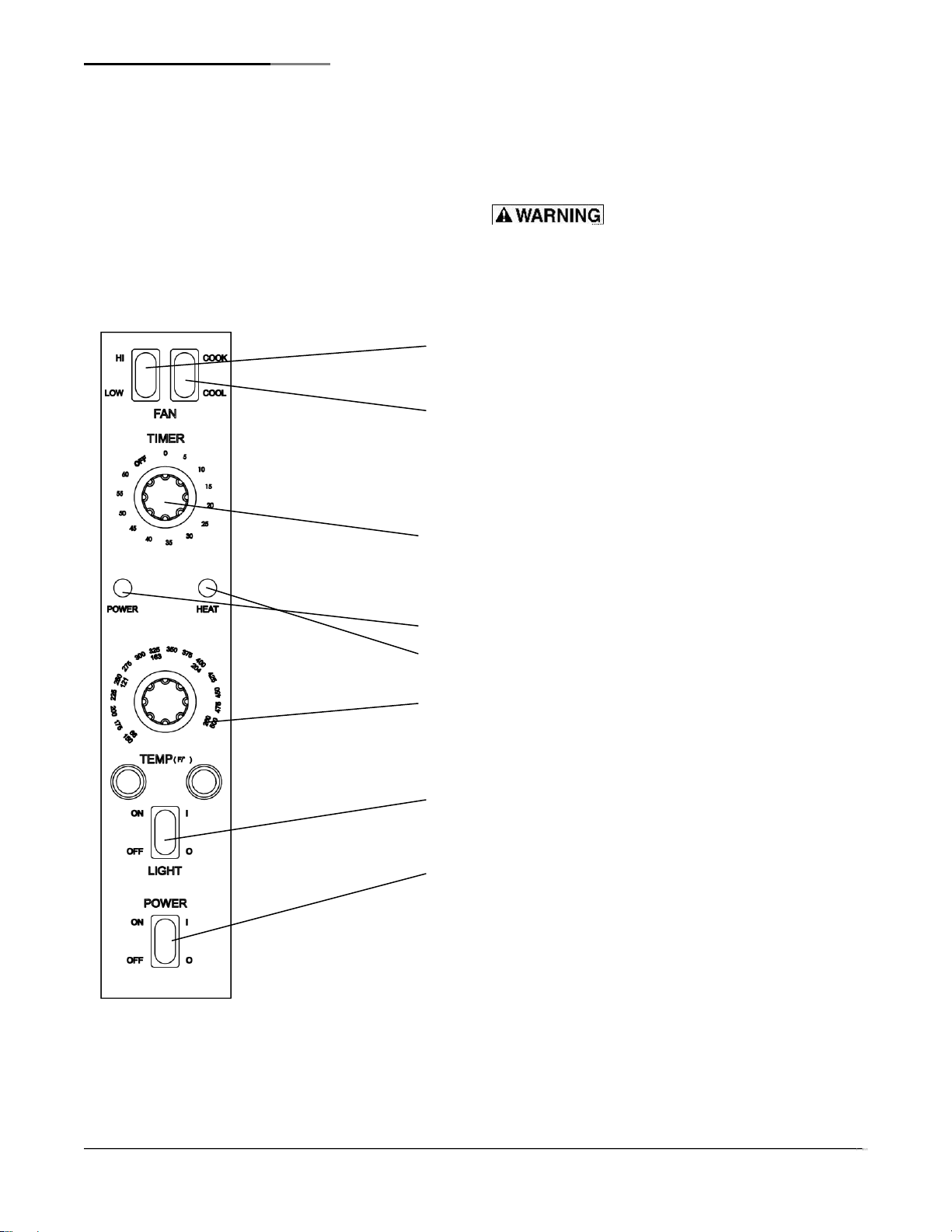
1. Fan speed
Use to select fan spped,HI or LOW, The appropriate speed is determined
by the type of food being cooked.
2. Fan Mode
In COOK mode,the fan runs continuously except when the doors are
open,The fan does NOT cycle with iperation of burners. In COOL mode,
the fan runs continuously even if the doors are open. Since the burners will
not operate if the oven doors are open, to repidly cool the oven after
cooking is completed, open the doors and switch the fan mode to COOL.
3. Cook Timer
Turn knob to set a time duration. An alarm will sound when the timer runs
out,The timer is reminder to the user; the timer dones not control the
oven.
4. Power on Light
5. Heat-On indicator
Do not attempt to operate oven during a power failure.
Do not attempt to operate oven during a power failure.
6. Cook Temperature Control
Turn knob to select desired cooking temperature, The heat on
indicator will go out when the oven reaches the set temperature,and
wil cycle on and off as the burners operate to maintain the set cooking
temperature.
7. Oven Interior Light Switch
On ovens equipped with an oven interior light,press to turn on the light.
The light remains on for as long as the switch is held.
8. Power Switch
Switch ON to use the oven, switch OFF when done using the oven.
f
 Loading...