

Keywish Hummer-Bot Instruction Manual
Hummer-Bot Instruction
Manual
Github https://github.com/keywish/keywish-hummer-bot

1
Data
Versio
n
Description
Author
2017/9/16
V-1.0
Create
Baron.li
2017/9/23
V-1.1
modify
Ken.chen
2017/10/18
V-1.2
Review
Ken.chen
2017/11/15
V-1.3
Review
Zach.zhou
2017/12/8
V-1.4
Review
Baron.li
2018/3/11
V-1.5
Modify ir/blutooth module
Ken.chen
2018/4/20
V-1.6
Add device instructions
Baron.li
2018/5/3
V-1.7
Add installation details picture
Baron.li

2
table of Contents
Chapter1 Introduction ......................................................................... 1
1.1 Writing Purpose ...................................................................... 1
1.2 Product Introduction ............................................................... 2
Chapter2 Preparations ......................................................................... 8
2.1 About Arduino ........................................................................ 8
2.2 Why Choosing Arduino .......................................................... 8
Chapter3 Experiments ....................................................................... 11
3.1 Assembly of the Car ............................................................. 11
3.1.1 Bottom Mounting of the Car ....................................... 11
3.1.2 Surface Mounting of the Car ...................................... 28
3.2 Development of the Car ....................................................... 42
3.2.1 Walking Principle of the Car ...................................... 42
3.2.2 Infrared Obstacle Avoidance ...................................... 49
3.2.3 Infrared Tracing .......................................................... 57
3.2.4 Ultrasonic Obstacle Avoidance .................................. 65
3.2.5 Infrared Remote Control ............................................. 79
3.2.6 PS2 Handle (Optional) ................................................ 86
3.2.7 Mobile Phone Bluetooth Control ................................ 97

1
Chapter1 Introduction
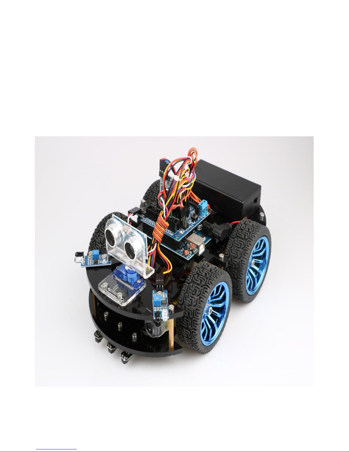
"Hummer-Bot" is a multi-function car based on Arduino UNO R3, which is composed of embedded
micro-controller, sensor, mechanical movement, wireless communication module and other parts. Although
it cannot sing and dance like the traditional robot, it is also very intelligent and a member of the family of
intelligent robot. By virtue of the inherent talent, Hummer-Bot can run on every corner, automatically avoid
obstacles and walk along the black and white lines freely, of course, people can also play it via such as
Bluetooth, infrared ray, PS2 remote sensing control, with passion and all kinds of attitude.
In the robot-prevalent era, sensor, wireless and power technologies are indispensable parts of people's
lives, such as infrared is widely used in industrial robot, ultrasonic wave is widely applied in the medical
industry, as to the wireless technology, it is beyond count. WIFI, Bluetooth, infrared, and ZigBee are
becoming irreplaceable parts in smart Home Furnishing. "Hummer-Bot" is a very product of the
development of the robot by combing these technologies perfectly, it can be used conveniently, developed
easily. In addition, "Hummer-Bot" has a variety of modes, can be switched freely and completed a variety of
development on one platform, which is the best choice for every electronic enthusiasts.
"Hummer-Bot" is a car which combines machine and electric, people can feel like in a competition
through wireless control, this is not only a test of endurance and confidence for enthusiasts, but also a
training to their response. The core of the car’ walking is motor control, a good motor and drive are the
necessary conditions for the car’ journey to success, "Hummer-Bot" contains 4 DC motors and a high power
drive chip, which enable the driving force of the car to a higher level.
The key to judgment depends on the sensor, just like the five senses of human beings, which is always
aware of everything around it, and avoids unnecessary mistakes, such as collision, migration and so on. The
combination of power and sensor makes the car more flexible and data acquisition more accurate.
1.1 Writing Purpose
The purpose of this manual is to create a fast, practical and convenient development learning platform
for the vast number of electronic enthusiasts and let them grasp the Arduino and its extended system design
methods and design principles, as well as the corresponding hardware debugging methods.
This manual will lead you to learn every function of "Hummer-Bot" step by step and open a new
"Hummer-Bot" journey for you. It is divided into two parts: 1, Preparation chapter, which mainly introduces
the use of common Arduino development software and some downloading and debugging skills. 2,
Experiment chapter, which contains hardware and software, the former mainly introduces the function and
principle of each module; the latter mainly introduces each part of the program and leads you to understand
and grasp the principle of Arduino and the car development through written examples step by step.

2
This manual is a specifications for "Hummer-Bot" , the file whose format is PDF which is in the CD
along with our product requires the corresponding software to open. It contains detailed schematic diagrams
and complete source codes for all instances, the codes won't have any mistake under our strict test. In
addition, the library files used in the source codes are put into the corresponding path, you only need to see
corresponding phenomenon of the car and personally experience the process of experiment by downloading
the source codes to Arduino via the serial port emulator.
This manual is not only very suitable for students and electronic enthusiasts, but also a good reference
for companies to develop products.
1.2 Product Introduction
"Hummer-Bot" is a multifunctional car based on the Arduino UNO and L298N motor. Compared with
the traditional car, "Hummer-Bot" is also equipped with wireless control (Bluetooth, infrared, WIFI and so
on); ultrasonic; infrared. It can trace and avoid obstacles automatically, of course, makers can also
automatically control the car with wireless and make full use of each module, as well as integrate all kinds
of related sensors to make the car more intelligent, which is more challenging. "Hummer-Bot" has various
types of information, technical manuals, routines, etc., which can teach you step by step. Each electronic fan
can use it easily to achieve their desired function.
Product Features
◆ Three groups of black line infrared tracing module
◆ Two group of infrared obstacle avoidance module
◆ Ultrasonic obstacle avoidance
◆ Four DC motor drive
◆ Two 3000mZh, 3.7V rechargeable lithium battery with longer endurance
◆ Remaining capacity of battery real-time detection
◆ Infrared remote control
◆ Bluetooth app control
◆ PS2 handle control (optional)
3
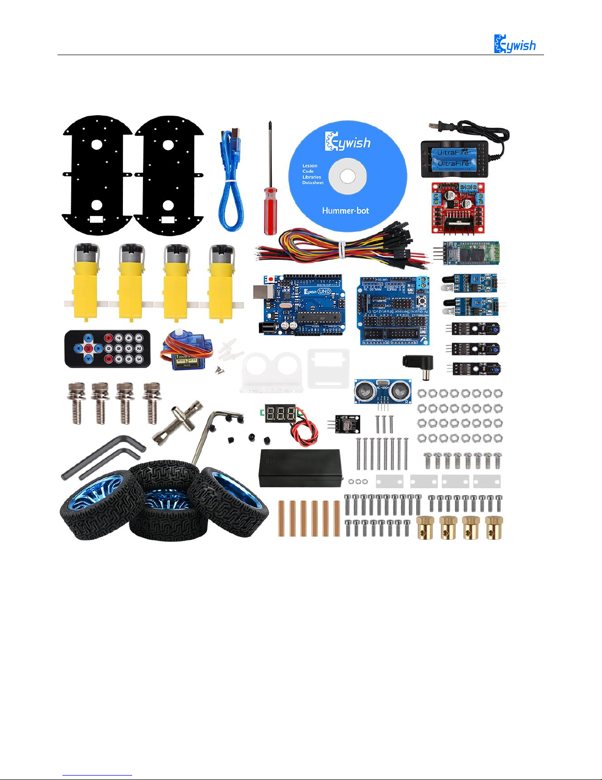
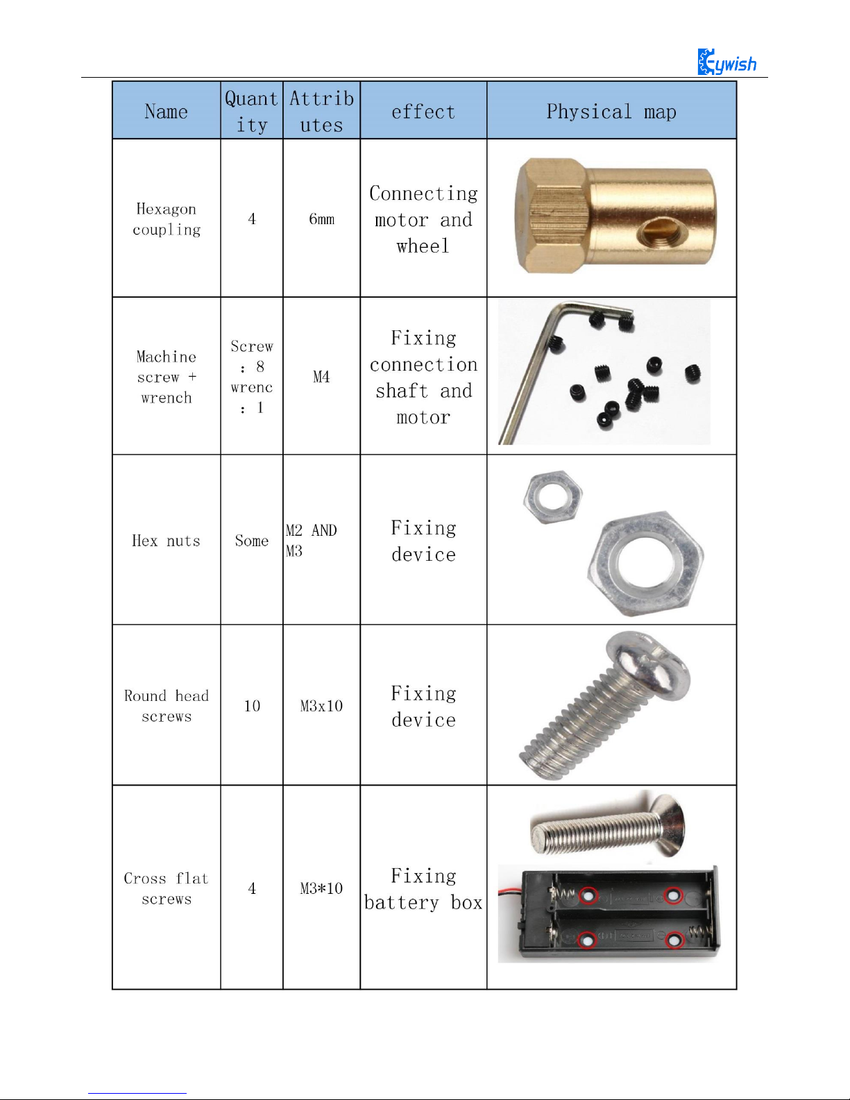
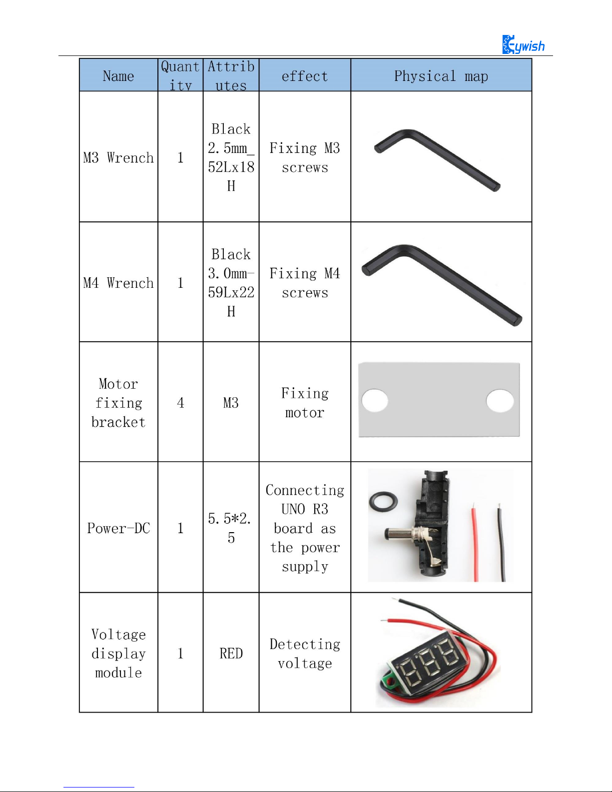
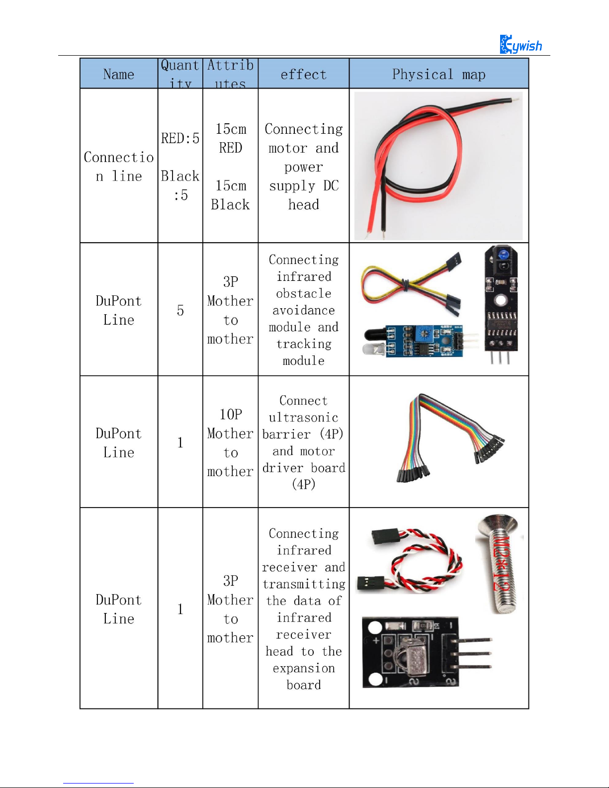
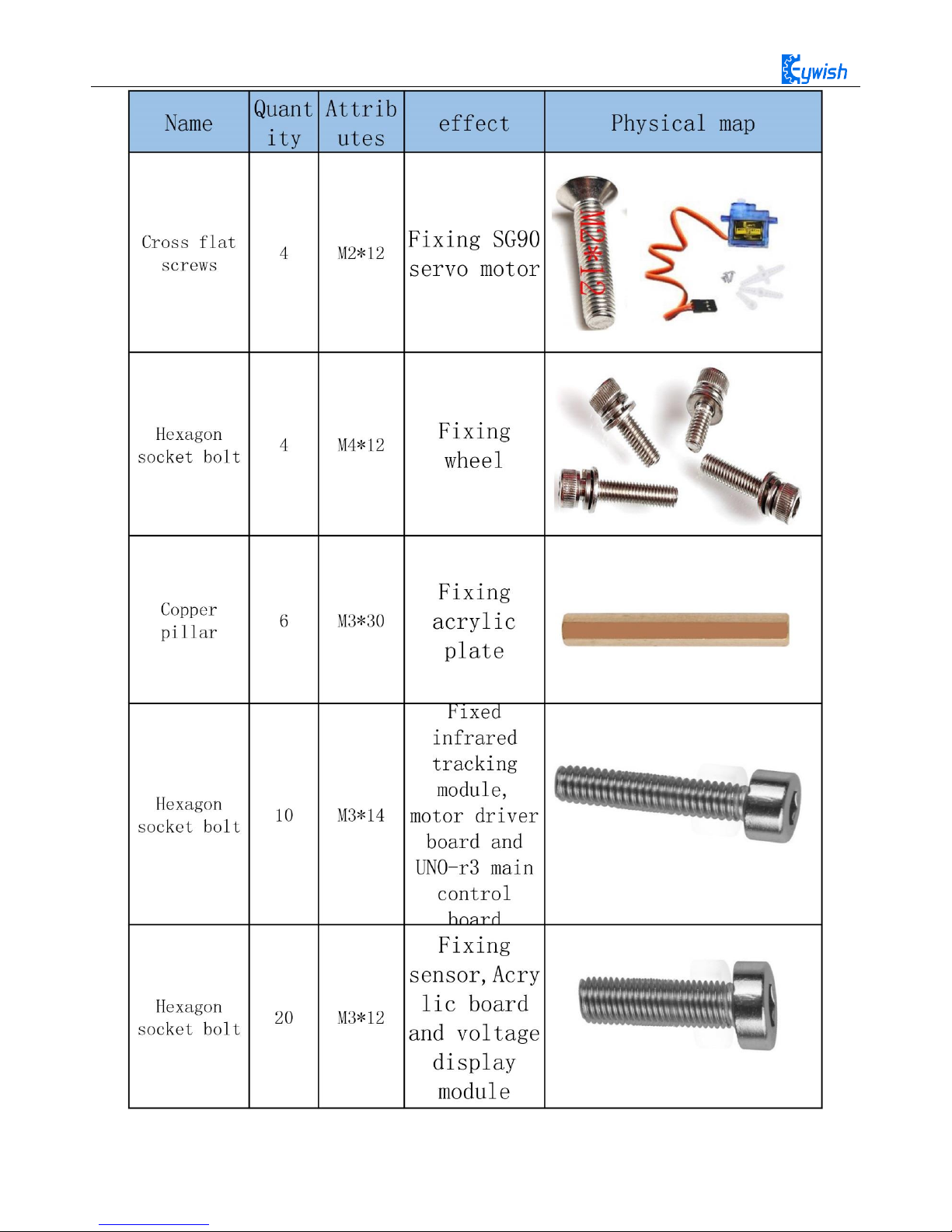
Product component invento
Note:
Please refer to the following table for instructions for use of
each accessory device:
4
5
6
7

8
Chapter2 Preparations
2.1 About Arduino
At the beginning of the study, let us read this little story: In the north of Italy, there is a picturesque
town which across the blue green Dora Baltea River whose name is Ivrea, it is a place full of colorful history
for it is where the king was born. In AD 1002, King Arduino became the ruler of the state, unfortunately two
years later he was deposed by the German King Henry II and became an oppressed king. Today, in a street
called cobblestone, there is a bar named di Re Arduino to commemorates the king appears in people's lives.
The bar owner Massimo Banzi (there is a saying: Massimo Banzi often comes to this bar) is an electronics
engineer in Italy, and later he named the electronic product Arduino in memory of this place. Arduino is a
convenient, flexible, open source electronic prototype platform, including hardware (various types of
Arduino board) and software (Arduino IDE). It is suitable for artists, designers, electronic lovers.
Arduino can perceive the environment through a variety of sensors, feedback, and influence the
environment by controlling lights, motors, and other devices. The microcontroller on the board can write
programs through Arduino programming language, compiled into binary files, burned into microcontroller.
The programming of Arduino is realized by Arduino programming language (based on Wiring) and Arduino
development environment (Based on Processing). Projects based on Arduino can either only contain
Arduino or contain Arduino and some other software on the PC, they can communicate via such as Flash,
Processing, MaxMSP.
You can do it yourself, or you can buy a finished kit, the software that Arduino uses can be downloaded
for free. The hardware reference design (CAD file) also follows the available open-source protocol, and you
can be very free to modify them according to your own requirements.
Arduino can not only use electronic components such as Switch or sensors or other controllers, LED,
stepping motors or other output devices that are developed, but also operate independently as an interface
that communicates with software, such as flash, processing, Max/MSP, VVVV, or other interactive
software.
In addition, Arduino is based on the AVR platform and does second compilation and packaging for
AVR library, the port is packaged, so you basically do not need to manage the register, address pointer and
so on, the difficulty of software development is greatly reduced, it is suitable for non professional
enthusiasts. Advantages and disadvantages coexist due to the second compilation and packaging, the code is
not conciser than original AVR code, and code execution efficiency and code volume is weaker than AVR
direct compilation.
2.2 Why Choosing Arduino
There are many SCM and SCM platform suitable for interactive system design. For example: Parallax
Basic Stamp, Netmedia 's BX-24, Phidgets, MIT' s Handyboard, and so on. All of these tools, you do not
need to care about the cumbersome details of SCM programming, they provide you with a set of easy-to-use

9
kit. Arduino also simplifies the working process of the microcontroller, but compared with other systems,
Arduino is more advantageous in many places, especially for teachers, students and some amateurs:
1, Cheap - compared with other platforms, the Arduino board is pretty cheap. The cheapest version of
Arduino can be made by hand, even if it's finished, the price will not exceed 200 yuan.
2, Cross platform - Arduino IDE can run in Windows, Macintosh, OSX, and Linux operating system.
Most other SCM software can only run on Windows.
3, Simple programming environment - beginners can easily learn to use the Arduino programming
environment, but it can also provide enough advanced applications for advanced users. As for the teachers,
the Processing programming environment can be used easily, so if students have learned how to use
Processing programming environment, then they will feel familiar when using the Arduino development
environment.
4, Open source software and extensible - Arduino software is open source, experienced programmers
can extend it. Arduino programming language can be extended through the C++ library, if someone wants to
understand the technical details, you can skip the Arduino language and use AVR C programming language
(because Arduino language is actually based on AVR C). Similarly, you can add AVR C code directly to
your Arduino program if necessary.
5, Open source hardware can be extended - Arduino is based on the ATMEGA8 and ATMEGA168/328
MCU of Atmel, it is also based on the Creative Commons license agreement, so experienced circuit
designers can design their own modules by extension or improvement according to their own requirements.
Even for some relatively less experienced users, they can also make a test board to understand how Arduino
works, which is money-saving and time-saving .
10
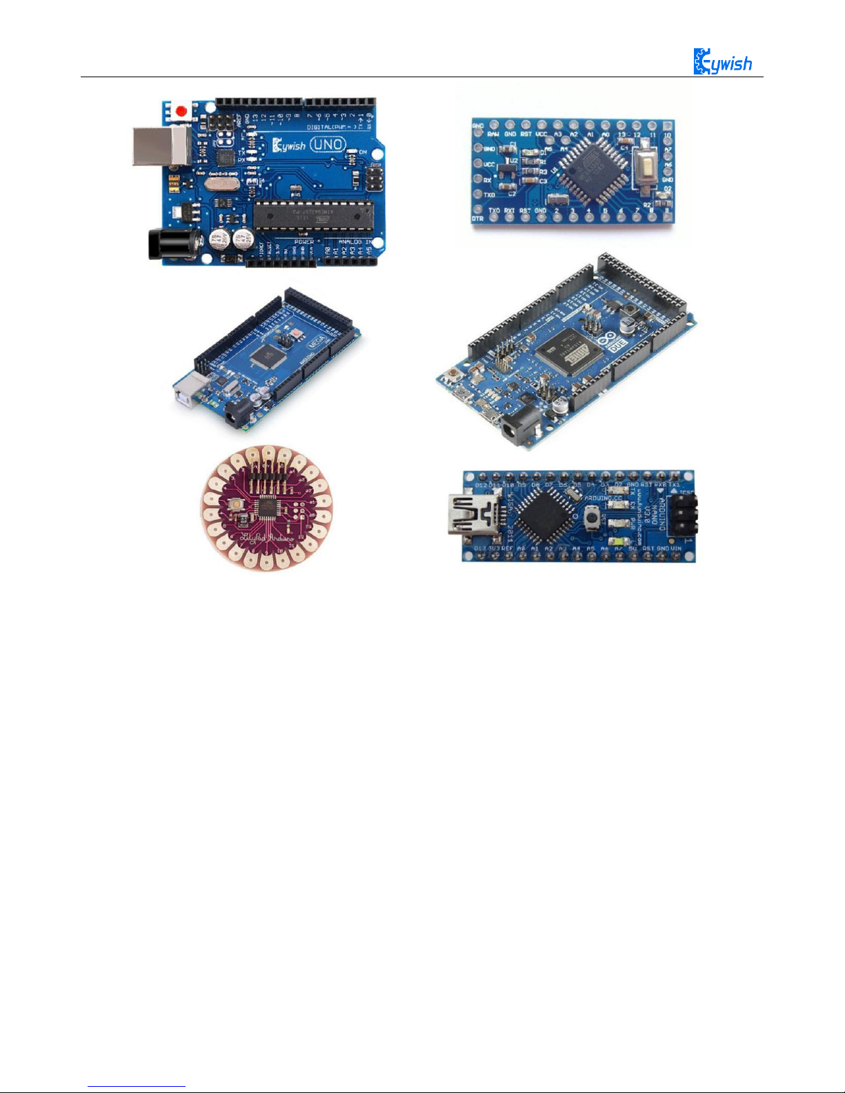
Fig 2.2 Several commonly usedArduino
11
Chapter3 Experiments
3.1 Assembly of the Car
3.1.1 Bottom Mounting of the Car
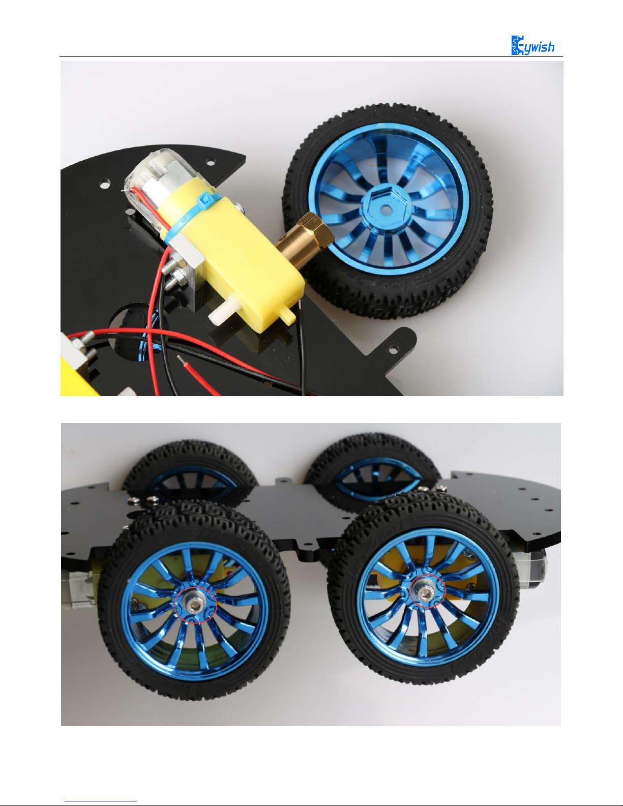
First we open the box, take out the car body (two black acrylic), screwdriver, M4x12 screws, six angle
coupling and matching set screws, four black&red welding wires and four motor and wheels.
The first step is to Mounting motor mount.

12
After the completion as shown.
13
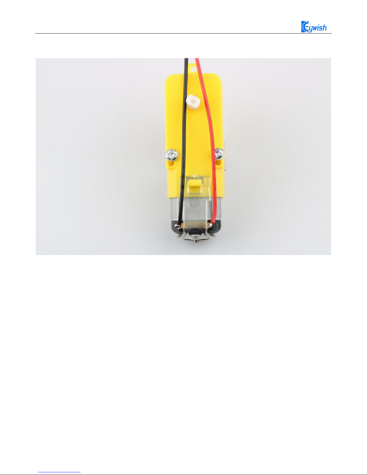
The second step is to Welding wire on the motor.
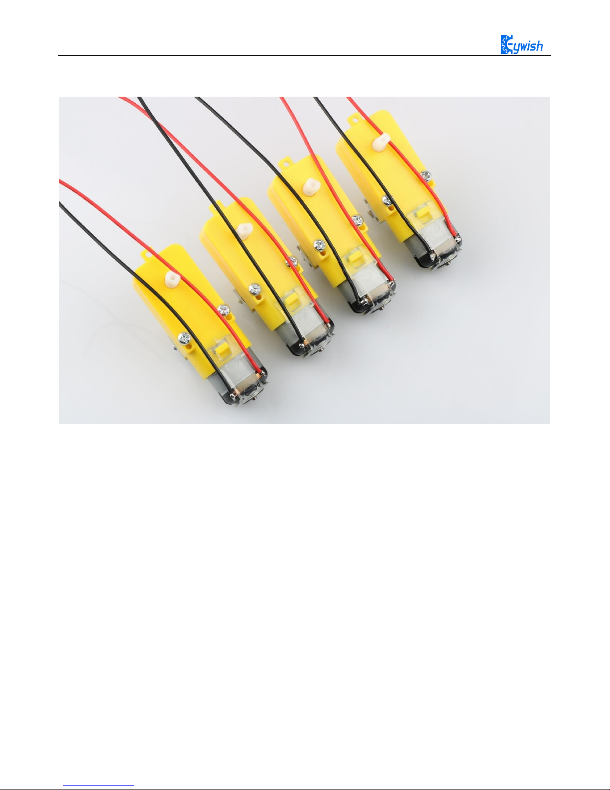
14
After the completion as shown.
15
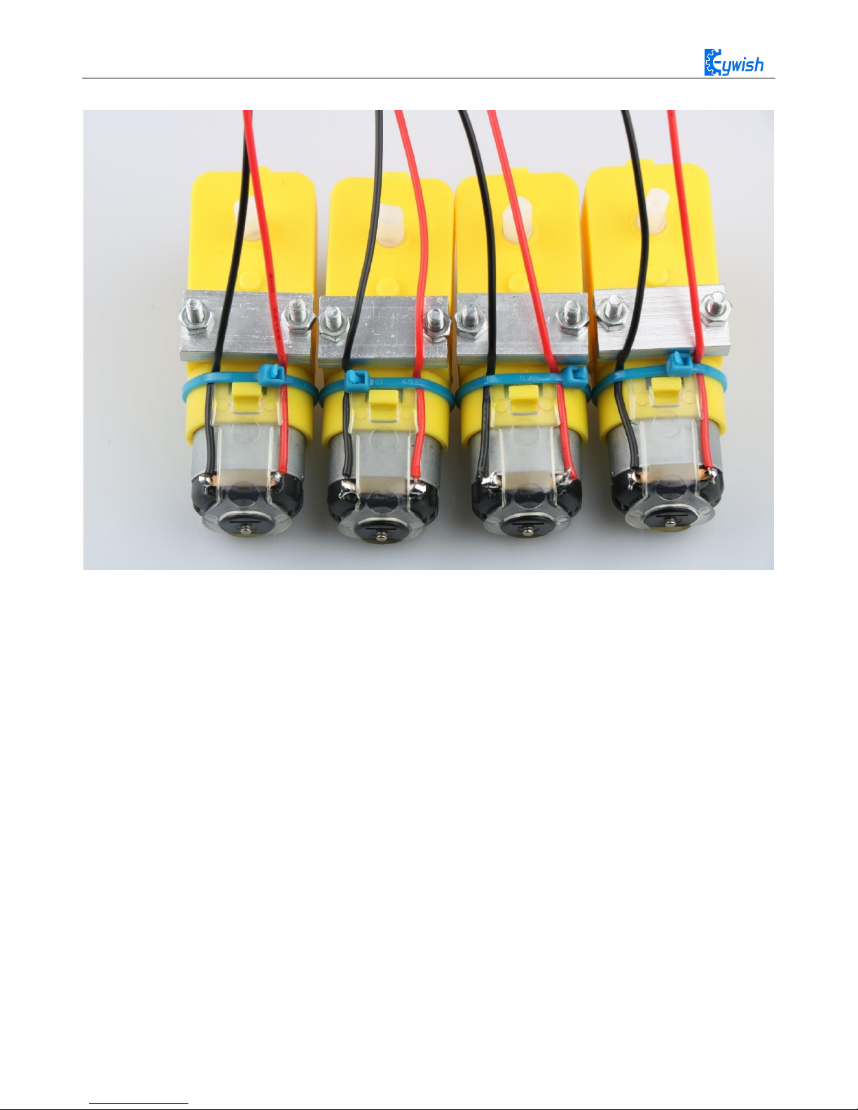
The third step is to fix the wire on the motor with tie tape.
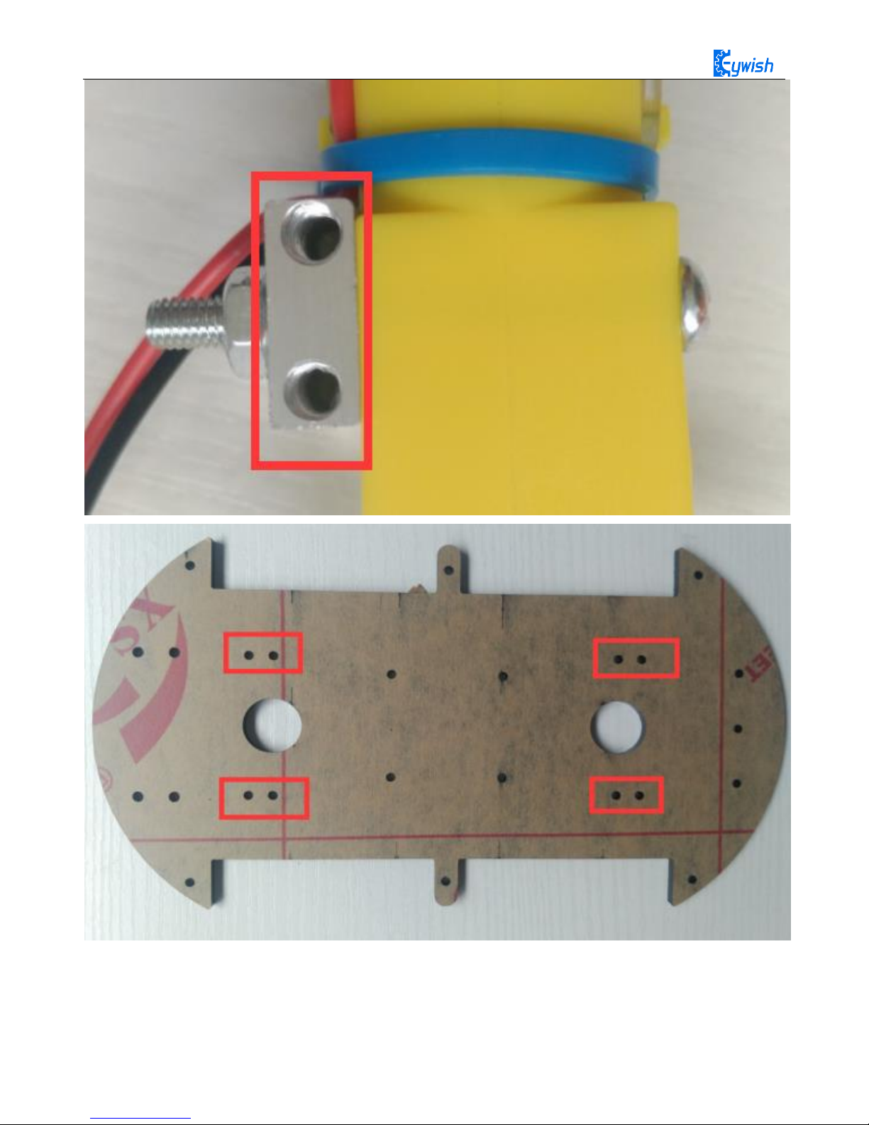
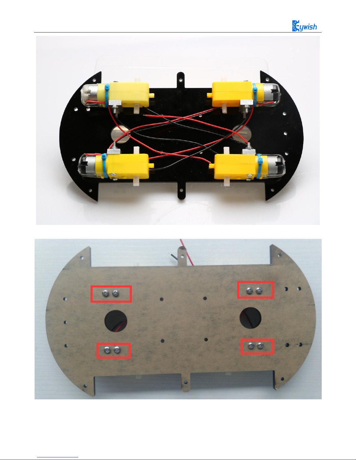
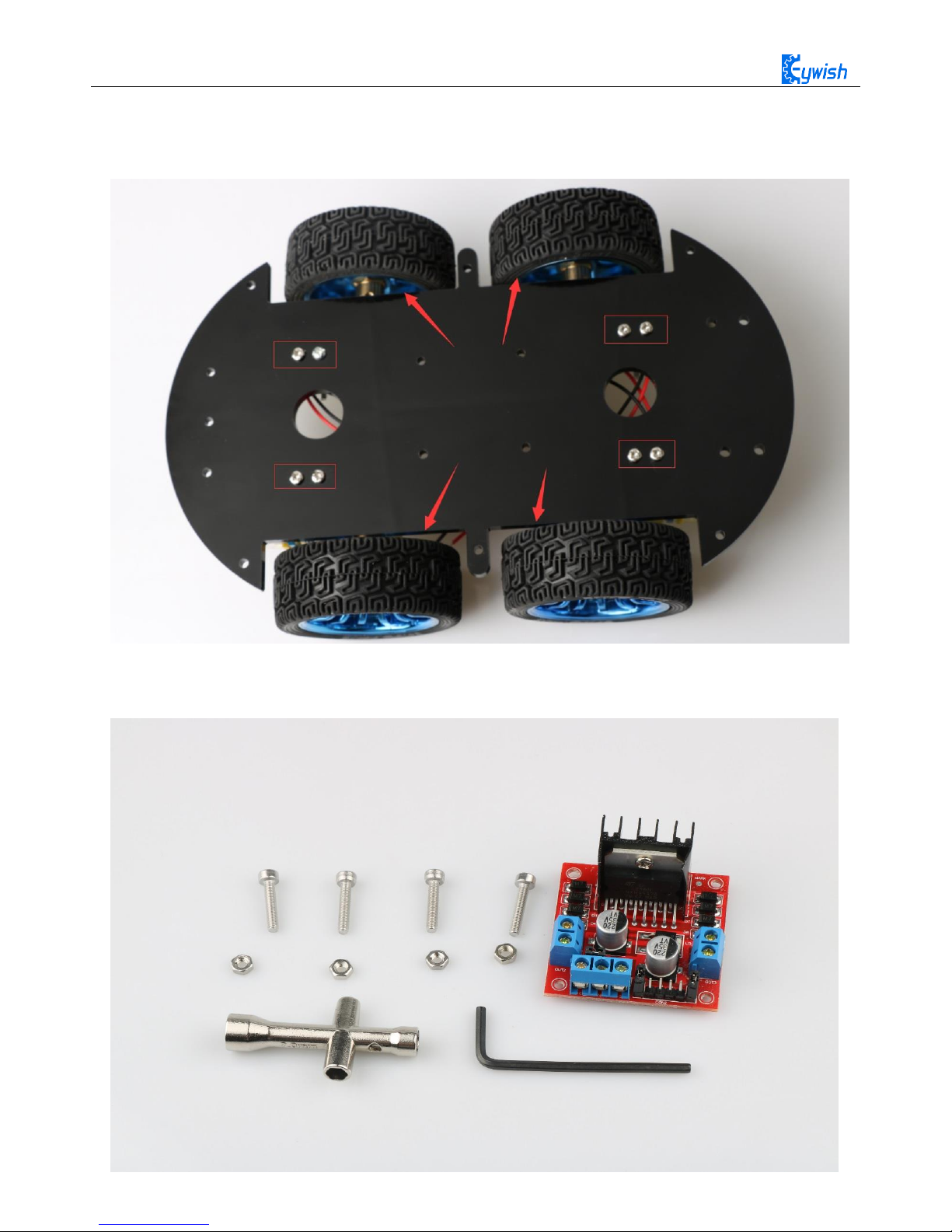
The fourth step is to Mount aluminum alloy brackets on acrylic plates. first removing the protective film on
the acrylic, and then fixing it according to the corresponding space. After the installation, the front face is
shown in Fig.3.1.4, and the back is shown in Fig.3.1.5.
Note: the screws in Fig.3.1.5 should not be screwed too tight, otherwise the wheels adjustment will be
affected. The screw of the motor holder is always installed from the outside to the inside. If it is installed in
the opposite direction, the protruding screw will affect the rotation of the wheel.
the installation must ensure that the screw hole on the bracket aligns with the screw hole on the acrylic
plate
16
Fig.3.1.3 Diagram of Aluminum Alloy Bracket Installation
17
Fig.3.1.4 Diagram of Motor Installation
Fig.3.1.5 Fixing Screw for Motor
18
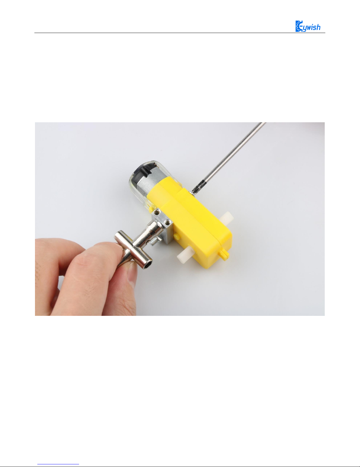
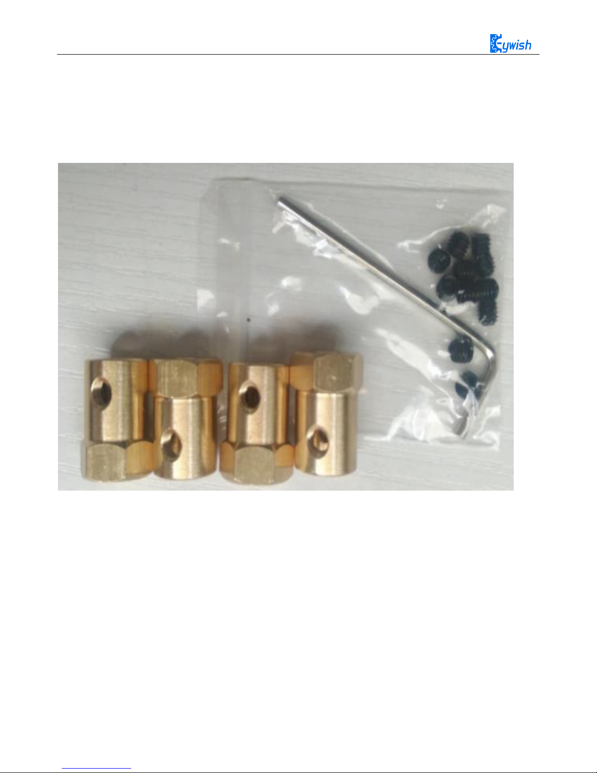
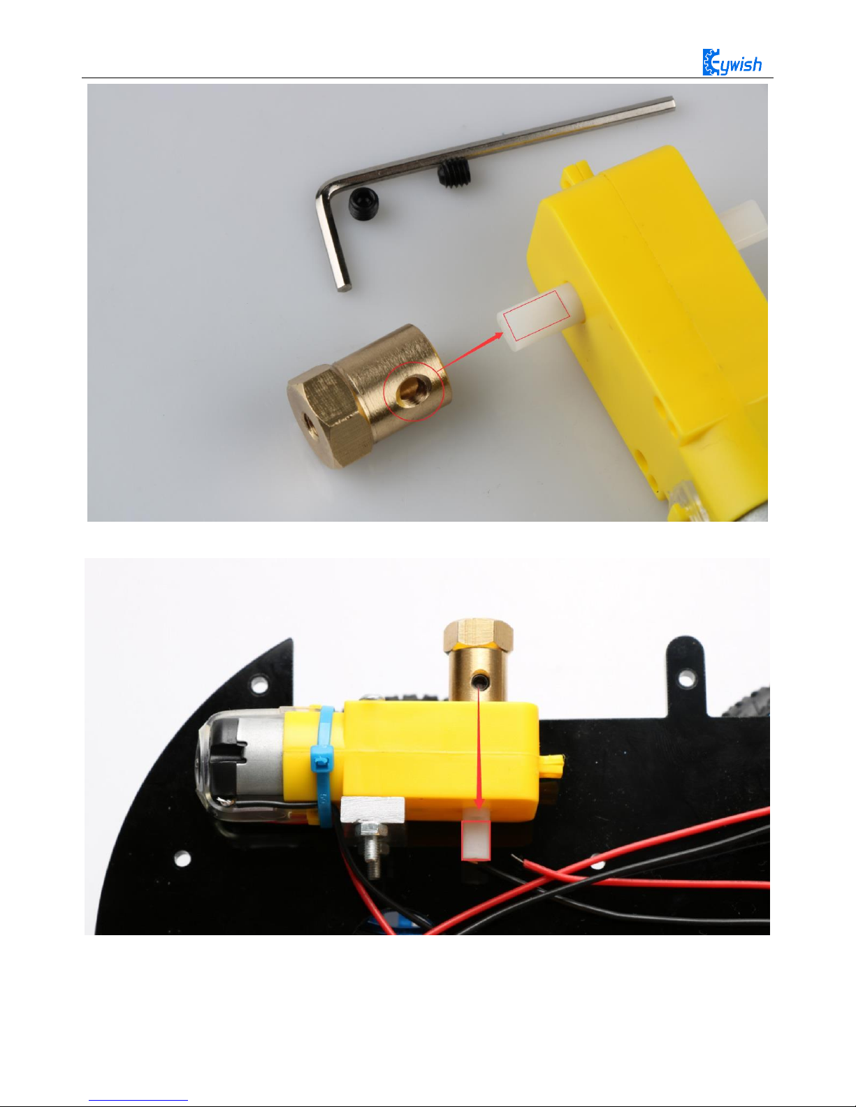
The fifth step is to install the connecting shaft for the purpose of fastening the connecting motor and the
wheel, and use the connecting shaft as the power transmission link. Fig.3.1.6 shows the connecting shaft and
the set screws, first screwing the screws into the connecting shaft (not too tight, otherwise the motor
transmission shaft cannot be inserted into the connecting shaft), Then insert the smooth side of the motor's
drive shaft into the machine screw, as shown in Figure 3.1.7. Turn the machine's meter screws to hold the
smooth side of the motor's drive shaft.
Fig.3.1.6 Connecting Shaft Kit
19
Fig.3.1.7 Diagram of Connecting Shaft Installation
Fig.3.1.8 After Installation (set screws must be stuck in the smooth side)
20
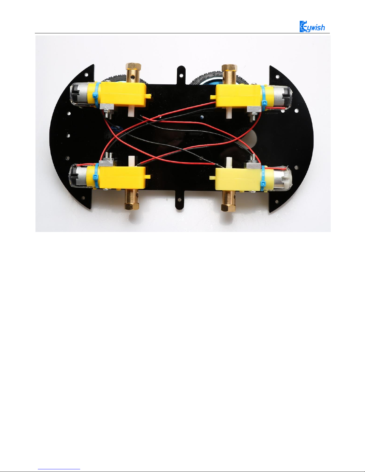
Fig.3.1.9 Diagram after Complete Installation
The sixth step is to install wheels, "Hummer-Bot" uses racing wheels which grip stronger, less friction,
more stable than the traditional wheels. The wheel mounting method is relatively simple. Then inserting the
connecting shafts into the wheels as shown in Fig.3.1.10 and screwing tightly as shown in Fig.3.1.11.
21
Fig.3.1.10 Diagram of Wheel Installation
Fig.3.1.10 Diagram of Wheel Screw Fixation
22
In the fourth step we said that don't screw too tight, because it is not convenient to adjust the wheels
later. As shown in Fig.3.1.11,the installed wheels would have some tilt, then we need to adjust the motor by
hand gently until the wheels and the acrylic become parallel, then tighten the screws.
Fig.3.1.11 Adjusting Wheels and Tightening Screws
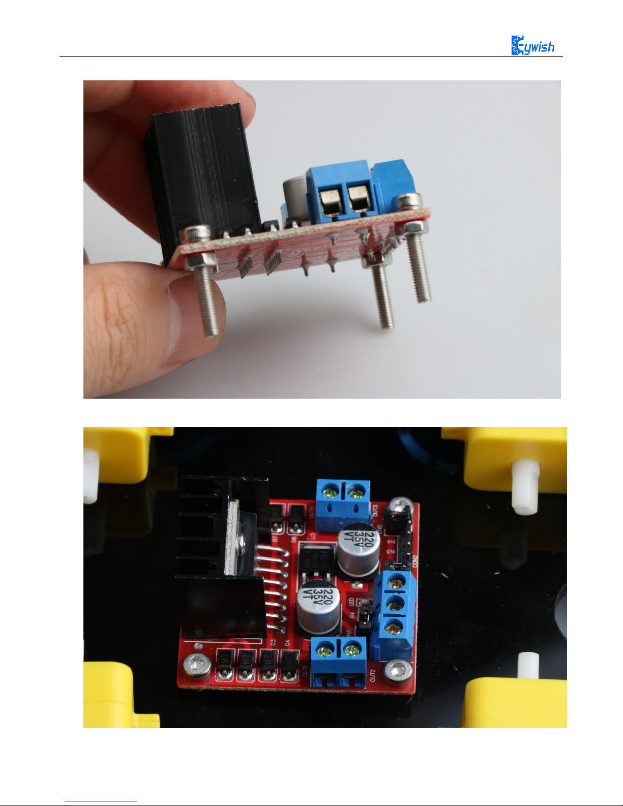
The seventh step is to install the motor drive. As shown in Fig.3.1.12, fixing the motor on the acrylic.
23
First fix the screw on the motor driver board, as shown below
Then install the motor driver board on the acrylic board, as shown below
Fig.3.1.12 Diagram of Motor Drive Installation
24
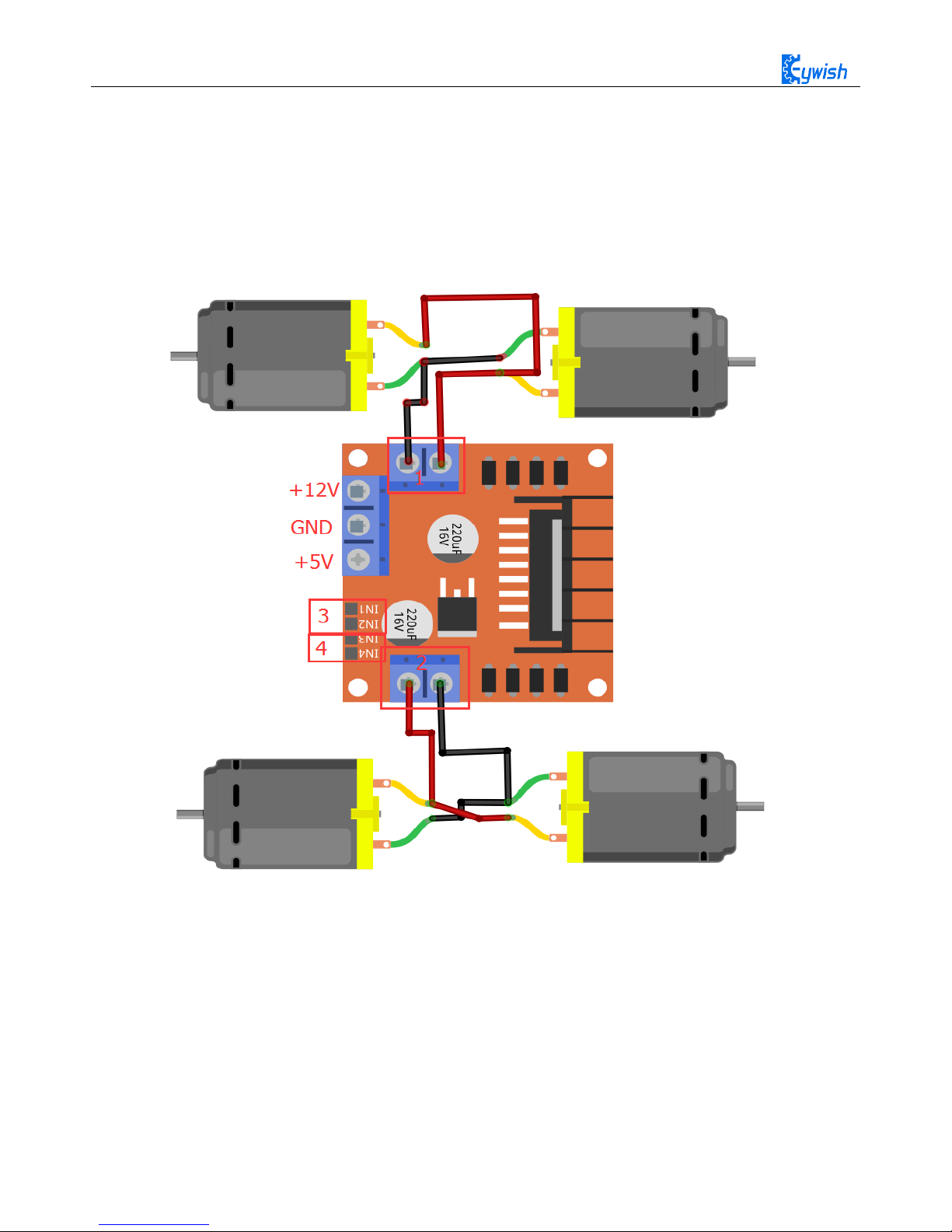
The eighth step is to connect the motor wires to the drive, note that the rotation direction of the two
motors require to be identical, so we should modify and debug the program first when wiring. Connecting the
motor to any motor driver board, as shown in Fig.3.1.13, then connecting the two wires on battery box to the
motor drive +12v (red) and GND (black), and leading a wire from +5V to "3" or "4" in the figure(IN1&IN2
is a motor set, IN3&IN4 is another set). Observing rotation directions of the motors, if the rotation directions
are not the same, you only need to change "1" and "2" in the figure. The physical map is shown in Fig.3.1.14.
Fig.3.1.13 Diagram of Connection Between Motors and Drive Board
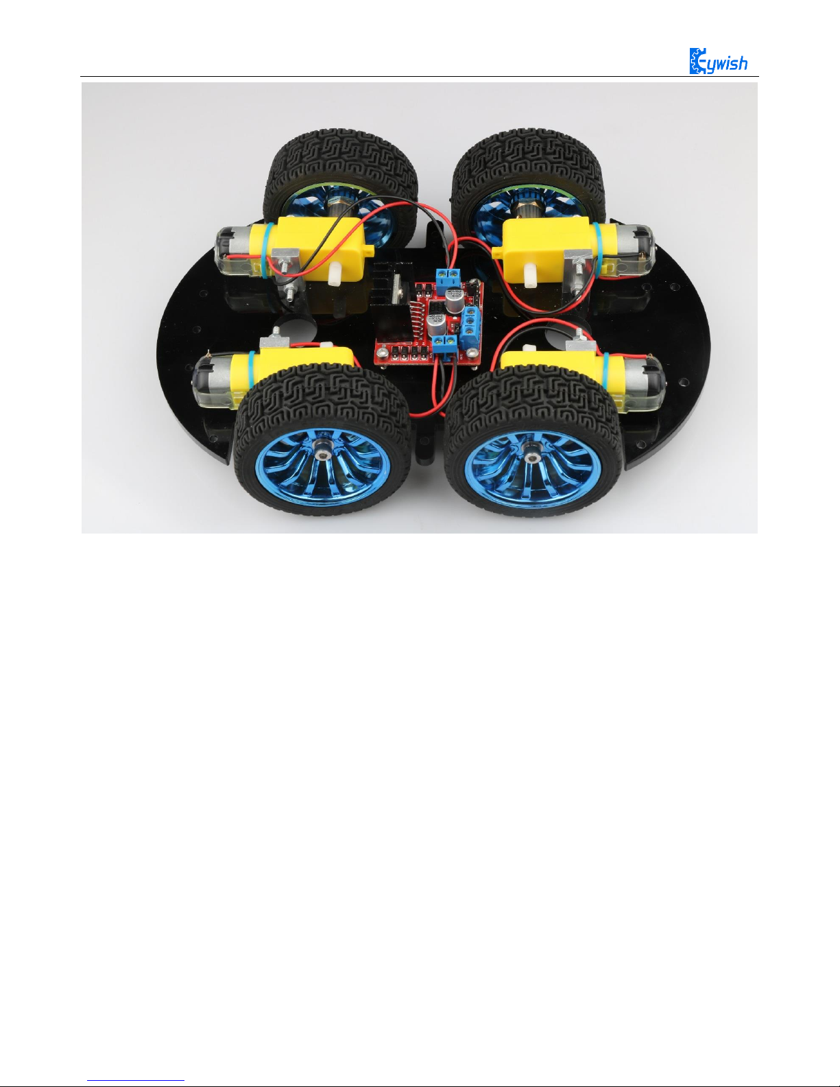
25
Fig.3.1.14 Diagram of Connection Between Motors and Drive Board
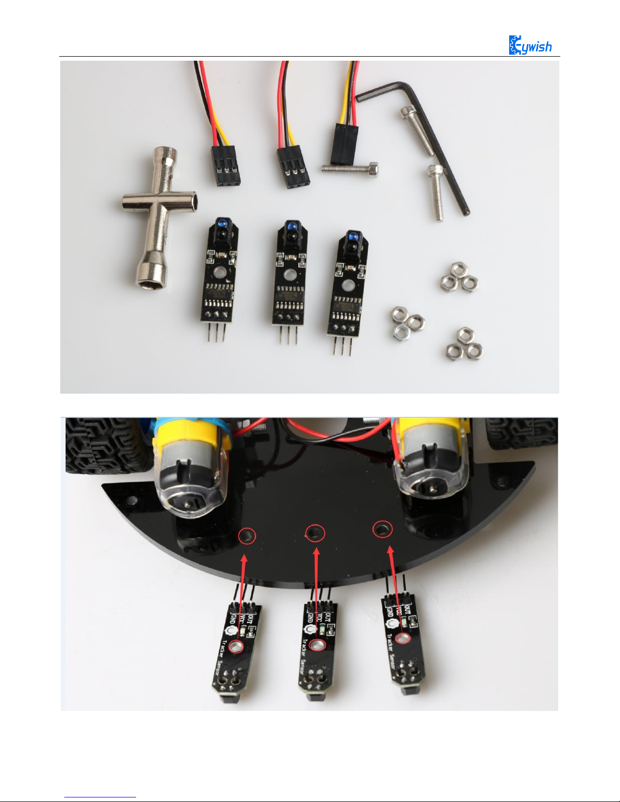
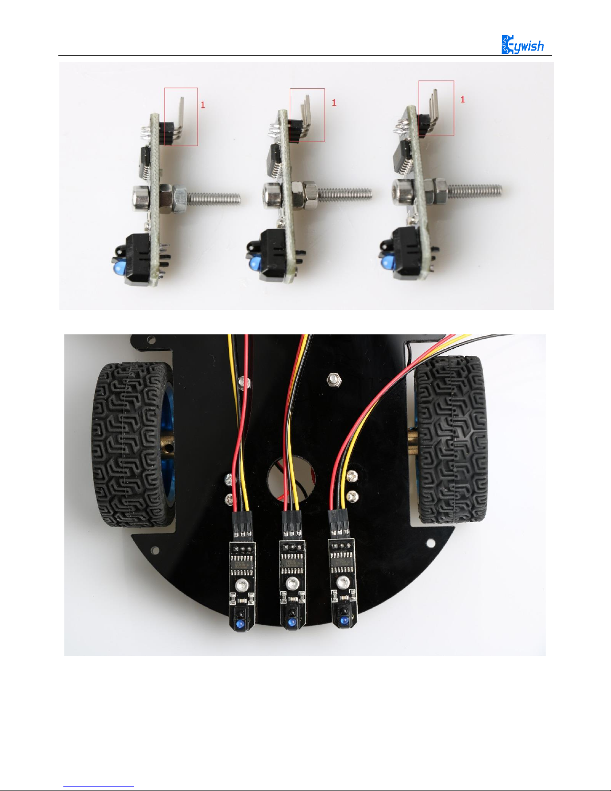
The ninth step is to install the tracing module and fix the module to the acrylic board according to the
Fig.3.1.15. First, screwing the screws to the tracing module(Use two nuts here), as shown in Fig.3.1.16, and
then connecting the 3Pin wire to the "1" in Fig.3.1.16. After the installation is completed, Finally, the tracking
module is fixed to the acrylic plate. the back is shown in Fig 3.1.17 .
26
Fig.3.1.15 Diagram of Tracing Module Installation
27
Fig.3.1.16 Diagram of Screw Brackets
Fig.3.1.17 The Back of Complete Installation
 Loading...