

KeyWest Networks OR100 Series, APOR100-B18, APOR100-X00, APOR100-C23, APOR100-C18 User Manual

OR100 Series User Material
1

OR100 Series User Material
Table of Contents
Chapter 1: Introduction Page No.
1.1 About This User Guide……………………………………………………….…..…..7
2.1 FCC User Information………………………………………………………..….….8
3.1 Professional Antenna Installation Instructions………………………..…….…..9
4.1 Typical Outdoor Installation of Radios………………………………….…........10
5.1 Certified Antenna Gain and Tx Power values……………………………..……..11
6.1 Safety Precautions………………………………………………………………..…13
7.1 Product Overview…………………………………………………………………...14
8.1 Product Key Features………………………………………………………………..14
Chapter 2: Device Configuration
9.1 Power On-Device……………………………………………………………..…….15
10.1 PC Configuration ……………………………………………………………..…….15
11.1 Device Access Types………………………………………………………..……...16
12.1 Login Process…………………………………….…………………………..……..16
13.1 Quick Configuration………………………………………………………..……….19
14.1 Graphical User Interface…………………………………………………..……….20
2

OR100 Series User Material
Chapter 3: Quick Start Page No
15.1 System……………………………………………………………….…….…….….….21
15.1.1 IP Configuration……………………………………………….…..………..21
15.1.2 VLAN Configuration……………………………………………..….………22
16.1 Location……………………………………………………………….………..….…..24
17.1 5 GHz Radio Configuration………………………………..…….…….…..….……..25
18.1 2.4 GHz Radio Configuration………………………………..…….….….…..……..26
19.1 Site Survey…………………………………………………………….…….….……..27
20.1 Link Statistics.…………………………………………………………….……..…….28
Chapter 4: Wireless Configuration
5 GHz Radio Configuration.…………………………………………………….……..…….29
21.1 Properties.………………………………………………………..……….……..….29
22.1 MIMO.………………………………………………………..………..….…………31
23.1 DDRS /ATPC.………………………………………………..………..….…….…….32
24.1 Security.………………………………………………..………..……….………....33
25.1 MAC-ACL………………………………………………..………..……….…….…..33
26.1 DCS………………………………………………..………..………………..……...34
2.4 GHz Configuration………………………………………………..………..….….…….35
27.1 Properties………………………………………………..………..………….…..…35
3

28.1 Security ………………………………………………..………..……………….…36
29.1 MAC-ACL………………………………………………..………..…………………37
Chapter 5: Network
30.1 IP Configuration………………………………………………..………..…………38
31.1 Radius…………………………………………………..………..………………….39
32.1 Static Routes…………………………………………………..………..….……...41
33.1 VLAN…………………………………………………..………..………….……….41
34.1 Ethernet………………………………………………………..………….…………42
OR100 Series User Material
35.1 DHCP Server………………………………………………………..………...…….43
35.1.1 5 GHz Radio……………………………………………..………...……43
35.1.2 2.4 GHz Radio ……………………………………………..…….…....44
36.1 DHCP Fixed Leases………………………………………………………………….44
37.1 Filtering………………………………………………………..………..…….…….45
Chapter 6: Management
38.1 System Configuration………………………………………………………..…….46
38.1.1 General……………………………………………………………..…...46
NTP………………………….…………………………………..…46
GPS………………………….………………………………….….46
Dying Gasp………………………….……………………….…….46
4

38.1.2 Logging………………………….…………………………………..….47
System log………………………….…………………………....47
Temperate log………………………….…………………..…...47
38.1.3 Location………………………….………………………………...…….48
39.1 Services………………………….…………………………………..……………..48
39.1.1 HTTP………………………….…………………………………….……..48
39.1.2 Telnet/ SSH………………………….……………………….………....48
39.1.3 SNMP………………………….………………………………...…….....48
40.1 Upgrade/Reset………………………….………………………………...…......49
OR100 Series User Material
40.1.1 HTTP………………………….………………………………....……....49
Backup & Restore………………………….………………….….……..49
Upgrade Firmware………………………….……………….…….…...49
40.1.2 TFTP………………………….………………………………….…….....50
40.1.3 Reset………………………….………………………………….….…...51
Chapter 7: Monitor
41.1 Statistics………………………….………………………………..…………..…...52
41.1.1 5 GHz Radio………………………….……..…………………….…….…52
41.1.2 2.4 GHz Radio………………………….………………………….….…..53
41.1.3 Wireless………………………….………………………………….……..53
41.1.4 Ethernet………………………….…………………………………….…..54
42.1 LAN Table ………………………….…………………………………..…….….....55
5

42.1.1 Bridge………………………….…………………………………..….....55
42.1.1 ARP………………………….…………………………………..……..….55
43.1 Logs ………………………….…………………………………..……………..…...56
43.1.1 Wireless………………………….………………………………….……56
43.1.2 Ethernet………………………….………………………………..….....58
43.1.3 System………………………….…………………………………….…...58
43.1.4 Configuration………………………….……………………………...….59
43.1.5 Reboot………………………….…………………………………….……59
44.1 Live Traffic ………………………….…………………………………..…….…...60
OR100 Series User Material
44.1.1 Live connection………………………….……………………….…..….60
44.1.2 Traffic………………………….……………………………….………….60
45.1 Tools ………………………….…………………………………..…………….…..61
45.1.1 Diagnostics………………………….…………………………….....…..61
45.1.2 Site Survey………………………….…………………..……………..….62
45.1.3 Spectrum Analyzer ………………………….…………………….……..63
46.1 Technical Specifications…………………………….…………………….………...64
6

OR100 Series User Material
1. Introduction
1.1 About This User Guide
This guide describes the planning, installation, configuration and operation of the KeyWest Networks
point-to-point and point-to-multipoint wireless radios. It covers OR100 Series. It is intended for use by the
system designer, system installer and system administrator.
Chapter 1: Introduction
Chapter 2: Device Configuration
Chapter 3: Quick Guide
Chapter 4: Wireless
Chapter 5: Network
Chapter 6: Management
Contacting KeyWest Networks
Main website: http://keywestnetworks.com/
Sales enquiries: sales@keywestnetworks.com
Contact Address: KeyWest Networks Limited,
Corporate Headquarters
San Jose, CA -95135
7

OR100 Series User Material
2.1 FCC User Information
Federal Communication Commission Interference Statement
This device complies with Part 15 of the FCC Rules. Operation is subject to the following two conditions: (1)
This device may not cause harmful interference, and (2) This device must accept any interference received,
including interference that may cause undesired operation.
This equipment has been tested and found to comply with the limits for a Class B digital device, pursuant
to Part 15 of the FCC Rules. These limits are designed to provide reasonable protection against harmful
interference in a residential installation. This equipment generates uses and can radiate radio frequency
energy and, if not installed and used in accordance with the instructions, may cause harmful interference
to radio communications. However, there is no guarantee that interference will not occur in a particular
installation. If this equipment does cause harmful interference to radio or television reception, which can
be determined by turning the equipment off and on, the user is encouraged to try to correct the
interference by one of the following measures:
Reorient or relocate the receiving antenna.
Increase the separation between the equipment and receiver.
Connect the equipment into an outlet on a circuit different from that to which the receiver is
connected.
Consult the dealer or an experienced radio/TV technician for help
FCC Caution: Any changes or modifications not expressly approved by the party responsible for compliance
could void the user's authority to operate this equipment. This transmitter must not be co-located or
operating in conjunction with any other antenna or transmitter.
Radiation Exposure Statement:
This equipment complies with FCC radiation exposure limits set forth for an uncontrolled environment. This
equipment should be installed and operated with minimum distance 165cm between the radiator and your
body.
8

OR100 Series User Material
3.1 Professional Installation Instruction
Installation Personal
This product is designed for specific application and needs to be installed by a qualified personal who has
RF and related rule knowledge. The general user shall not attempt to install or change the setting. For
complete RF test reports and regulatory power limits, please see documents under FCC-ID: 2ANBGAPOR100
Installation Location
The product shall be installed at a location where the radiating antenna can be kept 165cm from nearby
person in normal operation condition to meet regulatory RF exposure requirement.
External Antenna
Use only the antennas which have been approved in section Certified Antennas. The non-approved
antenna(s) may produce unwanted spurious or excessive RF transmitting power which may lead to the
violation of FCC limit and is prohibited.
Warning
Please carefully select the installation position and make sure that the final output power does not exceed
the limit set force in relevant rules. The violation of the rule could lead to serious federal penalty.
It is the responsibility of the installer to ensure that when configuring the radio in the United States (or
where FCC rules apply), the Tx power is set according to the values for which the product is certified. The
use of Tx power values other than those, for which the product is certified, is expressly forbidden by FCC
rules 47 CFR part 15.204.
It is the responsibility of the installer to ensure that when using the outdoor antenna kits in the United
States (or where FCC rules apply), only those antennas certified with the product are used. The use of any
antenna other than those certified with the product is expressly forbidden by FCC rules 47 CFR part 15.204.
9
OR100 Series User Material
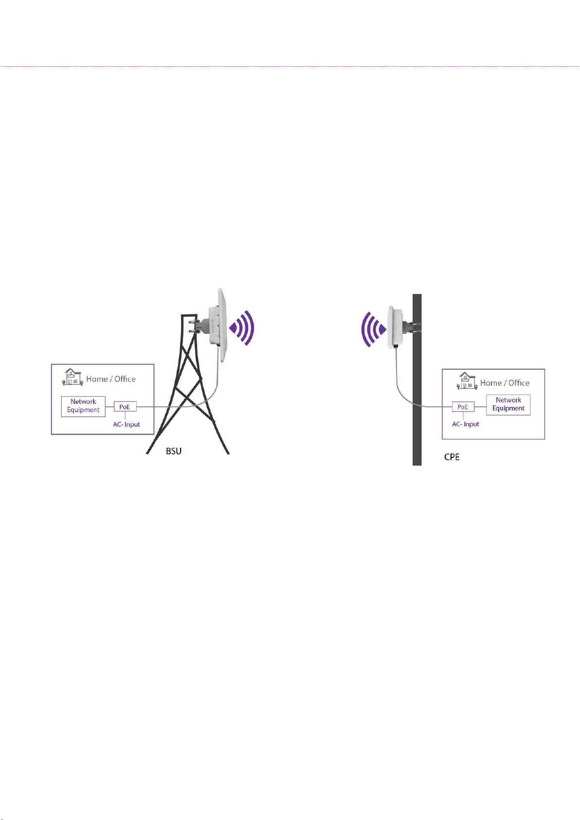
4.1 Typical Outdoor Installation of Radios
KeyWest APOR100 Series products are all outdoor radios installed in one of the following methods:
1. Pole/Tower Mount: Radio installation kit includes two metal hose clamps to support pole sizes
from 30mm to 60mm diameter.
2. Wall Mount: With optional wall mount kit, radios can be installed on the side of the building or a
structure without any obstruction to the radio antenna.
Please see below typical deployment.
10

OR100 Series User Material
APOR100
-
X00 MA-WO56
-
DP10
External, dual pol. Omni
- 11° 10 22
APOR100
-
C23 MA-WA56-
DP23
Integrated dual pol. Panel
- 10° 23 23
5.1 Certified Antenna Gain & Tx Power Values
Antennas shown in the table below or antennas of the same type with lower gain are approved for KeyWest
Radio deployments.
Operating Frequency Band 5725 – 5850 MHz
Marketing Model Antenna P/N Antenna Type Antenna
Gain (dBi)
APOR100-B18 MA-WC56-DP17 Integrated, dual Pol. Sector -
60°
18 14
Tx Power Per
Chain (dBm)
APOR100-C18 MT-485053-CVH-
B_ICD_KW
Integrated dual pol. Panel - 17° 18 23
Operating Frequency Band 5150 – 5250 MHz
It is the responsibility of the installer to ensure that radios operating in the band 5150-5250 MHz are
installed so that they do not exceed 21 dBm EIRP at any elevation angle above 30 degrees as measured
from the horizon, as specified in FCC rule 47 CFR Part 15.407 (a)(1)(i).
This compliance can be achieved through proper selection of radio with antenna, angle of elevation, and Tx
power control to provide reasonable protection for co-channel NGSO/MSS operations.
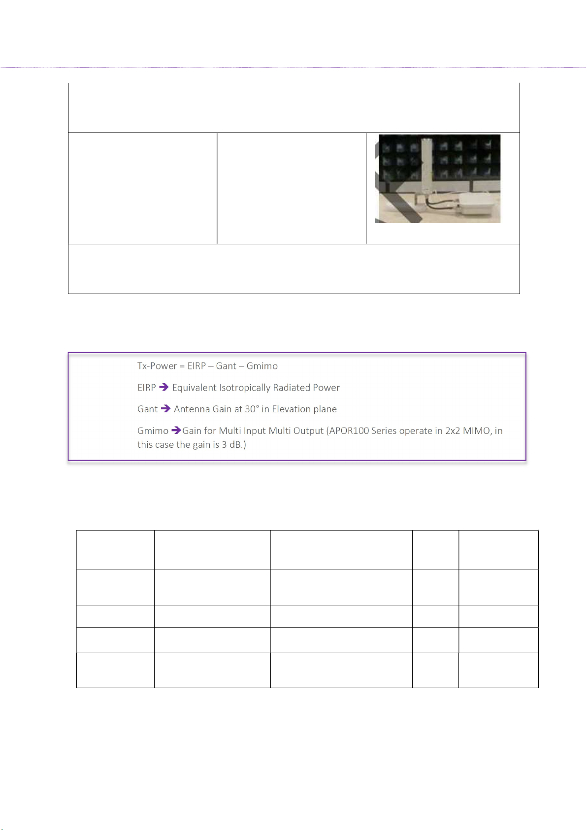
As shown in the typical deployment above, the highest antenna gain from the horizon above 30 degree for
antenna model 1 & 2 is below. For more detail information, please refer to antenna specifications.
Antenna No Antenna Gain Antenna Install Degree
1 0.77dBi
11
OR100 Series User Material
Due to device restrictions installation position is as above picture, thus consider above 30 degrees highest
MA-WO56
-
DP10
10 19
antenna gain is chosen from E-Plane antenna specification of 30-150 degrees, for H- plane antenna gain
will not affect above 30 degrees from the horizon, therefore not required for evaluation.
2
-4.88dBi
Due to device restrictions installation position is as above picture, thus consider above 30 degrees highest
antenna gain is chosen from E-Plane antenna specification of -60-60 degrees, for H-Plane antenna gain
will not affect above 30 degrees from the horizon, therefore not required for evaluation.
The formula used for the calculation of the Transmit Power is given below:
Tx-Power = EIRP – Gant – Gmimo
EIRP Equivalent Isotropically Radiated Power
Gant Antenna Gain at 30° in Elevation plane
Gmimo Gain for Multi Input Multi Output (APOR100 Series operate in 2x2 MIMO, in
this case the gain is 3 dB.)
Antennas shown in the table below or antennas of the same type with lower gain are approved for
deployments in frequency band 5150-5250 MHz with corresponding Transmit Power per chain
configuration in the APOR100 Radios using above formula.
Marketing
Model
APOR100-B18 MA-WC56-DP17 Integrated, dual Pol. Sector -
APOR100-X00
APOR100-C23 MA-WA56-DP23 Integrated dual pol. Panel - 10° 23 10
APOR100-C18 MT-485053-CVH-
Antenna P/N Antenna Type Antenna
Gain
(dBi)
18 10
60°
External, dual pol. Omni - 11°
Integrated dual pol. Panel - 17° 18 10
B_ICD_KW
Tx Power Per
Chain (dBm)
12

6.1 Safety Precautions
Safety Notices
1. Read, follow, and keep these instructions.
2. Heed all warnings.
3. Use attachments or accessories specified by the manufacturer only.
OR100 Series User Material
WARNING:
Do not use this product in a location that can be submerged by water.
Avoid using this product during an electrical storm. There may be a
remote risk of electric shock from lightning
Electrical Safety Information
Compliance is required with respect to voltage, frequency, and current requirements indicated on
the manufacturer’s label. Connection to a different power source than those specified may result in
improper operation, damage to the equipment or pose a fire hazard if the limitations are not
followed.
There are no operator serviceable parts inside this equipment. Service should be provided only by a
qualified service technician.
This equipment is provided with a detachable power cord, which has an integral safety ground wire
intended for connection to a grounded safety outlet.
Do not substitute the power cord with one that is not the provided approved type. Never use an
adapter plug to connect to a 2-wire outlet as this will defeat the continuity of the grounding wire.
The equipment requires the use of the ground wire as a part of the safety certification, modification
or misuse can provide a shock hazard that can result in serious injury or death.
Contact a qualified electrician or the manufacturer if there are questions about the installation prior
to connecting the equipment.
13

OR100 Series User Material
Protective Earthling is provided by Listed AC adapter. Building installation shall provide appropriate
short-circuit backup protection.
Protective bonding must be installed in accordance with local national wiring rules and regulations.
7.1 Product Overview
Overview
OR100 Series of products were tailored for Internet service providers (ISP’s) who wish to deliver
uninterrupted wireless connectivity to Enterprise campuses, Public Wi-Fi, Hospitality, Educational
institutions, Industrial campuses or just about any demanding outdoor environment.
8.1 Product Key Features
Supports IEEE802.11ac/a/b/g/n wireless standards with up to 867 Mbps Data rate
Support Wave 2 MU-MIMO function on 5GHz radio
Perform 256-QAM to enhance data rate
Flexible RF planning with 20,40,80 MHz channel size
Up to 23.5 dBm transmit power enabling long range connectivity
Support Tx Beam forming to enlarge the transmitting distance
Robust housing with IP67 enclosure rated to deploy at extreme weather
Superior QoS with Application aware traffic shaping capability
AES Encryption and Radius Authentication provides the most secure outdoor wireless
communication even in the unlicensed frequency spectrum
Thank you for using OR100 Series. It is a powerful, enhanced, enterprise scale product, which
functions as outdoor Access Point, Base Station Unit and Subscriber Units.
14
2. Device Configuration
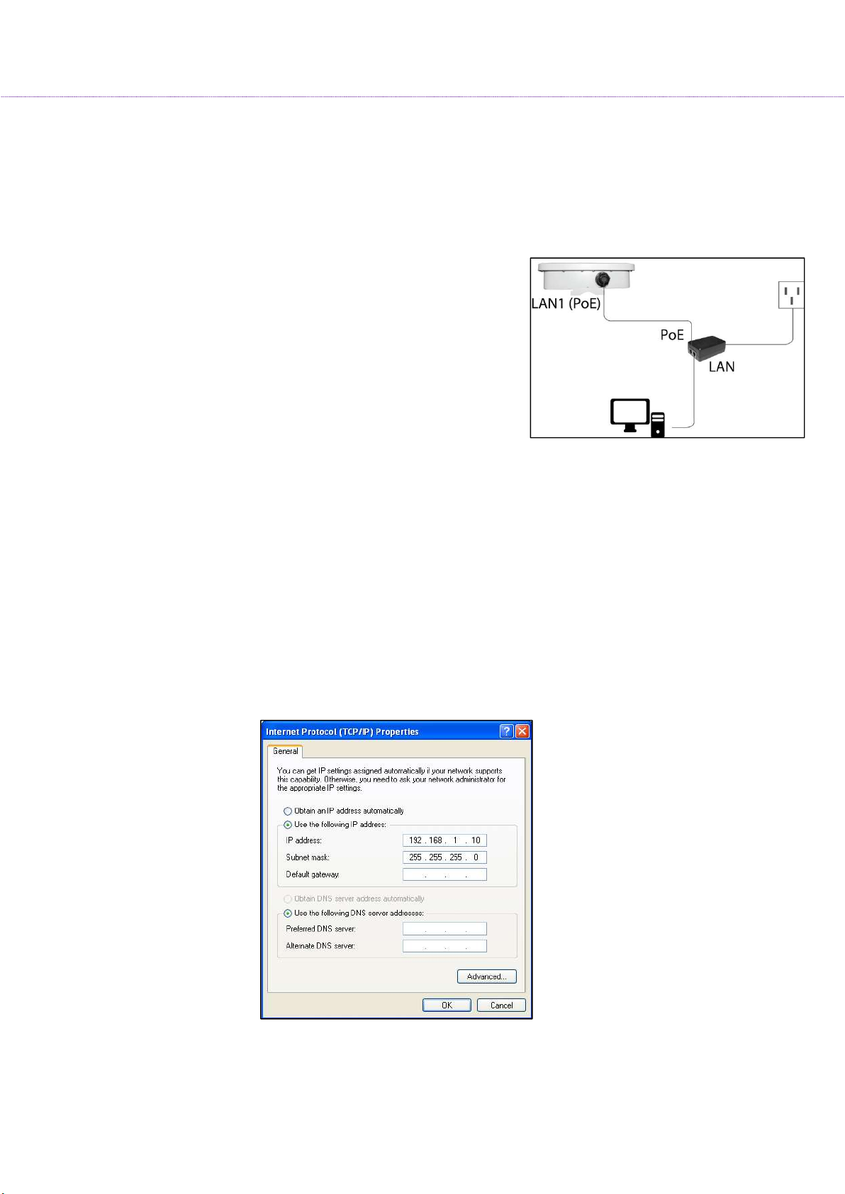
9.1 Power On-Device
Connect the PoE Injector to AC power socket using a power
cord.
Now connect PoE In to PC and PoE Out to the device.
10.1 PC Configuration
OR100 Series User Material
Local PC IP Configuration
Connect the Ethernet LAN cable to the Desktop/Laptop.
Go to Control Panel> Network and Internet settings> Set up a new connection
Configure the Desktop/Laptop with a static IP address of 192.168.1.1 and a subnet mask of
255.255.255.0
Note: The Desktop/Laptop accessing the device must be in the same subnet as that of the device.
15

OR100 Series User Material
11.1 Device Access Types
The Device can be accessed in the following ways:
Access through Ethernet:
During initial setup, use a Wired Ethernet connection from the computer to the device using a PoE.
Access through 2.4GHz Radio Interface:
After the basic network configuration, scan for wireless devices that are available on the network,
default SSID is KeyWest_Wi-Fi with a passphrase as KWN@1234
The device can also be accessed using KeyWest Network Mobile App or using any laptop wireless
connection.
Access remotely over a network:
Once the wireless connection is established, the device can be accessed through a link (PTP or
PTMP) within the network.
12.1 Login Process
Launch any web browser on the PC that is connected to the device.
In the URL type 192.168.1.1 and enter the default credentials as user name: admin and password:
admin
Login and access the device settings
16

OR100 Series User Material
A Network administrator can use the following
interfaces to configure, manage and monitor the device:
HTTP / HTTPS
SNMP
Telnet
SSH
HTTP / HTTPS
The Web interface HTTP provides easy access to configure settings and network statistics from any
computer on the network. The Web interface can be accessed, through LAN, the Internet, or with an
Ethernet cable connected directly to the computer’s Ethernet port.
HTTPS: Enabling HTTPS is to transfer and display web content securely
SNMP
The device can also be configured, managed and monitored by using Simple Network Management
Protocol (SNMP). SNMP is a networking management protocol used to monitor network-attached devices,
which will also collect errors and user statistics.
Telnet
The device can be accessed through CLI by using Telnet, through LAN, or even with an Ethernet cable
connected directly to the computer’s Ethernet port.
To log on to the device using telnet:
Confirm that your computer has IP connectivity with the device
Use telnet client
Log on by entering username and password. The default login credentials are: Username: admin;
Password: admin
17

OR100 Series User Material
Note:
It is recommended to change default passwords after your first login to the device. To change the
password.
Click Management > Services> HTTP > Admin password/ User / Super User/ Installer Password.
Note that only an admin has a right to change the password
The username and password are case-sensitive. If you enter an incorrect password, then a message
is displayed stating that the password is incorrect.
SSH
Enable Secure Shell (SSH) to make secure, encrypted connections in the network. Secure Shell is a network
protocol that allows data to be exchanged using a secure channel between two network devices. The
administrators are required to provide a username, password, port number combination for
authentication.
User Credentials and Roles
The network operator can configure, manage and monitor the device using HTTP/SNMP/Telnet/SSH
protocols. For this, a set of user credentials should be pre-defined for read-write permissions. Based on
user roles the access should be granted. There are four types of users: The admin, super user, user and
the installer.
Admin
The Admin has full access to all the parameters in the settings of the device; this further prevents
unauthorized changes in settings.
Super user
In case of accessing AP, the Super user has a read-only option, where he cannot create, modify or
delete any parameters.
In case of accessing SU, the Super user has read-only permission, but made few custom- limited read-
write permissions for parameters such as Ethernet Speed, VLAN modes (Transparent and Access),
Filtering, Traffic shaping, and Device Reboot.
User
18

OR100 Series User Material
While accessing AP and SU devices, the user has read-only permission, where he cannot create, modify
or delete any parameters.
Installer
The installer does not have full access to Access Point or Subscriber Unit, but he has read-write permission
for a few parameters such as IP configuration, Location parameters, and Radio mode. The installer also
can view site survey scan results (to join any AP) and observe the link statistics status.
13.1 Quick Configuration
This section will show you how to do a quick configuration for both the outdoor Access Point and
Subscriber Units using a web-based configuration interface.
Please refer Devices Access Types or use your Ethernet port or wireless network to access the AP/ SU and
proceed.
After connecting via any one of the three-device access methods, the GUI will prompt you to login with a
password. The default username and password is "admin", and should be changed immediately after login
to protect your network since it gives the user read - write privileges.
The password can be changed:
Click Management > Services> HTTP > Admin password/ User / Super User/ Installer Password.
Web Configuration
Launch any
connected to the device.
In the URL type 192.168.1.1 and enter default
credentials as user name: admin and password:
web browser on the PC that is
admin
Login and
access the device settings in the GUI
19

OR100 Series User Material
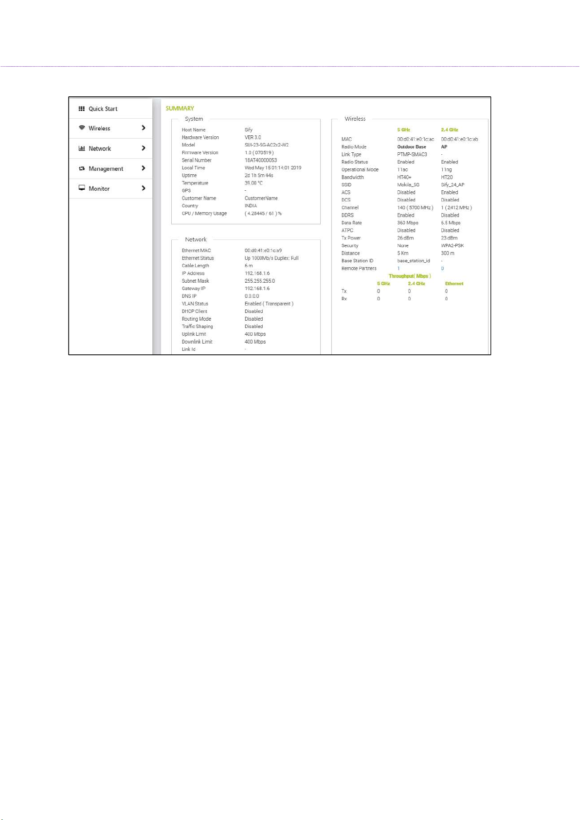
14.1 Graphical User Interface Overview
Power on the Radio to access the Graphical User Interface (GUI). After a successful login, the user notices
a title bar on the top, a navigation pane on the left, and a content pane in the center. The default page
shown in the content pane is the “Summary”.
Home: Click Home to return to the summary page, which displays all the key performance parameters
such as System, Network, Wireless, and Throughput.
Apply: Click Apply to save all changes made to the configuration parameters
Reboot: Click Reboot for changes made in the configuration parameters to take effect. It is mandatory to
click Apply; before Reboot to take effect.
Logout: Click Logout when necessary, make sure to click Apply to save the most recent updates.
Again, the login page is popped-out after a successful logout.
20
OR100 Series User Material
21
 Loading...