

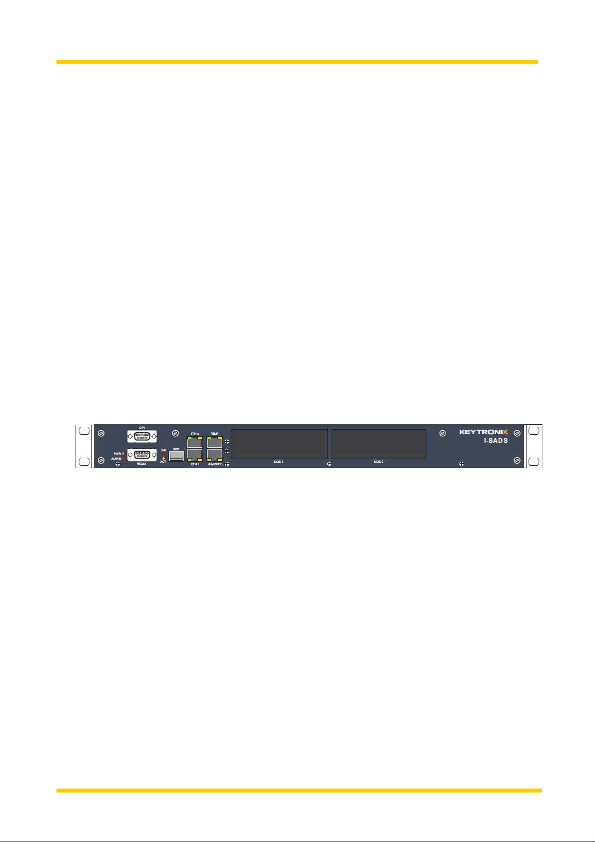
KEYTRONIX I-SAD 19""-S Operating Instructions Manual
Introduction
I –SAD 19”-S
IP Security Access Device for 19” installation
Operating Instructions Version 1.9/SW 2.2
1

Introduction
Impressum:
KEYTRONIX
Gesellschaft für industrielle Elektronik und
Informationstechnologie mbH
Ungargasse 64-66/1/109
A - 1030 Vienna
Tel.: + 43 (1) 718 06 60 - 0
Fax: + 43 (1) 718 06 60 - 820
e-mail:
www.keytronix.com
office@keytronix.com
HG Wien FN 261131t
2

Introduction
Table of Contents
1 I
NTRODUCTION
...................................................................... 4
2 I - SAD 19 "- S O
2.1 Common Features....................................................................... 8
3 RS 232 I
4 I - SAD M
4.1 I-SAD M I/O Modul..................................................................... 13
4.2 ISAD MI/O D-sub Modul............................................................ 18
4.3 I-SAD MCC Modul...................................................................... 23
4.4 AlEx – Alarm Extender.............................................................. 25
5 I
NSTALLATION
6 C
ONFIGURATION
6.1 WEB OPI..................................................................................... 33
6.1.1 LOGIN.............................................................................................34
NTERFACE
ODULES
VERVIEW
..................................................... 7
............................................................. 12
............................................................... 13
..................................................................... 29
.................................................................. 33
6.1.2 Main menu.......................................................................................35
6.1.3 I-SAD (basic settings)......................................................................36
6.1.4 Temperature Sensor........................................................................ 40
6.1.5 Humidity Sensor.............................................................................. 41
6.1.6 Telnet..............................................................................................42
6.1.7 M I/O Module...................................................................................43
6.1.8 M I/O D-sub Module ........................................................................ 47
6.1.9 MCC Module ...................................................................................51
6.1.10 VLAN SETTINGS............................................................................ 54
6.1.11 VLAN TABLE...................................................................................55
6.1.12 ADMIN Bereich................................................................................57
6.2 OPI – Operator Interface........................................................... 60
7 S
8 A
AFETY CONSIDERATIONS
BBREVIATIONS
.................................................................. 72
.................................................... 71
3
Introduction
1 I
NTRODUCTION
The I-SAD 19” is member of the
product family of
The reliable collection and secure transmission of operational data from
telecom network devices becomes more and more important. Operators face
rapid technology changes to their network infrastructure, creating challenges
for their operational support systems (OSS) to keep up. Individual and flexible
data collection solutions guarantee the optimal use of new transmission
technology to link to remote telecom equipment and sites.
Keytronix develops flexible systems that collect and transport device control,
status and alarm data to and from network operation centres.
The Alarm+Telemetry Controller product family offers optimized solutions
for your monitoring and control applications.
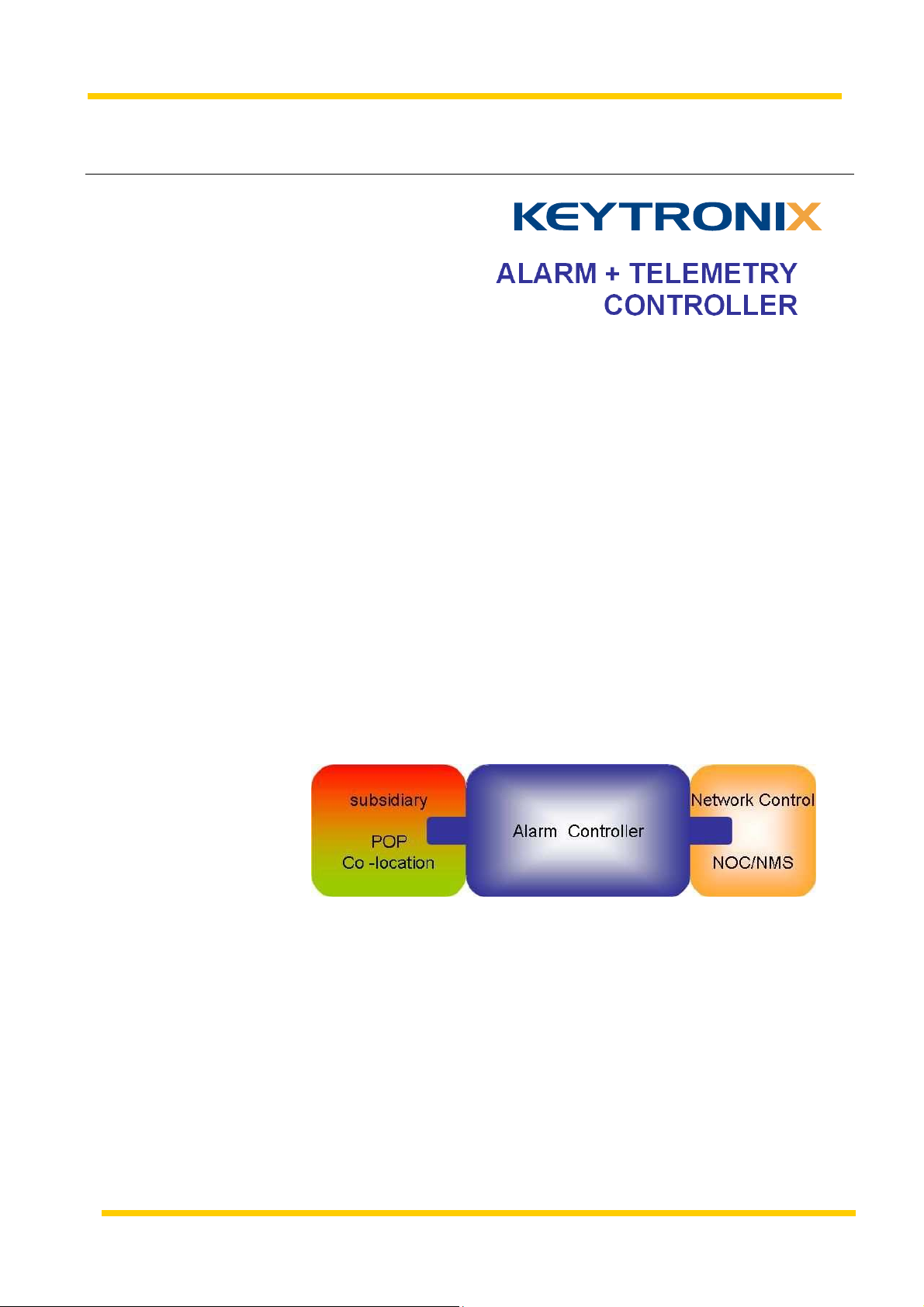
Alarm+Telemetry Controller – what is it?
It is a system that gathers alarms/events and control data of remote devices to a
central management system in a network operations center (NOC).
Figure 1: Alarm controller system overview
The alarm/telemetry controller detects alarms and events and transmits them to the NOC support
systems. It also passes telemetry data and operational control inputs from central management systems
to various equipment and devices installed at the remote sites.
4

Introduction
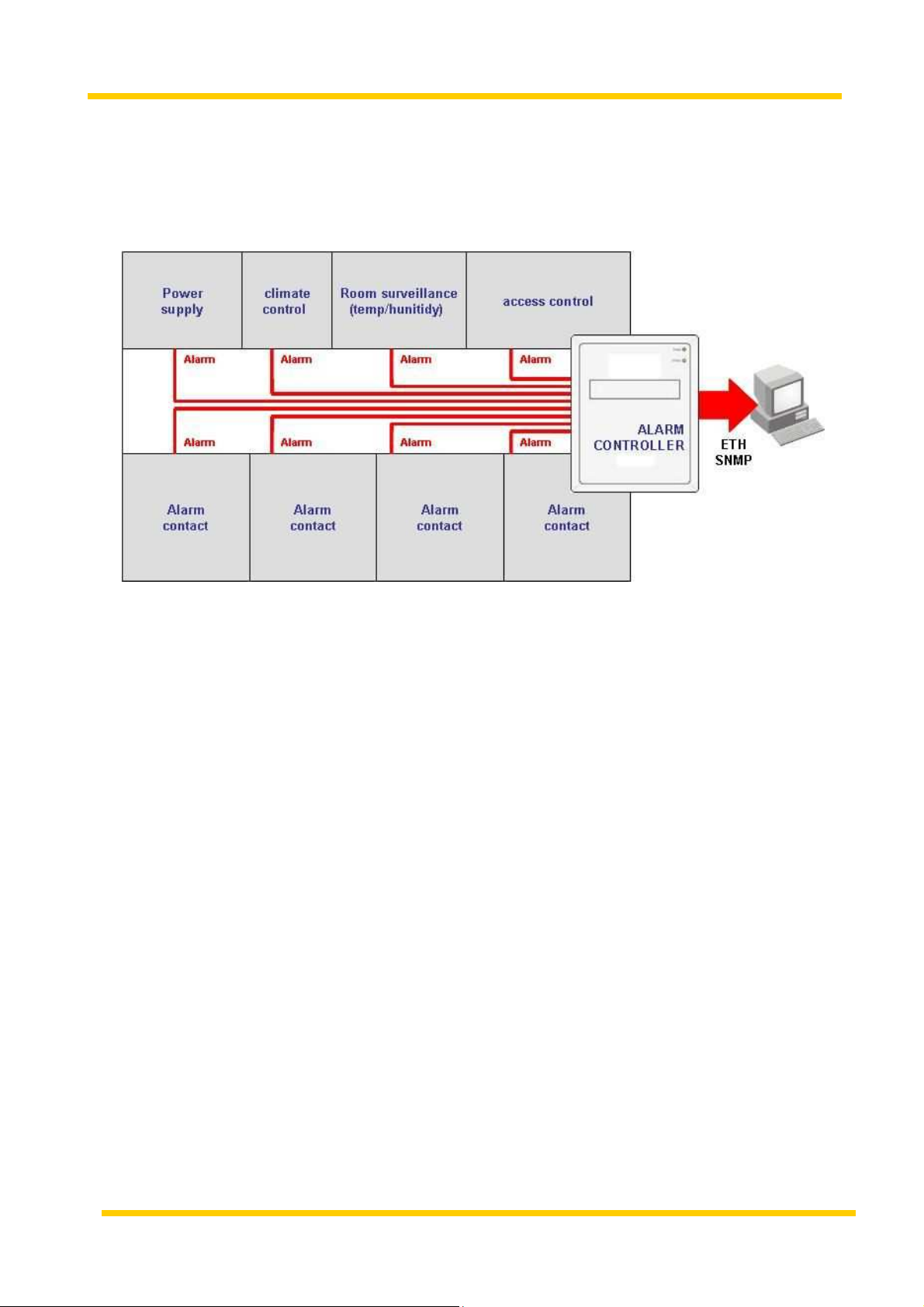
Figure 2: Alarm controller environment
The controller offers a variety of interfaces and connections to suit a wide range of devices. It integrates
easily into various environments through its electrical, Physical and functional connections. This makes
it an ideal choice for remote operation monitoring and remote control of mission critical applications.
Figure 3: Alarm controller functional architecture
5
Introduction
Typical Application:
Remote monitoring and controlling of systems located in an unmanned telecom site
(POP).
Figure 4: Remote site configuration
This includes site security access systems, room surveillance systems, facility
control systems (e.g. climate control, power supply) and telecoms equipment
(e.g. fiber transmission systems, routers, switches, servers and media
gateways). These systems are connected to the alarm + telemetry controller
that transmits events and data bidirectional to the provider NOC.
The controller integrates into existing network management systems and
trouble ticketing systems via the SNMP protocol.
6
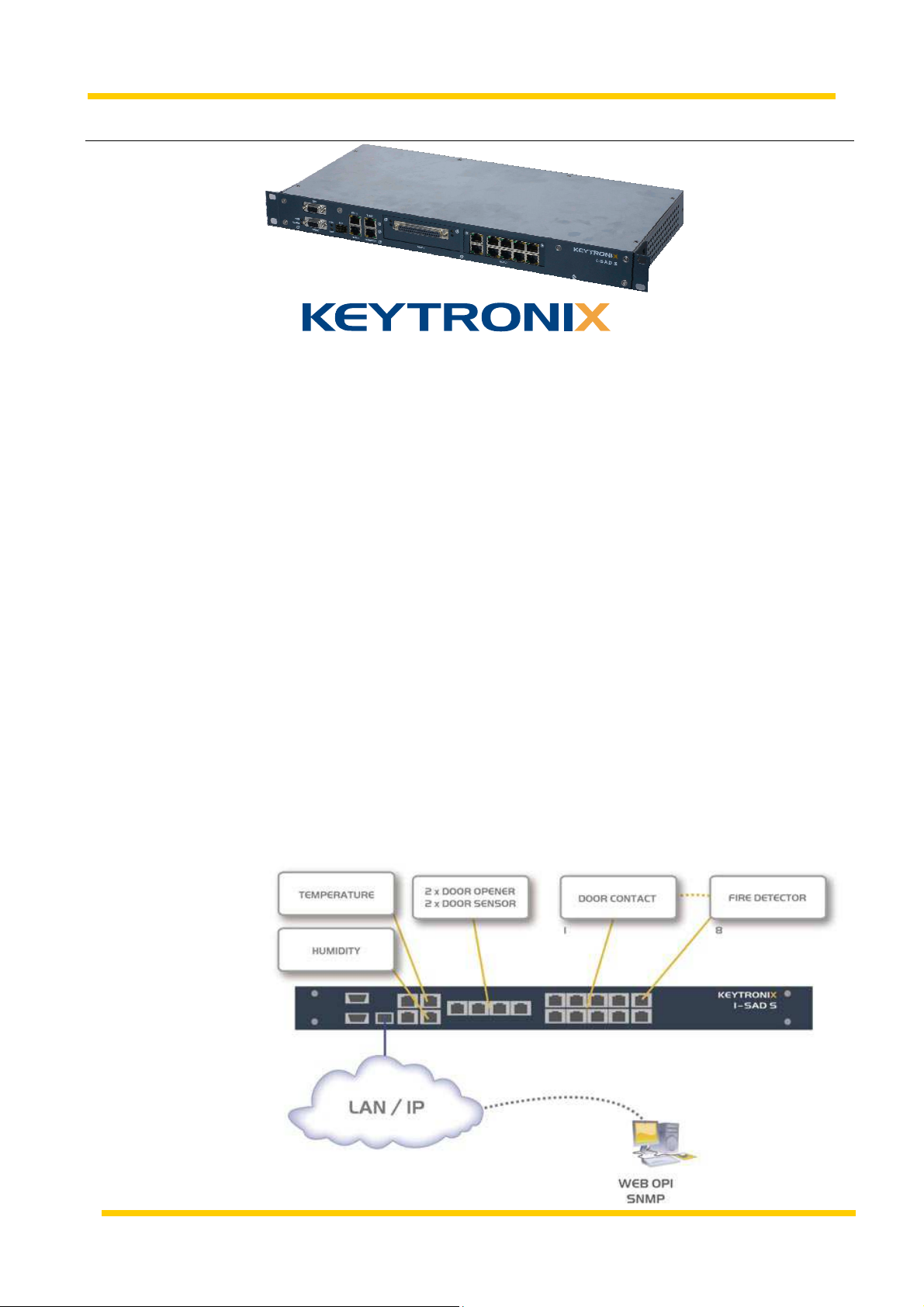
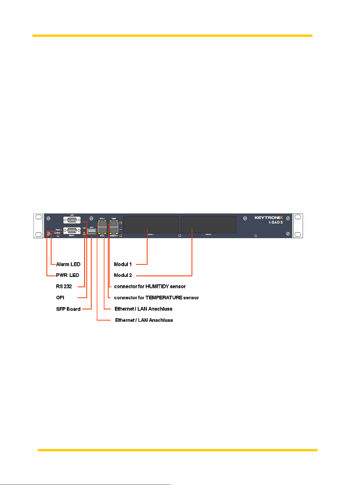
I - SAD 19 "- S Overview
2 I - SAD 19 "- S O
The IP Security Access Device
I-SAD 19“- S is a highly modular remote control system, with the ability to
transmit Alarm data, Switch/Relays Operations and Telemetry-data of the
customer over a secured TCP/IP connection. The connection is established
over Ethernet-LAN or as an alternative wirelessly over an optional M – GSM
over GPRS mountable module.
Additional features are the control of temperature and humidity sensors.
Access to third party equipment (with implemented asynchronous interface)
can be realized by connecting them to RS-232 interface on the I-SAD 19”
front panel.
The configuration, control and evaluation/reporting of the I-SAD 19“device
can be carried over the Ethernet Interface via
VERVIEW
Application
• integrated WEB Operator Interface
• SNMP
or over a local asynchronous Operator Interface (OPI) designed as a
Command Line Interface (CLI).
Connection of external Sensors and/or different peripheral Alarms I/Os for
monitoring and surveillance on a remote IP-Desktop.
7
I - SAD 19 "- S Overview
2.1 Common Features
Management
Physical
Front view
HTML - based WEB OPI
SNMP V2c for sending of event - messages, administration of the device and
remote control of the input and outputs (I/Os).
DHCP client or static IP address
up to 3 destination addresses for SNMP traps possible
free editing of READ/WRITE communities
Form factor: 19” 1HU
Dimensions: 483 x 45 x 205 (W x H x L) mm
8

I - SAD 19 "- S Overview
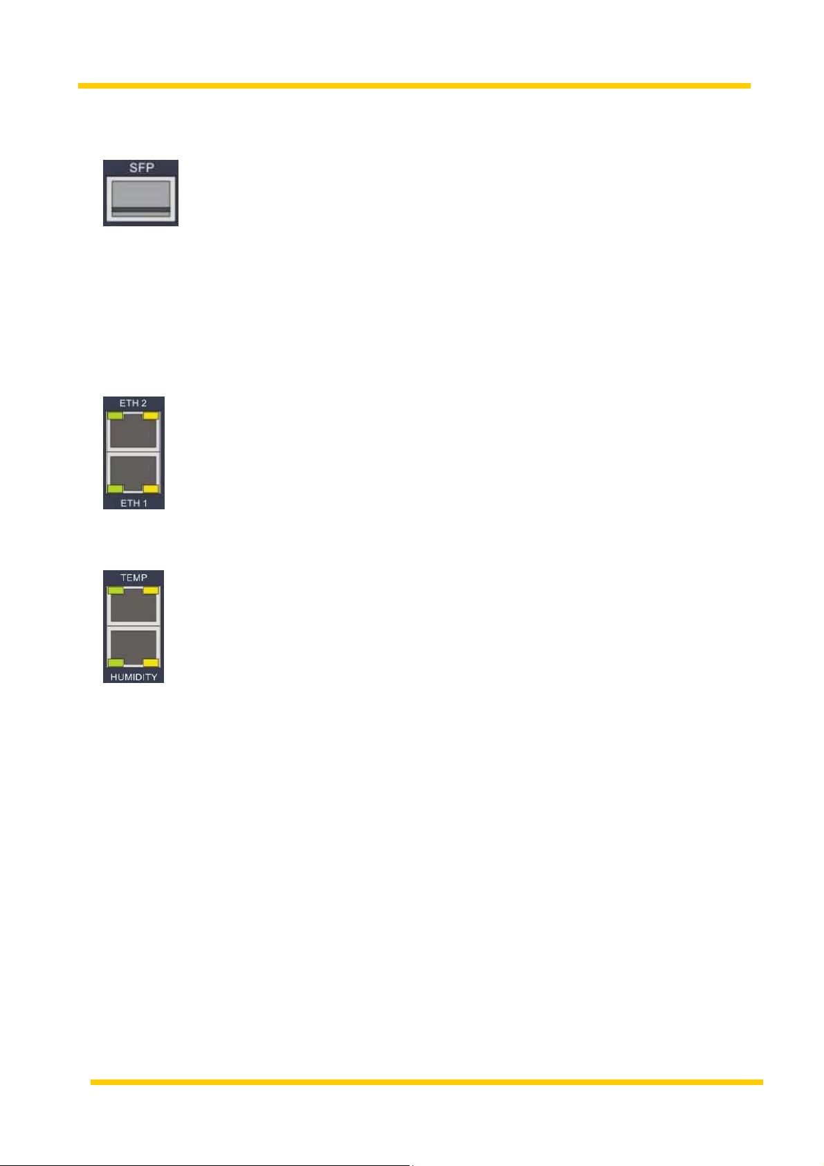
Ethernet Switch:
The I-SAD 19“-S is equipped with an integrated Ethernet - Switch. It is used
to switch the data between the four Ports.
the 4 Ports:
• NMS is an internal Port, which is connected to the CPU.
• ETH1 10/100BT Interface on the front of the device
• ETH1 10/100BT Interface on the front of the device
• SFP Plugin – slot for SFP plugin modules
Technical specification of the Ethernet –Switch:
• Ethertype: 8100 Hex
• Up to 1024 Mac- addresses
• max. Framesize: 1522bytes
• VLAN according to 802.1 Q/P
Displays/ LEDs
- max. 64 different VLANs - entries
- VLAN ID: 0 – 4095
Alarm red Is on if the device detects an alarm
PWR green “Power” is flashing when the device is
booting and lights up if the device is ready for
use
TEMP green Sensor is connected
yellow temperature interval failure
HUMIDITY green Sensor is connected
yellow relative humidity failure
SFP LNK Is on if the line is synchronised
ACT Is on if data is transmitted
Ethernet /
LAN Interface green Link/Act
yellow on = 100, off = 10MBit/s
9
I - SAD 19 "- S Overview
Interfaces
SFP SLOT for one 100FX SFP (Small Factor Plugin) for LAN access
The warranty is satisfied with the following SFP´s:
APACOE LS38-C3S-TI-N-D3 SM1310/1550 10km
IMC 808 -38103 IE-SFP SM1310 20km
IMC 808-38101 IE-SFP MM850 2KM
ETH 1+2 (LAN, WEB-OPI Operator Interface, Ethernet Connector, auto -
detected)
TEMP RJ 45- Connector for connecting a Keytronix I-SAD TS (0708-
6201) or RITTAL temperature - sensor
HUMITIDY RJ 45- Connector for connecting a Keytronix I-SAD HS (0708-
6101) or RITTAL humidity – sensor
10
I - SAD 19 "- S Overview
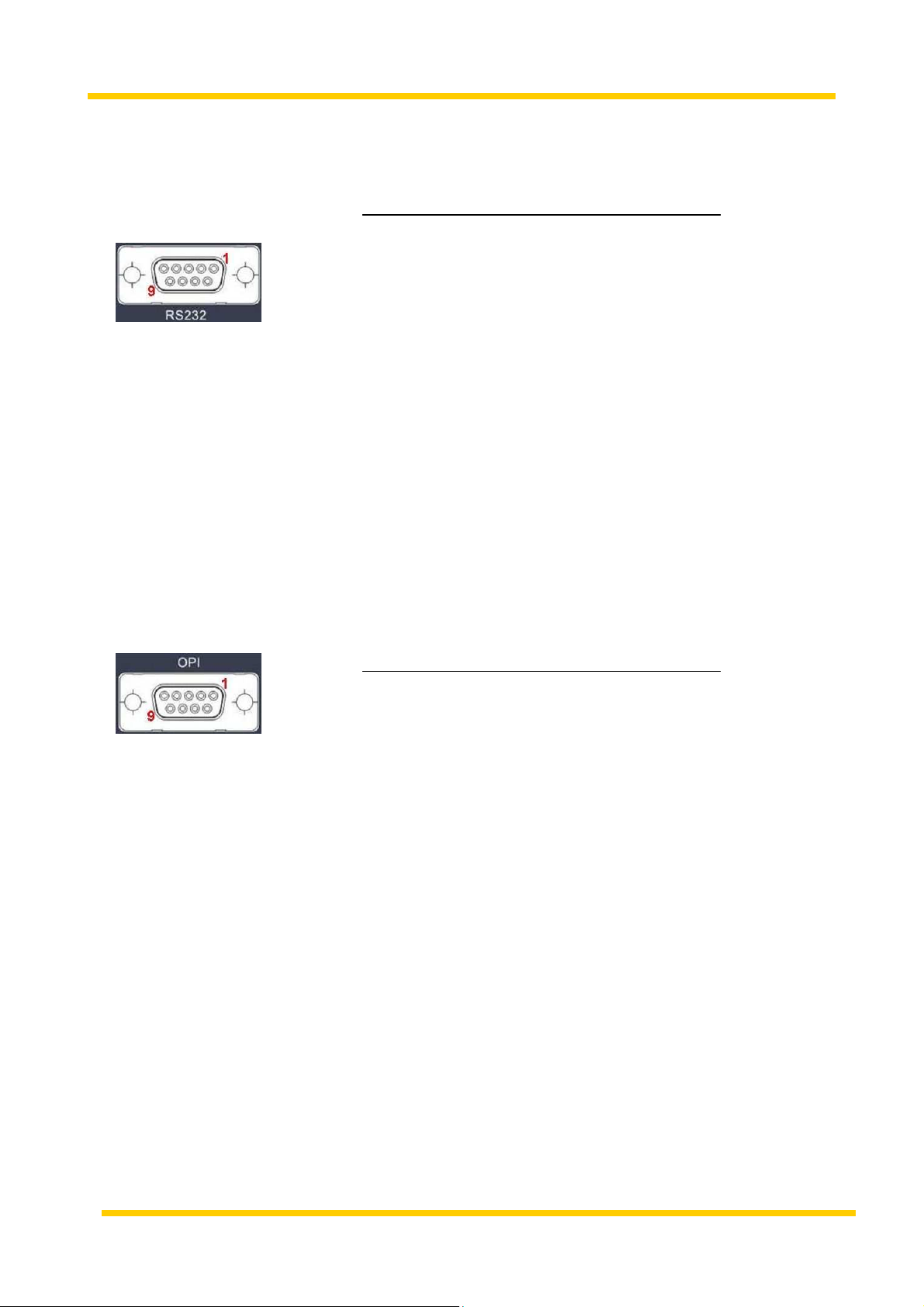
RS 232 Serial asynchronous interface for remote access to an unknown
device, default configuration: 9k6/N/8/1
Pin assignment:
PIN signal direction description
1 0 DCD
2 0 RD
3 I TD
4 I DTR
5 - GND
6 0 DSR
7 I RTS
8 0 CTS
9 - -
Powersupply
OPI Serial OPI (Operator Interface) / CLI (Command Line Interface),
fixed configuration: 115k2/N/8/1
Pin assignment:
PIN signal direction description
2 0 RD
3 I TD
5 - GND
42 V DC – 230 V AC wide-range power – supply, Protection class I
The I-SAD 19“ device is powered by an integrated wide-range power supply.
The device can be powered with DC or AC voltage without any
reconfiguration.
Environmental
Conditions
Operation: -20 °C to + 70 °C
Storage conditions: -20 °C to + 70 °C
relative humidity: max. 80%, not condensing
11

RS 232 Interface
3 RS 232 I
Ist. step
NTERFACE
This Interface is used to make a remote access connection to a third party
equipment via an asynchronous serial interface. The serial data get tunnel
over IP. The interface has a fixed configuration for sending and transmitting
data at 9k6/N/8/1.
ATTENTION: The warranty is satisfied with the following
TELNET Clients:
To get access to that « unknown » device, you must connect to the serial
interface using a cross-over cable (not included at delivery package).
Please take care to use the correct connection settings: 9k6/N/8/1
• TERATERM TELNET Client (Version 3.1.3)
• PUTTY TELNET Client (Version 0.58)
• MS-DOS TELNET Client (Version 5.1.2600.5512 )
• Cygwin TELNET Client (Version 1.5)
2nd. step
.
You can get access to the ISAD-19“ RS232 interface via Telnet using the
ISAD 19” IP address on TCP port 7478.
Recommended procedure:
● start a Telnet session
● e.g.: “Telnet [IP address] 7478 “– ENTER
● establishes a connection and when active, the ISAD responds:
„Hello [IP Address]“
Type „c“ to connect to RS232
ISAD>
Enter „c“ and submit with „Return“ connection is established.
To exit this operation, just close the Telnet Session.
Timeout happens 5 minutes after the last key press.
12

I - SAD Modules
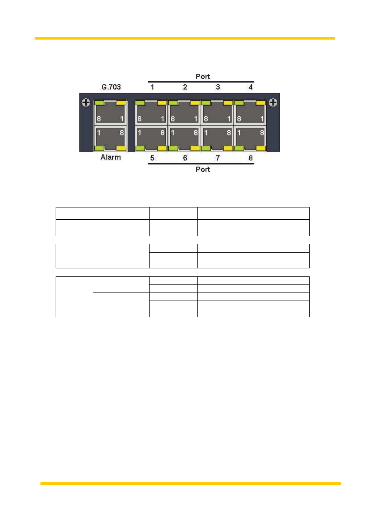
4 I - SAD M
ODULES
4.1 I-SAD M I/O Modul
The I-SAD MI/O Modul
enables the handling of up to 8 I/O (Input / Output) Interfaces.
The MI/O consists of:
• 8 galvanically isolated inputs
• 8 parallel / bistable. potential-free outputs
• Only signals in the low power voltage range can be switched
(EN60950: SELV-circuit).
/ controlled loops
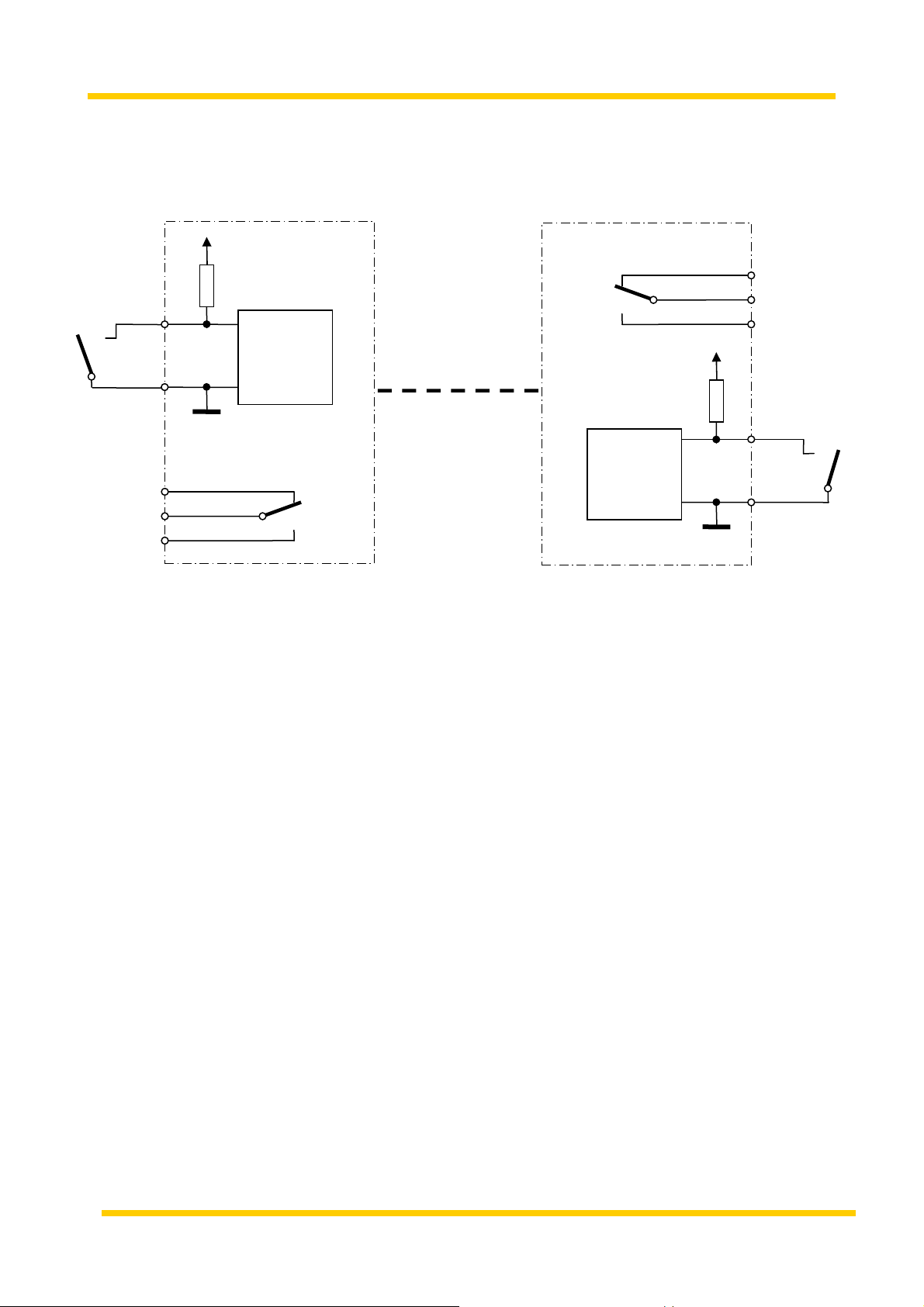
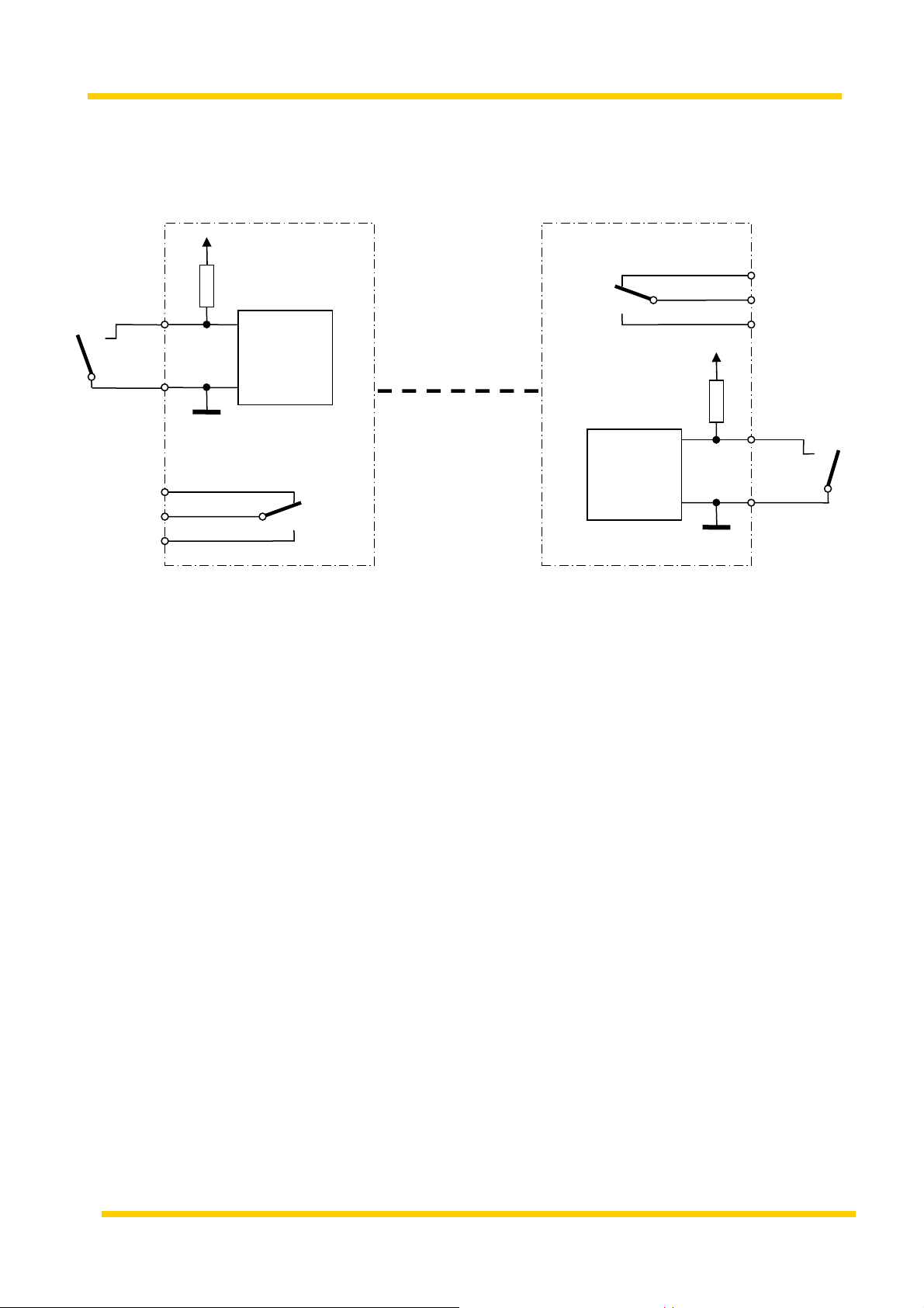
Connectors
Displays / LEDs
• All I/Os are realized on RJ45 connectors, every RJ45
connector consists of one Input (Pin 1, 2) and one output (Pin 6, 7, 8).
• 2 parallel outputs (free of potential) control the operating states.
It uses an RJ45 connector (local alarm Pin 1,& 2, remote Alarm Pin 7 &
8).
• Possibility to connect a Keytronix AlEx device (remote unit) via G.703
interface.
8 I/Os + 1x G703. Link + alarm outputs
10 x RJ-45 Connector
G.703 green transmission - line OK
yellow On if the mode „G.703 used“ is active
and the mode „only output monitoring“ is not
activated.
Alarm (Relay) green On if the connection to the „remote Unit“ is
failed or an error occurs on the transmission line.
yellow On if the module is ready for use.
Ports 1 - 8 green Output is active.
yellow Input is active and/or input criteria is detected.
13
I - SAD Modules
Interfaces
Pin Assignments
Ports 1-8
Name
G.703
Alarm-Relais
Input
Output
Pin # Signal
1, 2 Received Data
4, 5 Transmit Data
1, 2 Closed circuit contact (local alarm)
7, 8 Closed circuit contact (remote
alarm)
1 Input
2 GND
6 Normally open contact
7 Common
8 Closed circuit contact
14
I - SAD Modules
Common
open
circuit
Input
Common
op
en circuit
l
okale
device
(I-SAD)
remote
de
vice (AlEx)
G.703
-
Line
Application
Input
external
contact
Output
working contact
Output
1
supervisiory
2
supervisiory
6
7
8
Working contact
external
contact
15

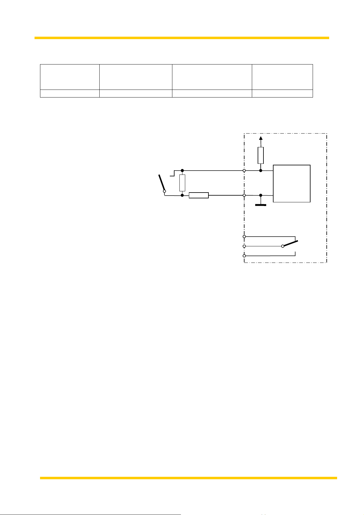
I - SAD Modules
Common
open circuit
R2
Values of resistance for line supervisiory (sabotage monitoring) of
external contacts:
no sabotage,
sabotage,
short circuid
contact closed
no sabotage,
contact closed
Sabotage,
line interruption
<200 >300Ohm … <4kOhm >5kOhm … <9kOhm >20kOhm
Connection of the external contact for line supervisiory contact
external
contact
R1
R1 = >300 … <4kOhm
R1 +R2 = >5k … <9kOhm
Input
Output
working contact
1
supervisory
2
6
7
8
For prove working of line supervisory against sabotage, resistances R1 and
R2 has situated as near as possible at the external contact.
Notice that the line resistance to the external contact is arithmetic part of R1.
16
I - SAD Modules
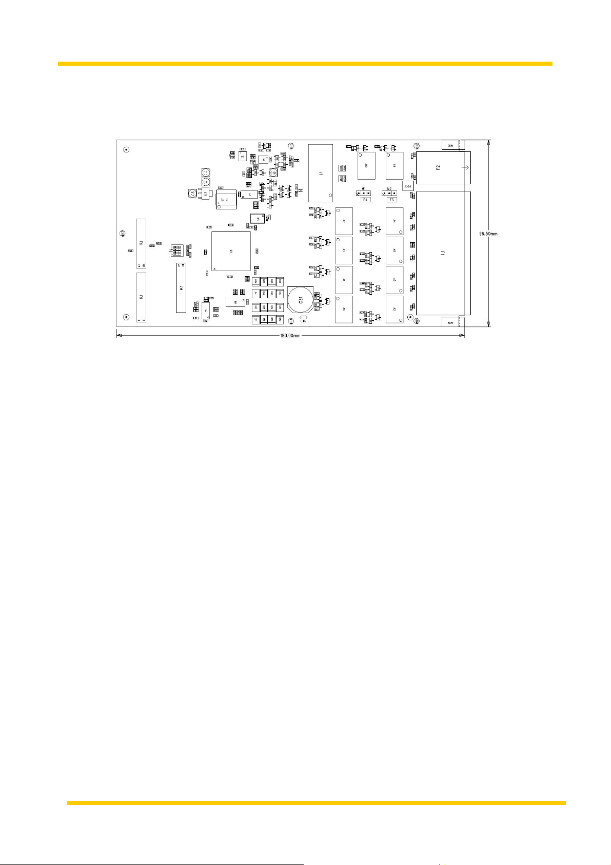
Physical
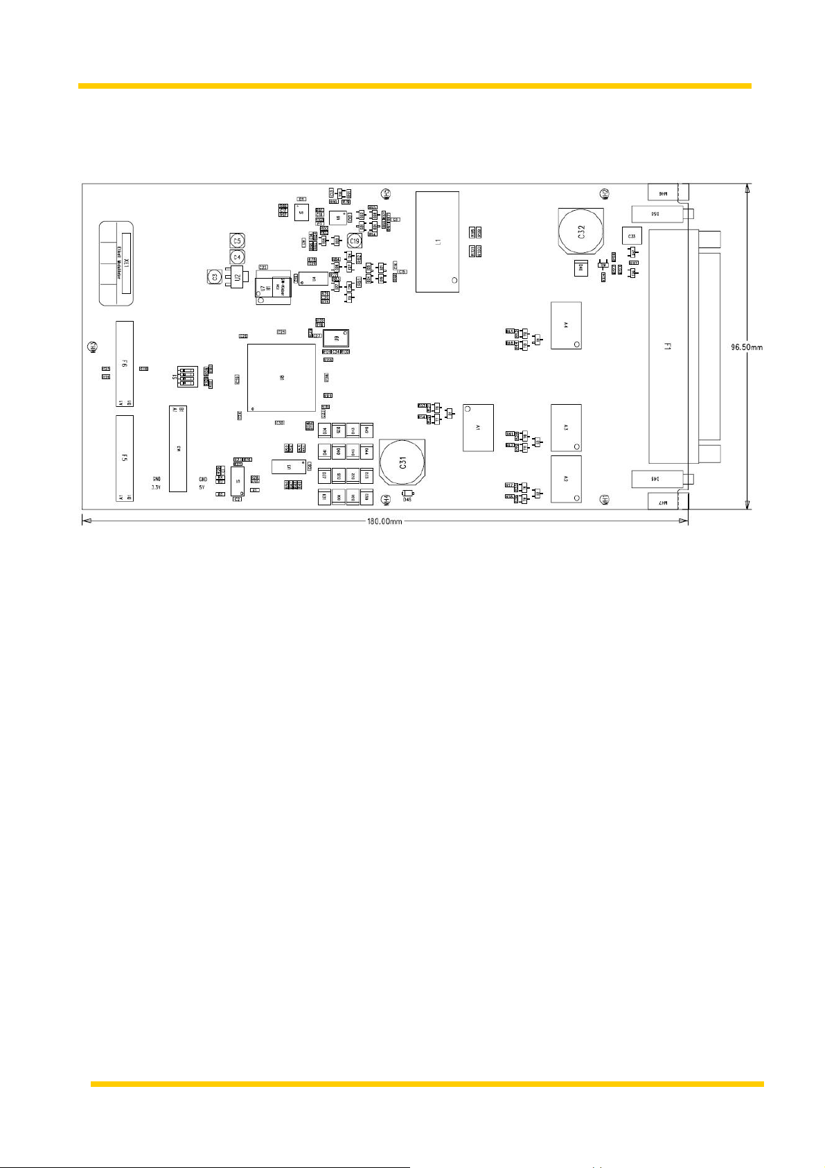
Dimensions: 183 x 96,5 x 50 (LxWxH) mm
17

I - SAD Modules
4.2 ISAD MI/O D-sub Modul
The I-SAD MI/O Module
handles up to 8 Inputs and 4 Outputs.
The MI/O D-sub consists of:
Connector
• 8 galvanically isolated inputs
• 4 parallel / bistabled potential-free outputs
• Only signals in the low power voltage range can be switched
(EN60950: SELV-circuit).
• Possibility to connect a Keytronix AlEx device (remote unit) via G.703
interface.
• 24V DC Output for feeding external equipment (max. 40mA)
All signals (Inputs and Outputs) are carried over one DB-37 connector
/ controlled loops
18

I - SAD Modules
Interface
pin assignment
Name
G.703
Input 1
Port 1
Output 1
Input 2
Port 2
Output 2
Input 3
Port 3
Output 3
Input 4
Port 4
Output 4
Port 5
Port 6
Port 7
Port 8
Input 5
Input 6
Input 7
Input 8
Power supply for external
Peripherie
Pin # Signal
17, 36 Transmit Data
18, 37 Received data
19, 35 GND
21
3
30
11
29
22
4
13
31
12
23
5
33
14
32
24
6
16
34
15
25
7
26
8
27
9
28
10
2
1, 20
Interrogation
GND
closed circuit contact
Common
Normally open
contact
Interrogation
GND
closed circuit contact
Common
Normally open
contact
Interrogation
GND
closed circuit contact
Common
Normally open
contact
Interrogation
GND
closed circuit contact
Common
Normally open
contact
Interrogation
GND
Interrogation
GND
Interrogation
GND
Interrogation
GND
+ 24V-Output
GND
19
I - SAD Modules
Common
open circuit
Input
Common
open circuit
l
okale
device (I
-
SAD)
remote device (AlEx)
G.703
-
Line
Application
Input
external
contact
Output
working contact
Output
1
supervisiory
2
supervisiory
6
7
8
Working contact
external
contact
20
I - SAD Modules
Common
open ci
rcuit
R2
Values of resistance for line supervisiory (sabotage monitoring) of
external contacts:
no sabotage,
sabotage,
short circuid
contact closed
no sabotage,
contact closed
Sabotage,
line interruption
<200 >300Ohm … <4kOhm >5kOhm … <9kOhm >20kOhm
Connection of the external contact for line supervisiory contact
external
contact
R1
R1 = >300 … <4kOhm
R1 +R2 = >5k … <9kOhm
Input
Output
working contact
1
supervisory
2
6
7
8
For prove working of line supervisory against sabotage, resistances R1 and
R2 has situated as near as possible at the external contact.
Notice that the line resistance to the external contact is arithmetic part of R1.
21
I - SAD Modules
Physical
Dimensions: 183 x 96,5 x 50 (LxWxH) mm
22

I - SAD Modules
4.3 I-SAD MCC Modul
The I – SAD MCC
(Modul Cabinet Control) is used for controlling cabinet doors.
Each modul is able to take control of two cabinet doors. By using
electromagnets the doors are permanently locked. If the current is switched
off, the doors are unlocked. An integrated sensor recognizes the position of
the door - opener (open / closed).
Connectors
There are also to Inputs for admission control sensors onboard.
All external peripherals can be connected over RJ12 connectors.
Only Rittal-made peripherals can be used.
Door - opener and door - contacts for remote control
4 x RJ 45 connector
23
 Loading...