

Page 1
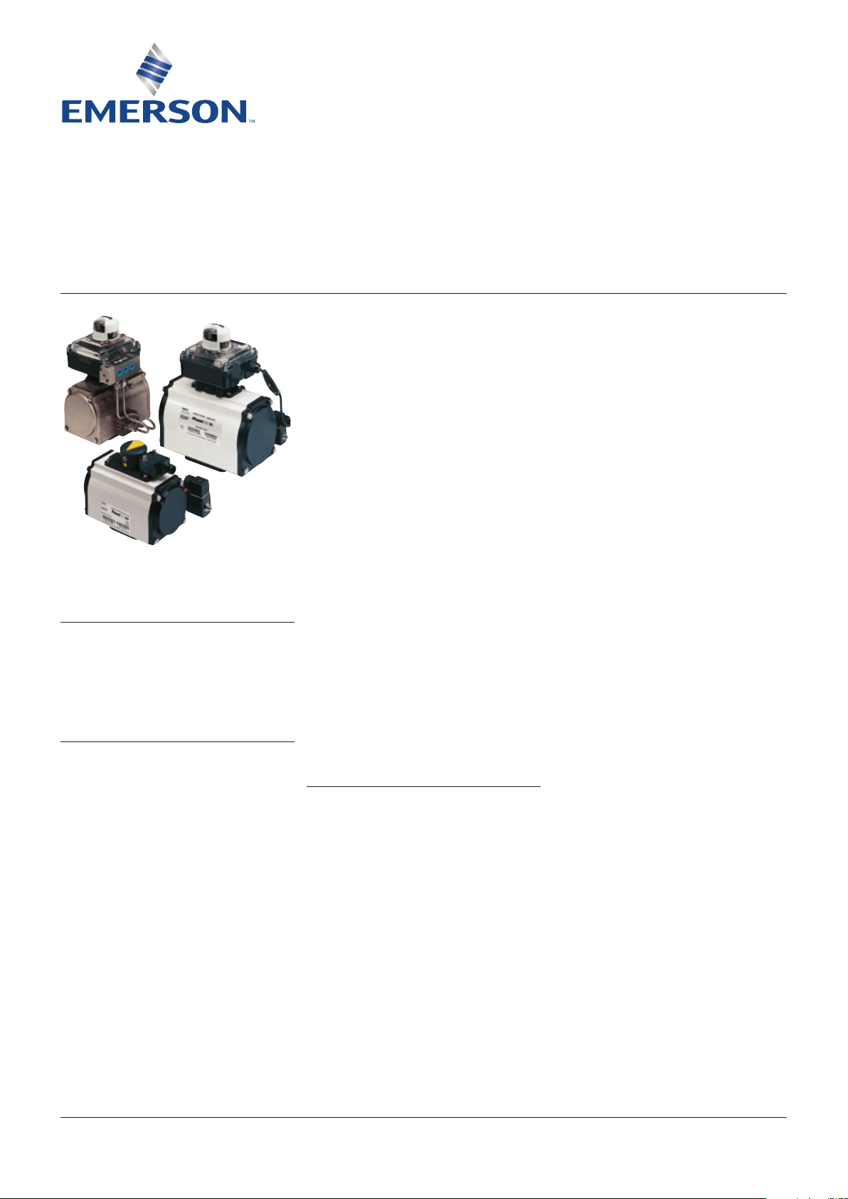
KEYSTONE PREMIAIR PNEUMATIC ACTUATOR
InstallatIon and maIntenance InstructIons
Before installation these instructions must be fully read and understood
DOUBLE ACTING AND SPRING RETURN
ACTUATORS ARE THE SAME SIZE
INTRODUCTION
The Keystone PremiAir Pneumatic Actuator is
a compact, rack and pinion design, conforming
to European and International standard
EN ISO5211 (preferred dimensions).
GENERAL PNEUMATIC SYSTEMS
RECOMMENDATIONS
All Keystone PremiAir Actuators are factory
lubricated with Molyrace LT2, which is a
molybdenum disulphide (MoS2) grease
and, unless the operating environment is
extremely harsh, do not require re-lubrication.
For applications where the environmental
temperature is between -40°C to -30°C,
AeroShell Grease 7 is specified.
To maintain maximum efficiency with this, or
other pneumatic actuators, we advise that the
following basic system recommendations are
followed:
1. Where air pipelines are subjected to
extremes of temperature, the system should
be fitted with suitable air drying equipment.
2. When working at low temperatures, it is
important that the compressed air has been
dried to a dew point of less than the ambient
temperature. If this is not the case, water
will be condensed from the compressed
air and freeze causing damage to the seals
inside the actuator, which could result in
actuator failure.
3. Air control lines should be fitted in
accordance with a ‘Recommended Piping
Practice’ and should not have loops, which
may trap condensate.
4. All air connection pipe ends should be
thoroughly cleaned and deburred after
cutting, to ensure that the pipeline is clear
of debris.
5. If pipelines are hydraulically tested, then
the lines should be 'blown down' with
pressurized air to clear all traces of water,
prior to connecting lines to the actuator.
6. Where pipe fitting sealants are used, they
should be applied to the male threads only,
to avoid excess compound being forced into
the actuator control lines.
7. Where Air Filter Equipment is used, the air
filters should be situated in positions that
allow easy access to maintain and/or drain.
8. Where pneumatic valve positioners, or
pneumatic controllers are fitted to valve
actuator assemblies, oil mist lubricated air
should not be used unless the manufacturer
states specifically that the controllers are
compatible with lubricated air.
Note: PremiAir actuators are rated for air
pressure in the range 2.75 barg (40 psig)
to 8.3 barg (120 psig) and will withstand a
maximum of 10.3 barg (150 psig).
CONSTRUCTION
PremiAir actuators are designed to be mounted
to quarter turn valves either directly or using
the correct mounting brackets/adaptors and
sizing procedures.
All models are of the opposed piston type. Each
piston incorporates an integral rack which
engages with a one piece drive pinion shaft. The
drive shaft is Nitrotech™ treated for maximum
protection and fitted with 'engineered polymer'
bearings. The actuator body is of extruded
aluminium, hard anodized and electrostatic
powder coated.
The design features bolt on mounting plate and
air connection plate for maximum adaptability.
O-rings are used for piston and shaft seals.
For Spring Return actuators, up to four springs
per piston can be fitted between the piston
head and end cap to suit the available operating
air pressure.
Adjustable travel stops are provided for each
end of travel to ensure that the actuator will
open and close the valve precisely.
The output drive is a female double square
(star), conforming to EN ISO5211.
NOTE
These instructions refer to all the range, except
size 180.
For Installation and Maintenance instructions relating
to size 180, please refer to document HDLDS-0012.
VCIOM-00036-EN 17/11Emerson.com/FinalControl © 2017 Emerson. All Rights Reserved.
Page 2

KEYSTONE PREMIAIR PNEUMATIC ACTUATOR
InstallatIon and maIntenance InstructIons
STANDARD INSTALLATION - DOUBLE AND
SINGLE ACTING UNITS
These instructions assume that the actuators
are installed with the cylinder axis parallel to
the axis of the valve bore (In Line) and are fitted
to Resilient Seated Butterfly Valves having
mounting pads conforming to EN ISO5211.
Single acting actuators are supplied as FAILCLOSE units as standard.
Reverse acting, (FAIL-OPEN), must be specified
at the time of order.
1. Ensure that the valve and actuator are in
the following corresponding positions:
•DoubleActingunitsandSpringReturn
units, (Fail-closed):
Valve closed, actuator fully clockwise.
•DoubleActingunitsandSpringReturn
units, (Fail-open):
Valve open, actuator fully counter-
clockwise
Mounting to ball and high performance
butterfly valves (via bracket)
2a. Secure the mounting bracket to the
underside of the actuator, using four bolts
and washers, as shown in Figure 1.
3a. Install the appropriate coupling onto the
valve stem. The coupling should be lightly
tapped or pressed onto the valve stem.
The use of a lubricant is recommended.
4a. Mount the actuator and bracket onto the
valve top flange using the appropriate bolts.
Mounting to resilient seated butterfly valves
(with EN ISO5211 mounting)
2b. Screw the actuator mounting studs tightly
into the actuator base plate.
3b. Mount the actuator onto the valve top flange
and secure using a lockwasher and nut on
each mounting stud.
All ¼ turn valve types
5. Before installing the valve/actuator
assembly in a piping system, the valve
operation should be verified and adjusted,
if necessary, using the travel stop screws
(see detailed instructions for travel setting)
6. When installing the valve/actuator assembly
into pipeline, ensure that the specific
instructions relating to the valve installation
are followed.
Note: some valves may require to be fitted
into the pipeline prior to mounting the
actuator.
Fail Safe butterfly valves are an example
of this.
NON STANDARD INSTALLATION - DOUBLE
AND SINGLE ACTING UNITS
All ¼ turn valve types
In circumstances where the actuator is
required to be installed in the transverse
position i.e. at right angles to the valve bore
(Across Line), the actuator must be rotated
through 90°.
This is achieved in the following manner:
1. Remove the actuator from the valve or the
bracket by removing the 4 fixing bolts/nuts
and withdraw it vertically from the valve.
2. Rotate the actuator through 90°.
3. Refit actuator to the top of the valve or to
the bracket. The output drive of the actuator
is a double square (star) design, with the
squares being at 90° to each other.
FIGURE 1
Typical installation on ball or high performance
butterfly valves, using bracket mounting
Actuator
Lockwasher
Bolt
Bolt
Coupling
if required
Bracket
if required
FIGURE 2
Typical installation on resilient seated butterfly
valves, with direct EN ISO5211 mounting
Lockwasher
Actuator
Stud
Nut
2
Page 3
KEYSTONE PREMIAIR PNEUMATIC ACTUATOR
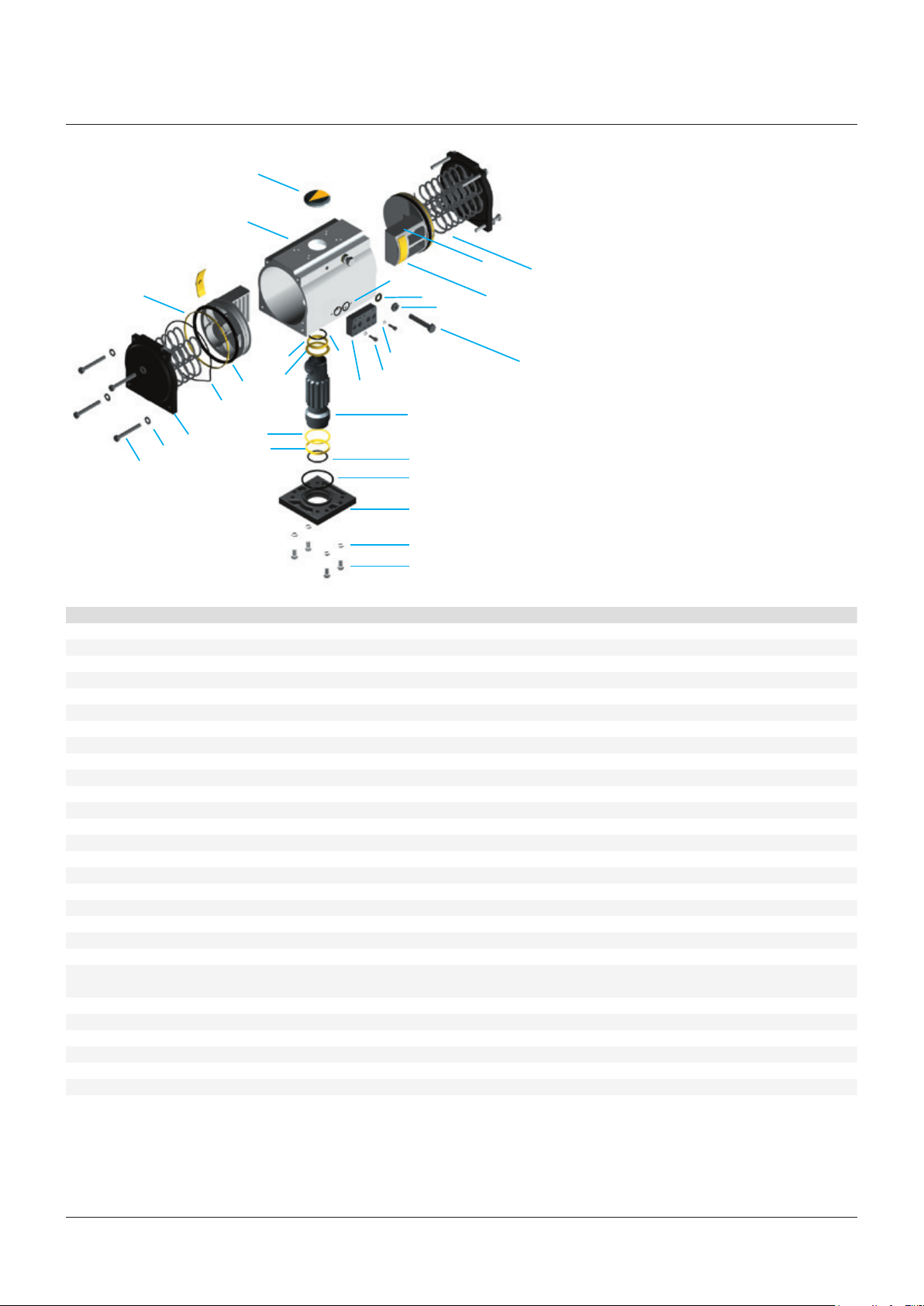
InstallatIon and maIntenance InstructIons - parts IdentIfIcatIon
23
1
8
9
11
24
25
2
17
16
12
10
26
29
15
14
21
20
6
4
27
28
5
19
18
3
7
22
13
MATERIALS OF CONSTRUCTION
Subject Item Material Finish
1 Body Extruded aluminium BS 1474 (6000 series) Hard Anodize + ESPC* or SNP**
2 End cap Die cast aluminium DIN1725 Alloy 231 Chromate + ESPC* or SNP**
3 Piston Die cast aluminium DIN1725 Alloy 231 Anodize or SNP**
4 Pinion shaft Carbon steel BS 1490:1983 212 A42 Nitrotech™*** or SNP**
5 Base plate Die cast aluminium DIN1725 Alloy 231 Chromate + ESPC* or SNP**
6 Air connection plate Aluminium DIN1725 Alloy 231 Chromate + ESPC* or SNP**
7 Piston backing pad Devlon-V™ Natural
8 Piston support ring Devlon-V™ Natural
9 Top bearing Devlon-V™ Natural
10 Bottom bearing Devlon-V™ Natural
11 Top spacer Devlon-V™ Natural
12 Bottom spacer Devlon-V™ Natural
13 Stop bolt Stainless steel A2 / 70 Natural
14 Lock nut Stainless steel A2 / 70 Natural
15 Sealing washer Stainless steel A2 / 70 Natural
16 End cap bolt Stainless steel A2 / 70 Natural
17 End cap washer Stainless steel A2 / 70 Natural
18 Base plate bolt Stainless steel A2 / 70 Natural
19 Base plate washer Stainless steel A2 / 70 Natural
20 Air connection plate bolt Stainless steel A2 / 70 Natural
21 Air connection plate washer Stainless steel A2 / 70 Natural
22 Spring Chrome silicon spring steel
BS 2806 685 A55 HD R2 Oil dip
23 Indicator ABS Natural
24 Piston O-ring Rubber-NBR or FPM Natural
25 End cap O-ring Rubber-NBR or FPM Natural
26 Shaft top O-ring Rubber-NBR or FPM Natural
27 Shaft bottom O-ring Rubber-NBR or FPM Natural
28 Base plate O-ring Rubber-NBR or FPM Natural
29 Air connection plate O-ring Rubber-NBR or FPM Natural
NOTES
* ESPC = Electrostatic powder coating
** SNP = Special nickel protection finish
*** Nitrotech™ = Roprietary corrosion resistant finish
3
Page 4

KEYSTONE PREMIAIR PNEUMATIC ACTUATOR
InstallatIon and maIntenance InstructIons
DISASSEMBLY PROCEDURE
CAUTION
Remove air pressure and observe normal safety
precautions, including the use of eye protection.
1. Remove travel stop bolts, (13) after
slackening the lock nuts.
2. Remove end caps (2) by unscrewing the four
hexagon head bolts on each end cap. For
spring return versions use the progressive
diagonal method for unscrewing these bolts.
3. Using a suitable wrench in the top of the
pinion shaft (4), turn the shaft counter
clockwise to drive the pistons (3) apart.
Remove the pistons from the body (1).
4. Remove the base plate (5) by unscrewing the
four cap head bolts and spring washers.
5. The pinion shaft (4) can now be withdrawn
from the bottom of the actuator body (1).
6. The top and bottom bearing rings, spacers
and O-rings can now be removed from the
pinion shaft or from the recesses in the body
and base plate.
7. The air connection plate (6) can be removed
from the body if necessary by unscrewing
the two cap head bolts.
8. Remove O-rings and support rings from the
piston heads.
9. Remove the backing pads from the piston
legs.
ASSEMBLY PROCEDURE (REFER TO FIGURE
ON PAGE 3)
1. Clean all disassembled items and replace
any damaged items such as O-rings,
bearings, support rings, and backing pads.
2. Grease the body bore with Molyrace LT2
lubricant.
3. Place the base plate (5) flat on the assembly
bench and fit the O-ring (28) into the groove
on the top face of the base plate.
4. Fit the bottom spacer (12), then the bottom
bearing (10), then the bottom O-ring (27)
over the bottom of the shaft and coat with
Molyrace LT2 lubricant.
5. Carefully insert the shaft along with the
spacer, bearing and O-ring into the base
plate bore, finishing with a firm push to
ensure full location.
6. Fit the top spacer (11), then the top
bearing (9), then the top O-ring (26) over the
top of the shaft and coat with Molyrace LT2
lubricant.
7. Carefully lower the body over the shaft and
on to the base plate, finishing with a firm
push to ensure that the O-ring and bearing
locate fully into the top recess of the body.
8. Secure the base plate to the body using
the cap head screws and spring washers
(18/19).
9. Grease the pinion shaft teeth with
MolyraceLT2 lubricant. Rotate the pinion
shaft until the keyways, in the shaft top,
are at 45 degrees as shown in the figure
(opposite 1).
10. Fit O-rings (24), support rings (8) and
backing pads (7) to the pistons and then
grease the rack teeth using Molyrace LT2
lubricant.
11. Insert the pistons into the actuator body as
follows:
a. Double acting and spring to close
models
With the piston rack on the left side of the
body bore, when viewed from the O-ring
end of the piston, as shown (opposite 2).
b. Spring to open models
With the piston rack on the right side
of the body bore, when viewed from the
O-ring end of the piston.
Locate the assembly on the bench with
one piston head on the bench and the
other upwards. Push firmly on the top
piston to cause both piston rack profiles
to engage with the pinion teeth.
1. Position of keyways prior to fitting pistons
2. Fitting pistons into body
3. Locating of springs in piston head cavities
4. Fitting air connection plate
2
4
4
Page 5

KEYSTONE PREMIAIR PNEUMATIC ACTUATOR
InstallatIon and maIntenance InstructIons
12. Position the assembly with the base plate
on the bench. Using a suitable wrench, turn
the pinion shaft clockwise (double acting
and spring to close models), or counterclockwise (spring to open), as far as it will
go. The keyways, at the top of the shaft,
should be approximately 4 to 5 degrees
clockwise, or counter-clockwise, past the
axial and transverse center lines of the
body.
13. Smear the O-ring groove in each end
cap with Molyrace LT2 lubricant. Fit the
O-rings (24) into the grooves and position
the actuator body with one end downwards
on the bench.
14. Double acting models
a. Carefully locate one end cap (2) on the
uppermost end of the body and secure
using four hexagon head bolts and plain
washers (16/17).
b. Repeat for the other end cap.
Spring return models
a. Locate the correct number of springs (22)
in the cavities on the piston head which is
uppermost. (See opposite 3)
b. Carefully locate one end cap over the
springs so that the springs fit into the
cavities in the end cap.
c. Using the four hexagon head bolts and
plain washers, compress the springs
following the diagonal progression
technique, until the end cap is fully
tightened down against the end of the
body.
d. Repeat for the other end cap.
15. Locate the O-rings (29) into the recesses
on the air connection plate and secure the
plate to the actuator body using the two
cap head bolts and spring washers (20/21).
Ensure that the port marked 'Port 2' is to
the right hand side as shown. (Opposite 4)
16. Fit the lock nuts and sealing washers (14/15)
to the travel stops and then screw the travel
stops into the body.
17. For double acting versions, ensure that the
pinion shaft is rotated fully clockwise and
then screw in the right hand travel stop until
the shaft keyways are in line with the major
axes of the body and then tighten the lock
nut to secure.
18. Turn the pinion shaft fully counter-clockwise
and then screw in the left hand travel stop,
until the shaft keyways are in line with the
major axes of the body. Tighten the locknut
to secure.
Note: for single acting versions, it is not
advisable to use the travel stop screws to
move the pinion as this may damage the
cam faces or the stop screw ends.
19. For single acting versions, screw in the left
hand travel stop to an estimated position
and then apply pressure to open the
actuator. Check the actual position of the
pinion shaft, release the air pressure and
re-set the travel stop to compensate for any
error. Repeat until the correct position is
achieved. Tighten the lock nut to secure.
20. Apply pressure to open the actuator and
screw in the right hand travel stop to an
estimated position and then release the
pressure. Check the actual position of the
pinion shaft. Re-apply the pressure and
re-set the travel stop to compensate for any
error. Repeat until the correct position is
achieved. Tighten the lock nut to secure.
SETTING OF INTERNAL TRAVEL STOPS
PremiAir actuators are fitted with integral end
of travel stops to enable setting of exact travel
for the valve being operated.
These stops allow travel adjustment, as follows:
Over Travel (at each end) of ±5°
Under Travel (at each end) of ±10°
Increased under travel is available, on request.
TO SET THE STOPS (DOUBLE ACTING UNITS)
1. Operate valve/actuator assembly to the
closed position.
2. Remove air supply.
3. Slacken locknut on the close travel stop.
4. Turn the stop clockwise to reduce travel or
anti-clockwise to increase travel.
5. Re-Tighten locknut.
6. Reconnect air supply and check that the
position is correct. If not repeat from
instruction 2.
7. Apply air to operate to the open position.
8. Remove air supply.
9. Adjust open travel stop screw as per
instructions 3 to 6, above.
5
Page 6

KEYSTONE PREMIAIR PNEUMATIC ACTUATOR
InstallatIon and maIntenance InstructIons
TO SET THE STOPS (SINGLE ACTING UNITS)
AIR FAIL CLOSE
1. Remove air supply so that actuator drives to
closed position. Note actual position.
2. Apply air to open the actuator. Note actual
position.
3. Whilst the air supply is maintained slacken
the locknut on the close stop and adjust
the stop screw by an amount estimated to
give correct position. (clockwise adjustment
decreases travel).
4. Re-tighten lock nut.
5. Remove air so that actuator closes. If
correct closed position is not achieved
repeat from instruction 2.
6. Slacken locknut on the open stop and adjust
the travel by an amount estimated to give
correct position. (clockwise adjustment
decreases travel).
7. Re-tighten locknut.
8. Apply air and check open position. If correct
open position is not achieved, repeat from
instruction 5.
TO SET THE STOPS (SINGLE ACTING UNITS)
AIR FAIL OPEN
1. Remove air supply so that actuator drives to
open position. Note actual position.
2. Apply air to close the actuator. Note actual
position.
3. Whilst the air supply is maintained slacken
the locknut on the open stop and adjust the
stop screw by an amount estimated to give
correct position. (clockwise adjustment
decreases travel).
4. Re-tighten lock nut.
5. Remove air so that actuator opens. If correct
open position is not achieved repeat from
instruction 2.
6. Slacken locknut on the close stop and adjust
the travel by an amount estimated to give
correct position. (clockwise adjustment
decreases travel).
7. Re-tighten locknut.
8. Apply air and check close position. If correct
close position is not achieved, repeat from
instruction 5.
WARNING
Under no circumstances must the travel stop
bolts be totally withdrawn from the actuator whilst
compressed air is being applied.
Travel stop bolts must not be used for manual
override.
Accessories mounted to the top of Actuators must
be re-adjusted accordingly after setting the travel
stops.
MAINTENANCE
Provided that basic pneumatic system
procedures are adhered to, the actuator will
require little or no maintenance for many
thousands of cycles.
TROUBLESHOOTING
If the actuator fails to operate the valve
correctly, carry out the following checks.
1. Check that the air supply is at the required
pressure.
2. Ensure that the air supply is not restricted in
any way.
3. Check for air leakage on supply lines to the
actuator.
4. Check for leakage at the top and bottom
of the pinion shaft. Such leakage could be
caused by a dirty air supply.
5. Check for leakage across the piston seals by
applying pressure to 'Port 4' and looking for
leakage from 'Port 2'.
6. Check that the valve torque has not
increased because of problems with the
valve itself.
Note: refer to disassembly and assembly
procedures for gaining access to O-rings
and actuator internals if required.
GENERAL INFORMATION
1. As standard, applying air to 'Port 2' will
cause the actuator to rotate in a counter
clockwise direction to open the valve.
2. Applying air to 'Port 4' will cause the
actuator to rotate in a clockwise direction to
close the valve (double acting versions only).
3. Warning: it is not recommended to 'air
assist' single acting actuators as this may
apply excess load to the valve stem and
cause damage.
Spring ratings versus air pressure
There is one size of spring per actuator for
‘balance’ against air pressures up to 80psig
(5.5barg).
Springs are used in multiples depending on the
air pressure.
The following table shows the springs needed
to give balance at varying air pressures.
‘Balance’ means that air start torque = spring
start torque...
and that air finish torque = spring finish torque.
Number of springs
Air pressure
40psig / 2.8barg 2 2
50psig / 3.5barg 3 2
60psig / 4.2barg 3 3
70psig / 4.8barg 4 3
80psig / 5.5barg 4 4
Piston 1 Piston 2
For balance against higher pressures booster
springs are fitted inside the standard springs of
the 80psig build as follows.
Number of booster springs
Air pressure
90psig / 6.2barg 2 2
100psig / 6.9barg 4 4
Piston 1 Piston 2
6
Page 7

KEYSTONE PREMIAIR PNEUMATIC ACTUATOR
InstallatIon and maIntenance InstructIons
BOLT TIGHTENING TORQUES FOR END CAPS
When re-assembling the end caps, use the following figures for bolt tightening.
Actuator size Bolt size Tightening torque (Nm)
-002 M5 3.2
-004 M5 3.2
-009 M6 7.3
-014 M6 7.3
-025 M8 13.1
-037 M8 13.1
-045 M10 26.2
-070 M12 45.2
-088 M12 45.2
-180 M16 108.5
Neither Emerson, Emerson Automation Solutions, nor any of their affiliated entities assumes responsibility for the selection, use or maintenance of any product.
Responsibility for proper selection, use, and maintenance of any product remains solely with the purchaser and end user.
Keystone is a mark owned by one of the companies in the Emerson Automation Solutions business unit of Emerson Electric Co. Emerson Automation Solutions, Emerson
and the Emerson logo are trademarks and service marks of Emerson Electric Co. All other marks are the property of their respective owners.
The contents of this publication are presented for informational purposes only, and while every effort has been made to ensure their accuracy, they are not to be
construed as warranties or guarantees, express or implied, regarding the products or services described herein or their use or applicability. All sales are governed by
our terms and conditions, which are available upon request. We reserve the right to modify or improve the designs or specifications of such products at any time without
notice.
Emerson.com/FinalControl
7
 Loading...