

KEYSTONE FIGURE 627PQ BUTTERFLY VALVE
INSTALLATION, MAINTENANCE AND ADJUSTMENT INSTRUCTIONS
Before installation these instructions must be read fully and understood
1 STORAGE AND HANDLING
1.1 Protection
HP butterfly valves are delivered with
protection in accordance with the Engineering
Instructions, to protect the valve seats and disc
from damage. Wrapping and/or covers should
be left in place until immediately before fitting
to the pipe.
1.2 Storage
When valves are to be stored for some time
before being fitted, storage should be in the
original delivery crates or cases. Storage
should be off the ground in a clean, dry indoor
area.
1.3 Handling
1.3.1 Packed valves
The lifting and the handling of the packed
valves in crates should be carried out by
appropriate lifting equipment. If a fork lift truck
is used, appropriate fork hitches are required.
The lifting and handling of packed valves in
cases will be carried out in the lifting points.
The transportation of all packed material
should be carried out safely and according to
the local safety regulation.
1.3.2 Unpacked valves
The lifting and the handling of these valves have
to be carried out by using appropriate means
and by respecting the carrying limits. The
handling must, preferably, be carried out on
pallets, protecting the machined surfaces and
seat to avoid damage.
When lifting the large dimension valves, the
sling and the hooking of the load must be
carried out by using the appropriate tools
(brackets, hook, fasteners) and load balancing
tools in order to prevent the valves from falling
or moving during the lifting and handling.
The valve may be lifted only by slings attached
to the flange holes or valve body; never to the
actuator or the valve opening.
2 INSTALLATION
WARNING
For safety reasons, it is important to take the
following precautions before you start work on
the valve:
1. Personnel making any adjustments to the
valves should utilize suitable equipment. All
required personal protection means should be
worn.
2. The line must be depressurized before
installing the valve.
3. Personnel trained in all aspects of manual and
mechanical handling techniques may carry out
handling of the valves.
4. Misuse of the valve is not allowed. For
example: the valve, handles, actuators or
other parts may not be used as “climbing
tools”.
5. Ensure that valve pressure /temperature
limitations marked on the identification tag are
within the service conditions.
6. Ensure that valve materials are compatible
with the pipeline fluid
2.1 Valve inspection
1. Carefully remove the valve from the
shipping package (box or pallet) avoiding any
damage to the valve or, in case of automated
valves, to the electric or pneumatic/
hydraulic actuator or instrumentation.
2. Confirm that the materials of construction
listed on the valve nameplate are
appropriate for the service intended and are
as specified.
3. It is not allowed to use third party spare
parts. In case of third party spare parts, safe
operation is not guaranteed.
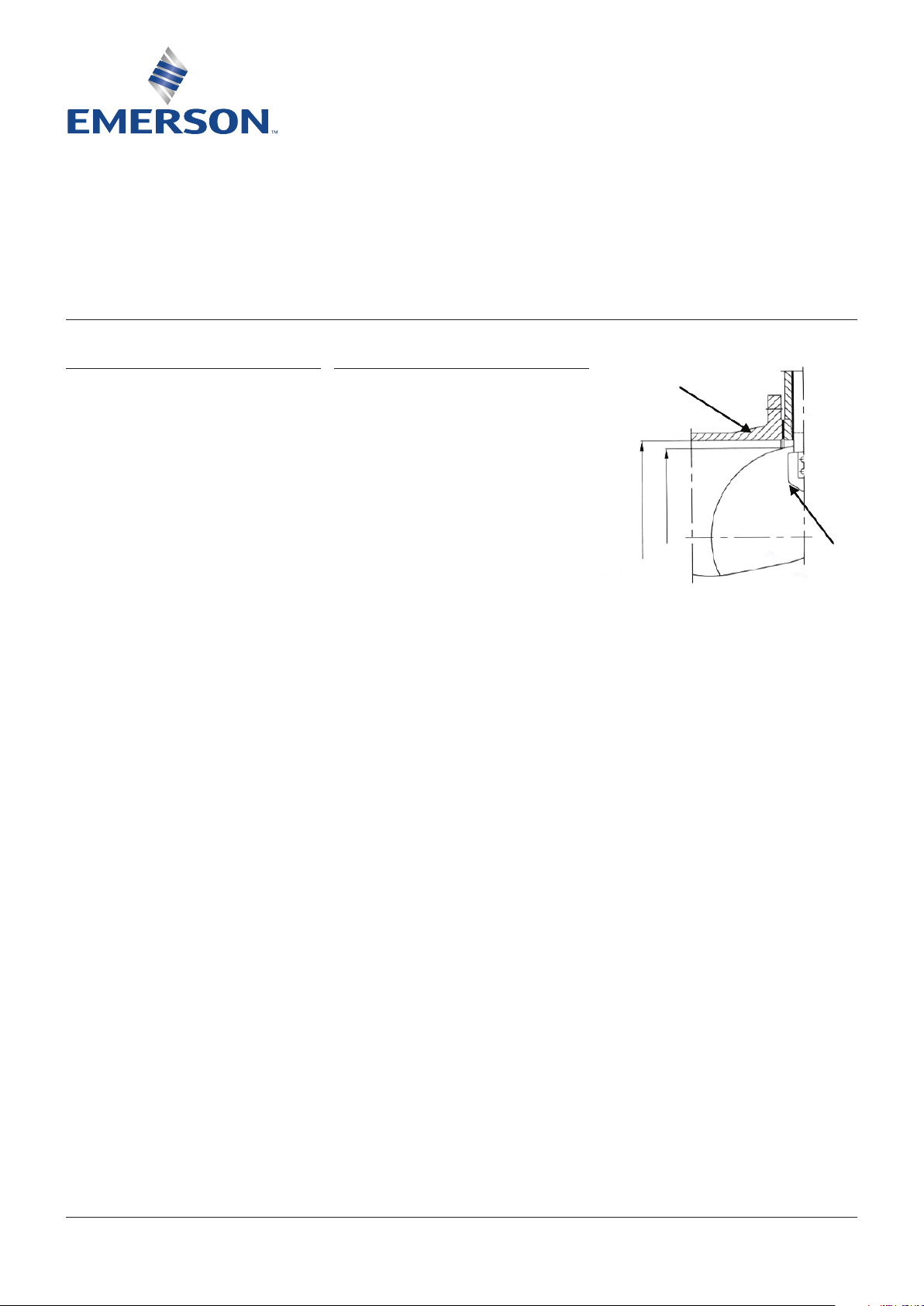
2.2 Flange and pipe compatibility
Check matching of flange drilling pattern of
valve and pipe before assembly.
Flanges have to meet the following
requirements:
-The face inside diameter should be:
D min.: The valve J-dimension plus adequate
disc clearance.
D max.: The inside diameter (ID) of standard
pipe before assembly.
Pipline
J
D max/ min
Valve application to be within the pressure/
temperature limits indicated in the P/T diagram.
Essential points and functions of the valve
should be inspected on a regular basis.
Disc
Emerson.com/FinalControl
© 2019 Emerson. All Rights Reserved.
VCIOM-14782-EN 19/11

KEYSTONE FIGURE 627PQ BUTTERFLY VALVE
INSTALLATION, MAINTENANCE AND ADJUSTMENT INSTRUCTIONS
2.3 Valve Installation
1. Handling and lifting of the valves during
installation must be performed following
the same instructions described in previous
paragraph “1.3 Handling”.
2. Valve is not a support stand. Do not use it as
a support part of the pipe line construction.
3. While butterfly valves are not used, valve
disc shall be opened slightly (4° - 5°)
to guarantee that the sealing surfaces
will not be damage during storage and
transportation.
4. When welding connecting flanges onto pipe,
butterfly valve shall not be put between
these being weld parts in case the principal
and auxiliary sealing rings are burnt.
5. Before butterfly valve is installed, foreign
materials shall be rinsed out of pipeline.
6. For optimum valve control and smooth
performance, it is recommended to have
a straight pipe with 10 to 20 times of valve
DN for running inlet flow and a straight pipe
with 3 to 5 times of valve DN for running
outlet flow.
7. While installing butterfly valve, make sure
the centerline of the valve coincides with
that of the pipeline in case that the disc can
not be opened and will touch pipeline wall
and damage sealing surfaces.
8. Valve shall be installed according to the
water flow direction. On special occasions,
please contact factory technology
department.
9. After the valve installing is finished and
before it is open to water, the valve shall be
opened and pipeline shall be rinsed with
maximum flow repeatedly in case weld slag
or other foreign things are left in pipeline
and damage the sealing surfaces.
10. It is not permitted to let hot weld slag drop
to sealing parts of valve. While installing
a butterfly valve crosswise (the valve
centerline is perpendicular to horizontal
plane), the valve shall be completely opened.
11. Because dry friction can cause quality
variation of rubber seal, to prolong the life
span of valve, if there is no water in pipeline,
please do not close the valve.
12. For valves from DN 350 through DN 1400,
worm gear box and driving shaft of valve
are linked by key. While mounting worm
gear box to valve, take care to guarantee its
correct mounting position.
13. Adjacent piping must be positioned so that
minimal piping stresses are transmitted to
the flanges during or after installation.
NOTES
The valve can be installed in the pipe-line either with
or without the actuator mounted on top of the valve.
Make sure that you can turn the disc cautiously so you
can feel a mismatch resulting from a disc touching of
the adjacent piping.
Handling and lifting of the valve during installation
MUST be performed following the same instructions
described in previous paragraph “1.3 Handling”.
IMPORTANT
Mating flange faces should be in good condition
and free of dirt and/or inclusions. Both pipe
insides shall be well cleaned.
2.3.1 Installation
1. Check whether the distance of facing
pipe flanges meets the valve face-to-face
dimensions. Spread with adequate tooling
the flanges for easy insertion of the valve.
2. Insert some flange bolts in the pipe flanges,
to help you bear the valve after insertion.
3. Close the valve so far, that the disc-edge is
at least 10mm within the body.
4. Insert the valve between the flanges, center
the valve body and insert all flange bolts.
Tighten the flange-bolts tight by hand.
5. Slowly open the valve completely. (The disc
is in line with keyway in stem head.)
6. Maintain the valve flange alignment while
gradually removing the flange-spreads and
tighten the flange-bolts tight by hand.
7. Slowly close and open the valve to check for
adequate disc clearance.
8. Cross-tighten all bolting to the proper
torque. Do not over tighten.
2
 Loading...