

Keystone Manuals: Electric Actuators model EPI-2 OM1 Modulating I/O Module IOM, Keystone-EN Manuals & Guides

Installation, Operation and Maintenance Manual
Keystone OM1 - EPI2
Modulating Input/Output Module
VCIOM-01494-EN Rev. 0
June 2022

Notes
June 2022
Installation, Operation and Maintenance Manual
VCIOM-01494-EN Rev. 0
This page intentionally left blank

Installation, Operation and Maintenance Manual
VCIOM-01494-EN Rev. 0
Table of Contents
Section 1: Optional Module 1: Modulating I/O Module
1.1 OM1 Module Functionality ......................................................................... 1
1.2 Manufacturer ............................................................................................. 2
Section 2: Installation
2.1 Assembling Procedure for Models 63-125 Nm
Old Version (US or Non-US Market) ............................................................. 4
2.2 Assembling Procedure for Models 250-500-1000-2000 Nm
Old Version (US or Non-US Market) ............................................................. 7
2.3 Assembling Procedure for Models 63-125 Nm
New Version (US or Non-US Market) ............................................................ 9
2.4 Assembling Procedure for Models 250-500-1000-2000 Nm
New Version (US or Non-US Market) ........................................................... 12
Table of Contents
June 2022
Section 3: OM1 Module Setting and Conguration
3.1 Local Setting of OM1 ................................................................................... 15
3.1.1 OM1 Module Default General Setting ............................................... 15
3.1.2 OM1 Module Setting ........................................................................ 15
3.1.3 4 - 20 mA/0 - 10 V DC Input Setting ................................................. 18
3.1.4 4 - 20 mA/0 - 10 V DC Output setting .............................................. 18
3.1.5 Relays AUXC1, AUXC2, AUXC3 and AUXC4 Settings ......................... 19
3.1.6 Dead Band Settings .......................................................................... 21
3.1.7 Position Request .............................................................................. 21
3.2 Additional Bluetooth Optional Card ............................................................ 21
Section 4: Monitor Relay Functionality and Setting
Monitor Relay Functionality and Setting ............................................................... 22
Section 5: OM1 Kits
OM1 Kits .............................................................................................................. 23
Section 6: OM1 Wiring Diagram
OM1 Wiring Diagram ........................................................................................... 27
Table of Contents
i

Notes
June 2022
Installation, Operation and Maintenance Manual
VCIOM-01494-EN Rev. 0
This page intentionally left blank

Installation, Operation and Maintenance Manual
VCIOM-01494-EN Rev. 0
NOTE:
Before installation, these instructions must be fully read and understood.
Section 1: Optional Module 1: Modulating I/O Module
Section 1: Optional Module 1:
Modulating I/O Module
1.1 OM1 Module Functionality
The OM1 Modulating I/O module is supplied as an option on Keystone EPI2 actuators.
It is possible to receive the actuator already equipped with the OM1, ordering it with
the basic feature.
Alternatively, it is possible to order the OM1 as a separate kit and install it in the basic
actuator in the factory or in the field.
The OM1 is an optional module suitable to accomplish the following EPI2 actuator
additional functionalities:
June 2022
• Positioner with analog position input 4 - 20 mA or 0 - 10 V DC optocoupled
• Analog output position transmitter 4 - 20 mA or 0 - 10 V DC optocoupled
• Monitor relay remote indication for:
— loss of power
— stop by torque out of limit
— direction failure
— over-temperature
— position sensor alarm
— valve jammed
— hardware malfunction
— alarm on local control panel (if present)
— stroke failure
• Blinker/Local selector relay remote indication
• 4 additional SPST output contacts to be set independently at 12.5% intervals along
the stroke. Contacts are congurable (make or break)
• Optional Bluetooth connection feature
NOTE:
For decommissioning instructions, please refer to the relevant section in the EPI2 manual
ref. VCIOM-15516-EN.
Optional Module 1: Modulating I/O Module
1

Section 1: Optional Module 1: Modulating I/O Module
June 2022
WARNING
!
EPI2 actuator must be electrically isolated before any disassembling or reassembling
operations. Before any disassembling or reassembling operations, please follow in
detail the relevant paragraph of the basic installation and operating manual (latest
revision available).
WARNING
!
The electronic parts of the EPI2 actuators and all option modules can be damaged by
a discharge of static electricity. Before you start, touch a grounded metal surface to
discharge any static electricity.
WARNING
!
It is assumed that the installation, conguration, commissioning, maintenance, and repair
works are carried out by qualied personnel and checked by responsible specialists.
Installation, Operation and Maintenance Manual
VCIOM-01494-EN Rev. 0
WARNING
!
Repair work, other than operations outlined in this manual, is strictly reserved to qualied
Keystone personnel or to personnel authorized by the company itself.
1.2 Manufacturer
Manufacturer with respect to Machinery Directive 98/37: as specied on the motor label.
2
Optional Module 1: Modulating I/O Module

Installation, Operation and Maintenance Manual
VCIOM-01494-EN Rev. 0
Section 2: Installation
To assemble the OM1 into the EPI2 actuator, proceed as follows:
• Ensure that all the parts received with the OM1 are available as described in
Section 5.
• Using Section 5, select only mechanical parts (screws and spacers) depending on
actuator models.
• Gather the right tools for the assembly and for setting the actuator controls.
• With an Allen wrench of 5 mm, unscrew the cover screws as shown in Figure 1.
• Remove the actuator cover as shown in Figure 2.
Figure 1
Section 2: Installation
June 2022
Figure 2
Follow one of the following assembling procedures depending on actuator model.
Installation
3
Section 2: Installation
June 2022
Installation, Operation and Maintenance Manual
VCIOM-01494-EN Rev. 0
2.1 Assembling Procedure for Models 63-125 Nm
Old Version (US or Non US Market)
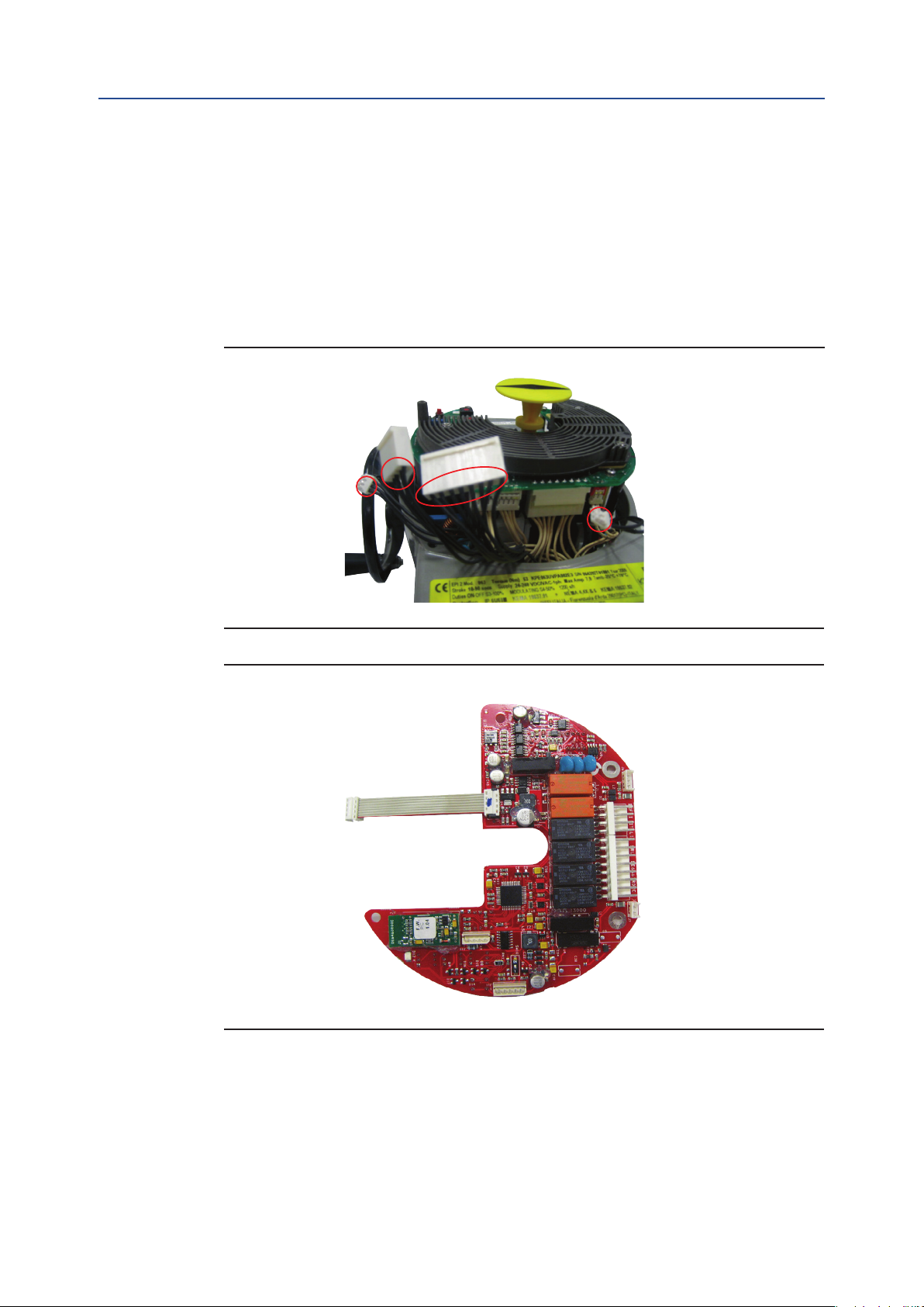
• Detect the 4 black cables required for the OM1 which are already included in the
basic actuator as shown in Figure 3.
• Connect the at cable furnished into the kit to connector J9 on OM1 as shown in
Figure 4.
Figure 3
Figure 4
• Unscrew the 3 screws as shown in Figure 5:
— 3 pcs M3x10
• Tighten the 3 metal spacers as shown in Figure 6.
4
Installation

Installation, Operation and Maintenance Manual
VCIOM-01494-EN Rev. 0
Figure 5
Figure 6
Section 2: Installation
June 2022
screw
metal spacer
• In Figure 7, connect OM1 at cable to connector J8 on the logic board.
• In Figure 8, place the OM1 card onto the spacer and tighten the 4 screws.
Figure 7
Installation
5

Section 2: Installation
June 2022
Figure 8
• Connect the following connector as shown in Figure 9:
Installation, Operation and Maintenance Manual
VCIOM-01494-EN Rev. 0
screw
— the 8-pin connector to connector J3 on OM1
— the 4-pin connector to connector J2 on OM1
— the 3-pin connector to connector J6 on OM1
— the 2-pin connector to connector J7 on OM1
Figure 9
6
Installation
 Loading...