


Keystone EPI2
Electric Actuator
Installation, Operation and Maintenance Manual
MAN-10-04-100-0711-EN Rev. 0
October 2020

Notes
October 2020
Installation, Operation and Maintenance Manual
MAN-10-04-100-0711-EN Rev. 0
This page intentionally left blank

Installation, Operation and Maintenance Manual
MAN-10-04-100-0711-EN Rev. 0
Table of Contents
Section 1: General Safety Instructions
1.1 Intended Use ............................................................................................... 1
1.2 Terms and Conditions ................................................................................. 2
1.3 Manufacturer's Liability ............................................................................... 2
1.4 Identication .............................................................................................. 3
1.4.1 Water - Dust-Proof Version ............................................................... 3
1.4.2 Explosion-Proof Version .................................................................... 4
1.5 Applicable Standards And Regulations ........................................................ 6
1.6 Extract From The Standard .......................................................................... 6
1.7 Manufacturer .............................................................................................. 6
Section 2: Machine Description
2.1 General ....................................................................................................... 7
2.2 Principle of Operation ................................................................................. 7
2.3 Electrical Operation .................................................................................... 7
2.4 Manual Operation ....................................................................................... 8
2.5 Description of the Main Parts ...................................................................... 8
2.6 Optional Modules ....................................................................................... 9
2.7 Options Label ............................................................................................ 10
Table of Contents
October 2020
Section 3: Storage and Pre-Installation
3.1 Checks to be Carried Out when the Actuator is Received ........................... 11
3.2 Storage Procedure .................................................................................... 11
3.2.1 General........................................................................................... 11
3.2.2 Storage for a Brief Period (less than one year) ................................. 12
3.2.3 Long Period Storage (more than one year) ...................................... 12
Section 4: Installation
4.1 Checks to be Performed Before Installation ............................................... 13
4.2 Working Condition.................................................................................... 13
4.3 Coupling Block .......................................................................................... 14
4.4 Installation of the Keystone EPI2 Unit Onto a Valve .................................... 15
4.5 Manual Operation ..................................................................................... 15
4.6 Setting Of The Angular Stroke: Mechanical Stops ...................................... 16
4.7 Electrical Connections ............................................................................... 17
4.8 Plant Requirements ...................................................................................17
4.9 Removal of the Terminal Board Enclosure .................................................. 19
4.10 Cables Connections .................................................................................. 20
4.11 Base Wiring Diagram ................................................................................ 22
4.12 Cable entries ............................................................................................. 23
4.13 Safety Instructions for Installation in Hazardous Area ................................ 24
4.13.1 Instructions for Explosion-Proof Enclosures .................................... 24
Table of Contents
I

Table of Contents
October 2020
Section 5: Lubrication
Section 6: Actuator Conguration
Installation, Operation and Maintenance Manual
MAN-10-04-100-0711-EN Rev. 0
5.1 Lubrication Inspection .............................................................................. 26
6.1 Removal of the Control Unit Cover ............................................................ 28
6.2 Local Conguration of the Keystone EPI2 .................................................. 29
6.2.1 Keystone EPI2 Default General Conguration.................................. 29
6.2.2 Close Limit Conguration by Position.............................................. 31
6.2.3 Close Limit Conguration ............................................................... 31
6.2.4 Open Limit Conguration by Position ............................................. 31
6.2.5 Open Limit Conguration ............................................................... 32
6.2.6 Close Limit Conguration by Torque ............................................... 32
6.2.7 Open Limit Conguration by Torque ............................................... 32
6.2.8 Stroking Time Selection in Closing .................................................. 33
6.2.9 Stroking Time Selection in Opening ................................................ 34
6.2.10 Setting of the Torque Limiting Device in Closing ............................. 34
6.2.11 Conguration of the Torque Limiting Device in Opening ................. 35
6.2.12 Reverse Mode Conguration .......................................................... 35
6.2.13 Actuator Model Selection ............................................................... 36
6.2.14 Blinker / Local Selector Conguration ............................................. 37
6.2.15 3-WIRES/2-WIRES Remote Control Conguration ........................... 38
6.3 Conguration of the Keystone EPI2 by a PDA / PC
and ‘A Manager’ Software ......................................................................... 38
6.4 Hardware Conguration for Monitor Relay ................................................ 39
Section 7: Maintenance and Troubleshooting
7.1 Maintenance ............................................................................................. 40
7.1.1 Routine Maintenance ...................................................................... 40
7.1.2 Special Maintenance ....................................................................... 40
7.2 Trouble-Shooting ...................................................................................... 41
7.2.1 The Electronics do not Switch on When Powered ............................ 41
7.2.2 24 V DC Output Voltage not available at the Terminals ................... 41
7.2.3 The Actuator does not work from Remote Controls ........................ 42
7.2.4 The motor is Very Hot and does not Start ........................................ 42
7.2.5 The Motor Runs but the Actuator does not Move the Valve ............. 42
7.2.6 The Valve does not Seat Correctly ................................................... 42
7.2.7 Excessive Torque for Valve Operation .............................................. 43
7.2.8 The Actuator does not Stop in Fully Open or Fully Closed Position ... 43
7.2.9 Diagnostic Led ................................................................................ 43
Section 8: Decommissioning
8.1 Disposal and Recycling .............................................................................. 44
Section 9: Parts List and Drawings
Parts Lists and Drawings ............................................................................ 45
II
Table of Contents

Installation, Operation and Maintenance Manual
MAN-10-04-100-0711-EN Rev. 0
Section 1: General Safety Instructions
Section 1: General Safety Instructions
1.1 Intended Use
The Keystone EPI2 electric actuators covered in this Instruction and Operating Manual are
designed for the operation of any kind of quarter-turn industrial valves (ie., ball, buttery,
plug and control valves) used in a wide range of applications ranging from heavy
industrial, chemical, petrochemical plants, waterworks, water pipelines, waste paper
plants and power plants to food, brewing and heating, ventilation, air conditioning, etc.
Emerson Valves & Controls will not be liable for any possible damage or physical injury
resulting from use in other than the designated applications or by lack of care during
installation, operation, adjustment and maintenance of the machine. Such risks lie
entirely with the user. Depending on the specic working conditions, additional
precautions may be requested. Considering that Emerson has no direct control over
particular applications, operation or maintenance conditions, it is the operator's
responsibility to comply with all applicable safety rules.
October 2020
Please inform Emerson urgently if you face unsafe situations not described in this IOM.
It is the sole responsibility of the operator to ensure that the local health and safety
regulations are adhered to. Keystone EPI2 are tested according to EN 21680. Noise level is
less than 65 dB (grade A) at 1 m distance.
WARNING
!
It is assumed that the installation, conguration, commissioning, maintenance and repair
works are carried out by qualied personnel and checked by responsible specialists.
WARNING
!
Any repair work, other than the operations ou/Uned in this manual, is strictly reserved to
qualied Emerson personnel or to personnel directly authorized by the company itself.
General Safety Instructions
1

Section 1: General Safety Instructions
October 2020
Keystone EPI2 electric actuators are designed in accordance with the applicable
international rules and specications, but the following regulations must be observed in
any case:
• The general and safety regulations
• The plant specic regulations and requirements
• The proper use of personal and protective devices (glasses, clothing, gloves, etc.)
• The proper use of tools, lifting and transport equipment
• Electrical installation, use and maintenance on Keystone EPI2 has to be carried out
in accordance with the National Legislation and statutory requirement related to
the safe use of Keystone EPI2 actuators, applicable to the site of installation
• Should further information and guidance related to the safe use of Keystone EPI2
actuators is requested, please contact Emerson
WARNING
!
The electronic parts of the Keystone EPI2 and all the optional modules can be damaged
by a discharge of static electricity. Before you start, touch a grounded metal surface to
discharge any static electricity.
Installation, Operation and Maintenance Manual
MAN-10-04-100-0711-EN Rev. 0
1.2 Terms and Conditions
Emerson guarantees each single product to be free from defects and to conform to
current goods specications. The warranty period is one year from the date of installation
by the rst user, or eighteen months from the date of shipment to the rst user,
whichever occurs rst.
No warranty is given for products which have been subject to improper storage, improper
installation, misuse, or corrosion, or which have been modied or repaired by unauthorized
personnel. Repair work due to improper use will be charged at standard rates.
1.3 Manufacturer's Liability
Emerson declines all liability in the event of:
• Use of the actuator in contravention of local safety at work legislation
• Incorrect installation, disregard or incorrect application of the instructions
provided on the actuator nameplate and in this manual
• Modications without Emerson's authorization
• Work done on the unit by unqualied or unsuitable persons
2
General Safety Instructions

Installation, Operation and Maintenance Manual
MAN-10-04-100-0711-EN Rev. 0
1.4 Identication
1.4.1 Water - Dust-Proof Version
Keystone EPI2 actuators are designed and manufactured according to EN 60529 standards.
Specic types of protection are printed on the label, as follows:
• IP66/68
• NEMA 4/4X/6 according to NEMA ICS6 / NEMA 250
Figure 1 Label for Application in Water - Dust-Proof Areas
Section 1: General Safety Instructions
October 2020
A. Manufacturer logo
B. Product model
C. Nominal output torque value
D. Product code
E. Serial number
F. Stroking time range
G. Power supply data
H. Max current absorption in ampere
I. Environmental data
L. Actuator duties
M. Weather-proof protection degree (EU and US)
N. Weather-proof certicate reference (EU and US)
O. Manufacturer details
P. Year of construction
General Safety Instructions
3

Section 1: General Safety Instructions
October 2020
1.4.2 Explosion-Proof Version
The version of Keystone EPI2 suitable for installation in hazardous areas is designed and
manufactured according to EN 60079-0, EN 60079-1, EN IEC 60079-7, EN 60079-31 standards.
Different types of protection are available, depending on the requirements of the
installation site.
The driven valve or associated gear reducer will form part of a separate risk analysis according
to Directive 2014/34/EU and following the EN ISO 80079-36 and EN ISO 80079-37 norms.
Specic types of protection are printed on the label, as follows:
• ATEX Ex de IIB T5 with enclosures in ‘explosionproof’ version and terminal board
enclosure in ‘increased safety’ version
• FM rated as ameproof for Class I, Zone 1, Group IIB, T5; Class II, III, Div. 1,
Groups E, F and G, T4
• NEMA 7 and NEMA 9
The above versions of Keystone EPI2 prevent the risk of explosion in the presence of gas or
ignitable dusts.
Installation, Operation and Maintenance Manual
MAN-10-04-100-0711-EN Rev. 0
Keystone EPI2 actuators have IP66/68 protection degree in accordance with EN 60529.
WARNING
!
Whenever Keystone EPI2 actuators must be installed in a HAZARDOUS AREA as dened by
the applicable rules, it is mandatory to check whether the actuator nameplates indicate their
suitability to a hazardous area, and the appropriate protection degree. Maintenance and repair
works must be carried out by qualied personnel and checked by responsible specialists.
4
General Safety Instructions

Installation, Operation and Maintenance Manual
MAN-10-04-100-0711-EN Rev. 0
Figure 2 Atex Label for Application in Hazardous Areas
Section 1: General Safety Instructions
October 2020
B
R
S
F
L
O
P
C
G
M
D
N
E
I
H
KEYSTONE
Q
A
A. Manufacturer logo
B. Product model
C. Nominal output torque value
D. Product code
E. Serial number
F. Stroking time range
G. Power supply data
H. Max current absorption in ampere (at 24 V DC)
I. Environmental data
L. Actuator duties
M. Explosion-proof protection degree
N. Weather-proof certicate reference (IP66/NEMA types 4, 4X and 6 when labelled FM)
O. ATEX certicate reference
P. Manufacturer details
Q. Year of construction
R. Notied body for ATEX quality assurance (Ineris)
S. ATEX Marking
General Safety Instructions
5

Section 1: General Safety Instructions
October 2020
Installation, Operation and Maintenance Manual
MAN-10-04-100-0711-EN Rev. 0
1.5 Applicable Standards and Regulations
EN ISO 12100-1 Safety of machinery
Basic concepts, general principles for design
Part 1: Basic terminology, methodology
EN ISO12100-2 Safety of machinery
Basic concepts , general principles for design
Part 2: Technical principles and specication
EN 60204-1 Electrical equipment of industrial machines
Part 1: General requirements
98/37/EC Machinery Directive
2014/35/EU Low Voltage Directive
2014/53/EU RED Directive
2014/34/EU ATEX Directive
1.6 Extract from the Standard
Table 1.
Type of hazardzone Zone Categories according to 94/9/EC Directive
Gas, mist or vapors 0 1G
Gas, mist or vapors 1 2G
Gas, mist or vapors 2 3G
Dust 20 10
Dust 21 20
Dust 22 30
1.7 Manufacturer
Manufacturer with respect to Machinery Directive 98/37 is Bif Italia, as specied on the
actuator label.
6
General Safety Instructions

Installation, Operation and Maintenance Manual
MAN-10-04-100-0711-EN Rev. 0
Section 2: Machine Description
2.1 General
The Keystone EPI2 is an electric quarter-turn actuator suitable to operate a valve in a
90° maneuver.
2.2 Principle of Operation
The electric motor drives the input to an epicyclical gear train via a spur reduction.
The input member of the epicyclical gear train carries two compound planet gears which
meshes with one internally toothed gears: the xed annulus. The xed annulus gear has
external helical teeth meshing with a transversely xed worm gear. Since the annulus
cannot drive the worm gear this provides a xing point for the annulus, and since the
worm gear can drive the annulus, a means of manual operation is provided which needs
no declutch.
Section 2: Machine Description
October 2020
An end-of-travel-position detection device is operated via a position sensor directly linked
to the output shaft. The valve position is continuously monitored in electric mode by
means of a position sensor directly connected to the Keystone EPI2 output drive.
2.3 Electrical Operation
— Control command 'open': counter-clockwise or clockwise rotation
(selectable on the logic board) moves the valve to a completely or
partially open position.
— Control command 'closed' : clockwise or counter-clockwise rotation
(selectable on the logic board) moves the valve to a completely or
partially closed position.
— Control system details are shown in the specic wiring diagram.
NOTE
Handwheel rotation
In standard applications clockwise rotation of the handwheel moves the valve to
close position and counter-clockwise rotation moves the valve to open position.
Different operation are clearly indicated on the handwheel.
Machine Description
7

Section 2: Machine Description
October 2020
2.4 Manual Operation
To be used in case of power supply failure or during actuator setting. The manual operating
device is completely independent of the motor drive and can be operated at any time,
whether or not the motor is running, without danger to the operator. The handwheel
does not rotate during power operation. To close the valve turn the handwheel clockwise.
To open the valve, turn the handwheel counter clockwise. If the handwheel is turned during
electric operator, an error will occur and the actuator will stop. After few seconds the
actuator will restart its operation and move the valve to the requested position.
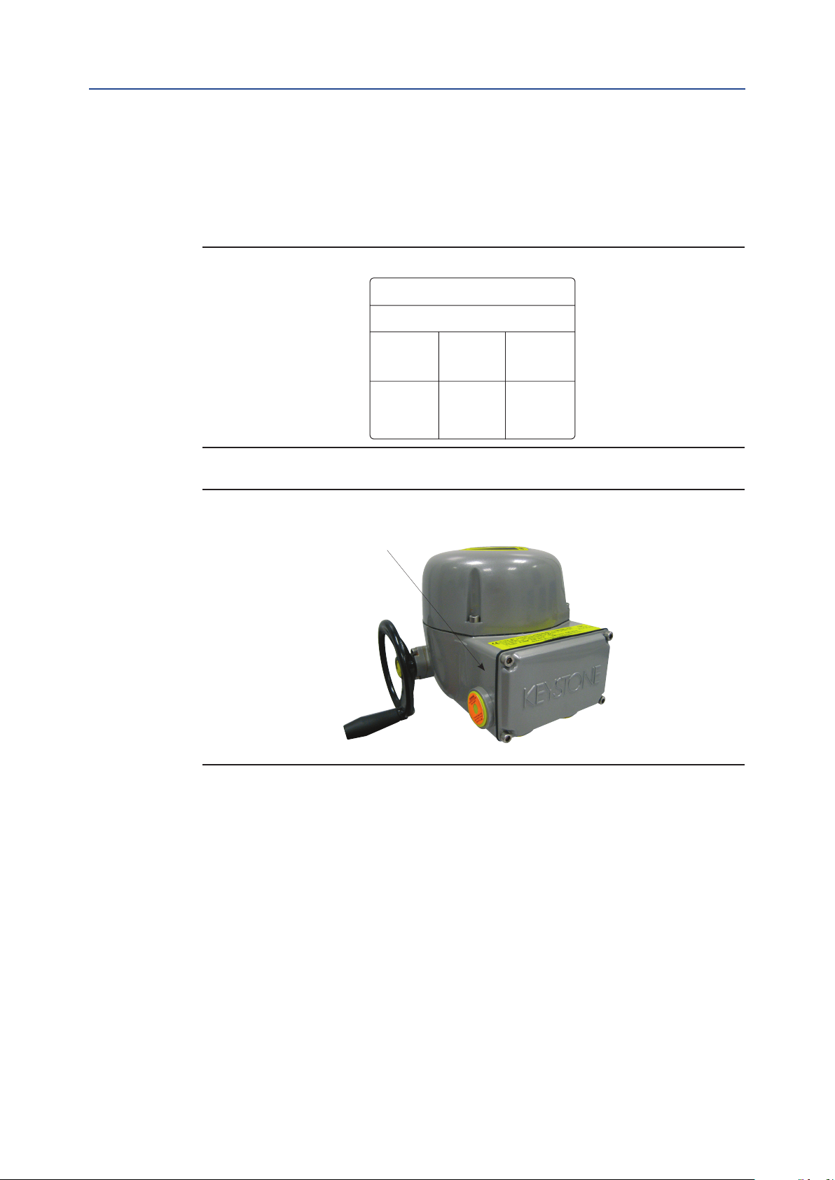
Figure 3
Local position indicator
Installation, Operation and Maintenance Manual
MAN-10-04-100-0711-EN Rev. 0
Control unit
Manual override
Mechanical gearing
Base ange
Cable entries
2.5 Description of the Main Parts
The Keystone EPI2 actuator consists of ve main parts:
• Base ange: for coupling the actuator to the valve
• Terminals enclosure: for power and signal cable connection through four
available cable entries
• Mehanical gearing: internal epicyclical gear reduction, which increases the torque
of the electric motor
• Control unit: integral control unit inclusive of electric motor with the relevant
driver, power and logic electronic card. By way of the mechanical gearing,
the electric motor operates the valve in normal working conditions
• Manual override: for actuator manual operation in case of power supply failure or
during actuator setting
Terminals enclosure
8
Machine Description

Installation, Operation and Maintenance Manual
MAN-10-04-100-0711-EN Rev. 0
2.6 Optional Modules
Keystone EPI2 actuators can be provided with several optional modules, as listed in the
table below. Please refer to this table for possible combinations of available modules.
Table 2. Optional Modules Selection Table
Section 2: Machine Description
October 2020
Order
code
P1
PA
P6
P7
P3
5P
6P
5D
6D
PG
OM1 I/O
additional module
OM3
local interface
Bluetooth
component
OM9
PDP V0/V1
OM11
DeviceNet
OM13
3 wires module
NOTE
1. Each optional module (OMx) will be provided with its own Installation and
Maintenance Instructions. All modules except OM13 are available for both
1-phase and 3-phase voltage versions.
2. Bluetooth component is integrated in the OM1, OM9 and OM11 card: not
available for integration by local organizations, as a stand alone unit.
3. OM13 is not available wit h 3-phase supply. Not available for LV version
1-phase voltage from 24 to 48 V DC/V AC.
Machine Description
9
Section 2: Machine Description
October 2020
2.7 Options Label
A label is always provided with base actuators where optional modules will have to be
checked out once they are installed after delivery at local organisations care.
Figure 4
Installation, Operation and Maintenance Manual
MAN-10-04-100-0711-EN Rev. 0
Options Label
S/N:
OM1OM3 OM9
OM11 OM13
Figure 5
Please make sure the label is stuck where shown
in the picture below.
10
Machine Description

Installation, Operation and Maintenance Manual
MAN-10-04-100-0711-EN Rev. 0
Section 3: Storage and Pre-Installation
Section 3: Storage and Pre-Installation
3.1 Checks to be Carried Out when the
Actuator is Received
NOTE
Not performing the following procedures will invalidate the product guarantee.
First of all check if the data on the nameplate (model, serial number, nominal torque,
nominal voltage range, protection degree, operating speed range, protection class, etc.)
correspond to the expected product data.
If the actuator is received already assembled onto the valve, the setting of the mechanical
stops and of the electric end-of- travel should have been already done during actuator
assembly onto the valve. An additional check is anyway recommended to verify that all
the requested settings have been completed as indicated in the present Instruction and
Operating Manual.
October 2020
If the actuator is received separately from the valve, the setting of the mechanical stops
and of the electric end-of-travel must be checked and, if necessary, carried out while
assembling the actuator onto the valve. In any case, all the setting operations described in
this Instruction and Operating Manual must be carried out. Check that the actuator was
not damaged during transport: in particular, inspect the local position indicator area glass.
If necessary, repair all damages to the paint-coat, etc. Check that the tted accessories
comply with those listed in the order acknowledgement and the delivery note.
3.2 Storage Procedure
3.2.1 General
The actuators leave the factory in perfect working conditions and with an excellent
nish, in order to maintain these characteristics until the actuator is installed on site, it is
necessary to observe a few rules and take appropriate measures during the storage period.
The basic version of Keystone EPI2 actuators is weather-proof to IP66/68. This condition
can only be maintained if the units are correctly installed and connected on site, and if
they were previously correctly stored. The standard plastic plugs used to close the cable
entries are not weather-proof, they just prevent the entry of undesired objects during
transport. Emerson can not accept responsibility for deterioration caused on site when
the covers are removed.
NOTE
The actuator handwheel is removed for transport. If the actuator must be shipped fully
assembled, please make sure the handwheel is packed securely to avoid all possible damage.
Storage and Pre-Installation
11

Section 3: Storage and Pre-Installation
October 2020
Installation, Operation and Maintenance Manual
MAN-10-04-100-0711-EN Rev. 0
3.2.2 Storage for a Brief Period (less than one year)
3.2.2.1 Indoor Storage
• Make sure the actuators are kept in a dry place, laid on a wooden pallet
(not directly on the oor surface) and protected from dust
• In very humid environments, a moisture absorbent desiccant packet should be
introduced in the motor enclosure. (Desiccant is not included in the actuator package)
3.2.2.2 Outdoor Storage
• Make sure the actuators are protected from the direct action of weather agents
(protection by a canvas tarp or similar).
Environment temperature: - 20 °C to +65 °C (-4 ° F to 149 °F)
• Place the actuators on a wooden pallet, or some raised plat form, so that they are
not in direct contact with the ground, and protected from dust
• In very humid environments, a moisture absorbent desiccant packet should be
introduced in the motor enclosure . (Desiccant is not included in the actuator package)
• If the actuators are supplied with standard plastic plugs, remove them from the
cable entries and replace them with weather-proof plugs
3.2.3 Long Period Storage (more than one year)
3.2.3.1 Indoor Storage
In addition to the instructions at point 3.2.2.1:
• If the actuators are supplied with standard plastic plugs, replace them with
weather-proof plugs
• The coupling parts (i.e. ange, etc.) must be coated with a protective oil or
grease; (if possible, blank off the ange by a protection disk)
3.2.3.2 Outdoor Storage
In addition to point 3.2.2.2:
• If the actuators are supplied with standard plastic plugs, replace them with
weather-proof (metal) plugs
• The coupling parts (i.e. ange, etc.) must be coated with a protective oil or
grease; (if possible, blank off the ange by a protection disk)
• Check the actuator general conditions, paying particular attention to the
terminal board
12
Storage and Pre-Installation

Installation, Operation and Maintenance Manual
MAN-10-04-100-0711-EN Rev. 0
Section 4: Installation
October 2020
Section 4: Installation
4.1 Checks to be Performed Before Installation
To assemble the actuator onto the valve proceed as follows:
• Check that the coupling dimensions of the valve ange and stem, or of the
relevant extension, meet the actuator coupling dimensions
• The electrical supply cables must be suitable for the power rating
• Gather the necessary tools for the assembly and conguration of the actuator controls
• Lubricate the valve stem with oil or grease to make the assembly easier: pay
attention not to contaminate with lubricant the ange surfaces which transmit
the actuator torque
• Clean the valve ange and remove anything that might prevent a perfect
adherence to the actuator ange and especially all traces of grease
• Install the actuator onto the valve so that the shaft output drive enters the
groove of the stem extension. This coupling must take place without forcing and
only with the weight of the actuator. When the actuator output shaft and the
valve stem are connected, check the holes of the valve ange. If they do not meet
with the holes of the spool piece ange or the stud bolts screwed into them, the
actuator shaft output drive must be rotated. Actuate the manual override until
coupling is made possible. Tighten the nuts of the connecting stud bolts evenly
• If possible, operate the actuator to verify it moves the valve smoothly
If a long storage period has occurred, before reinstalling the actuator, please:
• Check the status of the O-ring seals
• Check the installation of the plugs or cable glands on the cable entries
• Check whether the enclosure covers or the actuator body are cracked or broken
4.2 Working Condition
Standard Keystone EPI2 actuators are suitable for the following environment temperatures:
• -25 °C to +70 °C (-13 °F to +158 °F)
Special versions are available for extreme environment temperatures:
• -40 °C to +70 °C (-40 °F to +158 °F)
Installation
13

Section 4: Installation
October 2020
4.3 Coupling Block
The electric actuator is delivered with drive details and ange in accordance with the
technical characteristics required by the customer, ready to be installed onto the valve.
Only one insert is included in the actuator package delivered to end users.
NOTE
Check the ‘ambient temperature range’ printed on the nameplate, for the correct
utilisation with respect to the ambient temperature. Installation in ambient with
temperature range outside the specied values will invalidate the warranty.
WARNING
!
During normal operation the temperature of the actuator surface can reach 30 °C (86 °F)
above the ambient temperature.
Installation, Operation and Maintenance Manual
MAN-10-04-100-0711-EN Rev. 0
NOTE
In case the screws of the cover, of the terminal compartment and of the OM3 must be
replaced, SS Aisi 316 Class A4 grade 80 screw must be used with minimum yield strength
600 N/mm², The screw size is M6 X 25 mm. Other screws used for the assembly of the other
various parts of the explosionproof enclosure shall be a SS AISI 316 Class A4 Grade 70, with
minimum yield strength of 450 N/mm². Every time the main cover, the terminal compartment
cover and the OM3 are reassembled, make sure to tight all the screws with 5 Nm torque.
NOTE
For the model E171 and 2000 of the Keystone EPI2 Series only: during installation, the
user shall take into consideration that the actuator was assessed at a low risk impact
energy at 2J.
Figure 6 Overview of one type of insert and drive details of the Keystone EPI2
14
WARNING
!
Never lift the valve/actuator assembly without securing slings to both the valve and the
actuator. Never use the handwheel to lift the actuator.
Installation

Installation, Operation and Maintenance Manual
MAN-10-04-100-0711-EN Rev. 0
Section 4: Installation
4.4 Installation of the Keystone EPI2 Unit
onto a Valve
Move the valve to the completely open position. Manually bring the Keystone EPI2 to the
completely open position (verify the local mechanical indicator) and check the rotation
direction of actuator and valve. The actuator should be mounted for counter-clockwise
rotation to open and clockwise to close. The Keystone EPI2 unit can be installed onto the
valve in two different ways:
Direct mounting
Insert the valve shaft into the actuator bottom ange, taking care to correctly connect
the insert. Fix the screws on the valve ange to the actuator coupling block.
Bracket mounting
Install the bracket and the adapter onto the valve; then insert the valve shaft into the
actuator bottom ange, taking care to correctly connect the insert. Fix the screws
between the bracket and the valve ange and the actuator coupling block.
October 2020
4.5 Manual Operation
Keystone EPI2 electric actuators are supplied with a handwheel for manual override
as standard, to operate the actuator in case of power supply failure or during setting.
The handwheel is always engaged. For safe operation, the handwheel does not rotate
during electric operation. Turn the handwheel clockwise to close and counter-clockwise
to open. During manual operation, check the actuator maneuver on the local
mechanical indicator.
WARNING
!
Do not manually operate the actuator with devices other than the handwheel. Using
cheater bars, wheel wrenches, pipe wrenches, or other such devices on the actuator
handwheel may cause serious personal injury and/or damage to the actuator or valve.
Figure 7 Manual Operation
Installation
15

Section 4: Installation
October 2020
Installation, Operation and Maintenance Manual
MAN-10-04-100-0711-EN Rev. 0
4.6 Setting of the Angular Stroke: Mechanical Stops
It is important for the mechanical stops to end the angular stroke at both extreme
valve positions (fully open and fully closed). The setting of the angular stroke is
performed by adjusting the travel stop screw mounted on the actuator housing.
For the adjustment of the stop screw proceed as follows:
• Loosen the lock nut
• Screw 1: open
To set the mechanical stop in opening, manually bring the actuator to the
completely open position, then turn screw 1 clockwise to nd the correct
position, then block it by means of the nut
• Screw 2: close
To set the mechanical stop in closing, manually bring the actuator to the
completely close position, then tighten screw 2
If the actuator angular stroke is stopped before reaching the end position
(fully open or closed), proceed as follows:
• Unscrew the stop screw by turning it anticlockwise until the valve reaches
the correct position
• When unscrewing the stop screw, keep the lock nut still with a wrench so that
the sealing washer does not withdraw together with the screw
• Tighten the lock nut
If the actuator angular stroke is stopped beyond the end position (fully open or closed),
proceed as follows:
• Screw the stop screw by turning it clockwise until the valve reaches the correct position
• Tighten the lock nut
Figure 8 Setting of the Mechanical Stop
16
Installation
 Loading...