

KEYSTONE RMI DUBEX BUTTERFLY VALVES
InstallatIon and MaIntenance InstructIons
Please read these instructions carefully
Recommendations
1. Temperature: storage temperature
below25°C, above 0°C preferable
below15°C.
2. Humidity: storage conditions should be such
that condensation does not occur, store in
a dry environment. Maximal 50% relative
humidity.
3. Light: valve rubbers should be protected
from light, in particular direct sunlight or
strong artificial light with high ultra violet.
4. Ozone: storage rooms should not
contain any equipment generating ozone.
E.g.lamps, electric motors.
IMPORTANT
Before valves are being installed or used the
following actions are recommended.
1. Valves/parts have to be inspected and
thoroughly cleaned if required.
2. Rubber parts need to be greased with silicone
grease if not present anymore.
3. All surfaces in contact with seats have to be
INTENDED VALVE USE
The valve is intended to be used only in
applications within the pressure/temperature
limits indicated in the P/T diagram of the
product manual.
1 STORAGE AND HANDLING
1.1 Storage
When valves are to be stored for some time
(2months or more) before being fitted, storage
should be in the original delivery crates or
cases.
1.1.1 Storage conditions
The valves should be stored off the ground in a
clean, dry indoor area.
Protect the valve from temperature and
humidity extremes, and exposure to excessive
dust, moisture, vibration, deformations,
sunlight and ozone.
thoroughly cleaned and greased with silicone
grease if stored for more than 5 months.
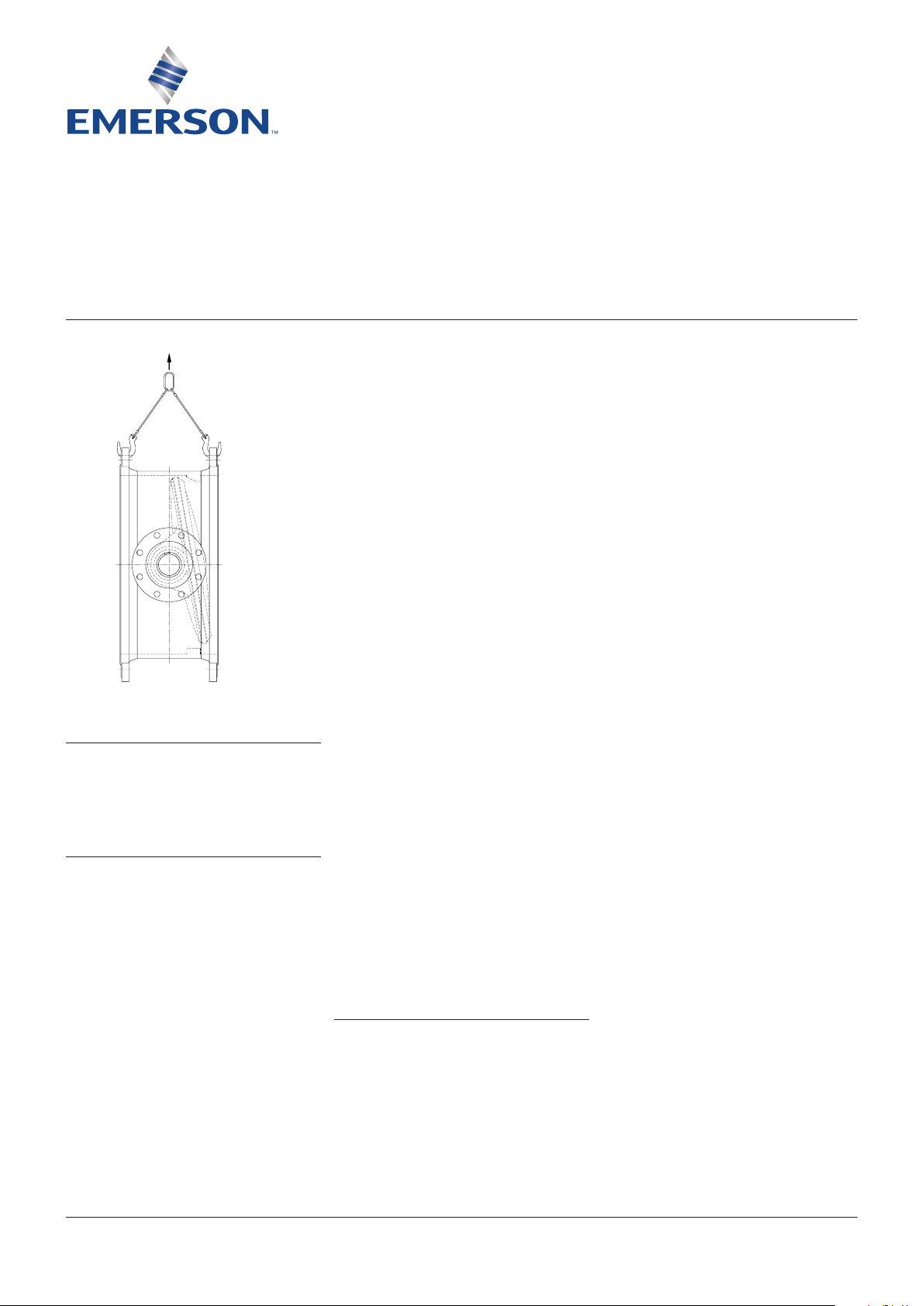
1.2 Handling
To prevent damage during lifting, the valves
should be lifted by hand or with appropriate
lifting equipment. The valves should be
protected from external events e.g. (bumps,
hitting and vibration) during transport.
Any flange protection caps need to be removed
before the valve is mounted in the pipeline.
Lift the valve with great care from the transport
package (crate, pallet). While handling or
installing the valve, ensure that no damage
occurs to the valve, the pneumatic/electrical/
hydraulic actuator or other instrumentation.
2 SPARE PARTS
Only original RMI spare parts are allowed to be
used. Safe operation can not be guaranteed if
third party spare parts are used.
www.valves.emerson.com © 2017 Emerson. All rights reserved.
VCIOM-02129-EN 14/07
KEYSTONE RMI DUBEX BUTTERFLY VALVES
InstallatIon and MaIntenance InstructIons
3 INSTALLATION
WARNING
For safety reasons, it is important to take the
following precautions before starting to work on
the valve:
1. Personnel making any adjustments to the
valves should utilize suitable equipment. All
required personal protection means should be
worn.
2. The line must be depressurized before
installing the valve.
3. Installation and handling of valves should be
done only by personnel that is trained in all
aspects of manual and mechanical handling
techniques.
4. Misuse of the valve is not allowed.
Forexample: the valve, handles, actuators
or other parts may not be used as
‘climbingtools’.
5. Ensure that valve pressure/temperature
limitations marked on the valve’s tagplate
are within the service conditions. The trim
number on the valve’s tagplate identifies
the valve materials. See Product Manual for
valve specific P/T diagram and trim number
definition.
6. Ensure that valve materials are compatible
with the pipeline fluid.
3.1 Visual valve inspection
1. Confirm that the materials of construction
listed on the valve tagplate are appropriate
for the service intended and are as
specified.
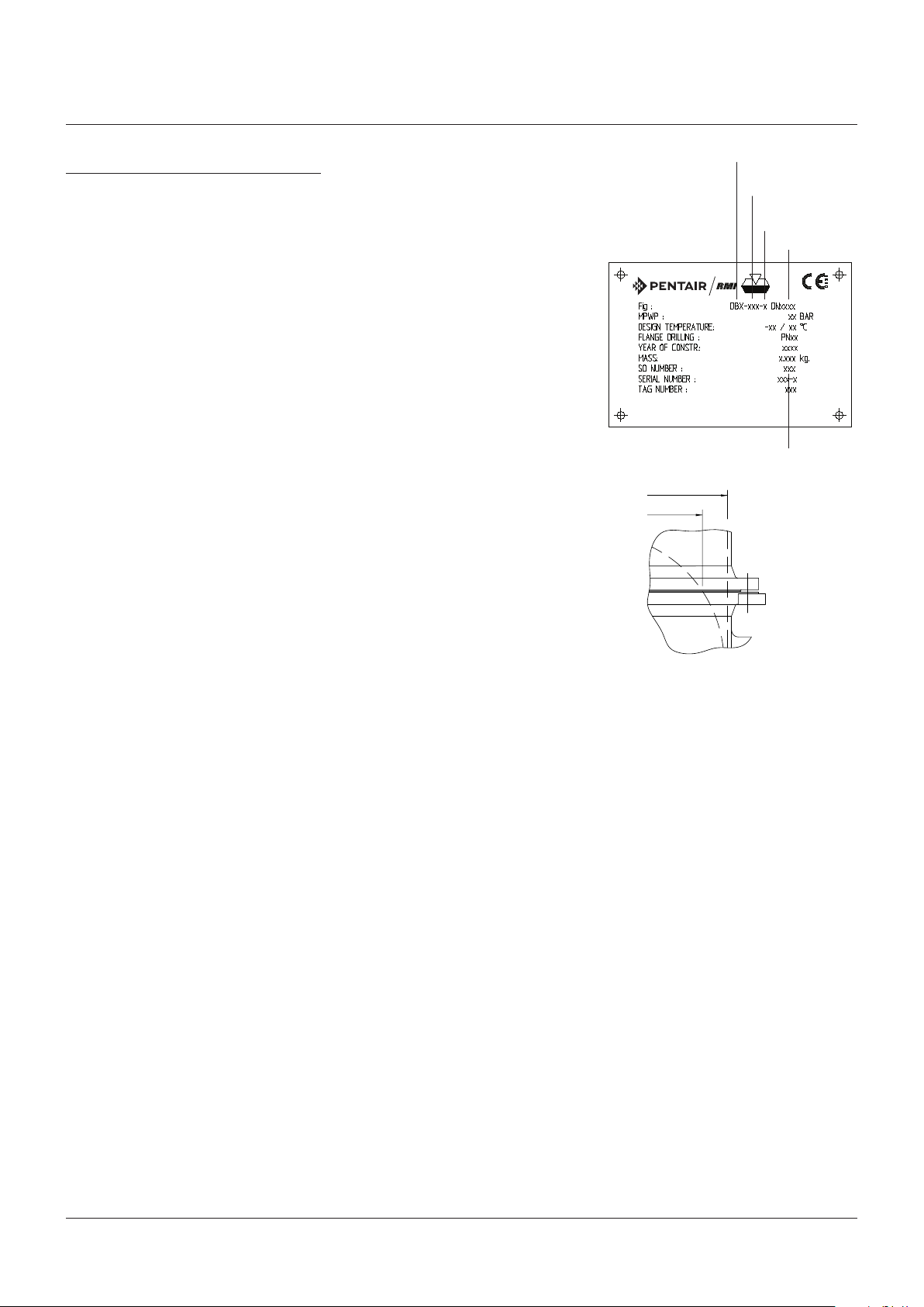
2. Tag/name plate identification
Manufacturer: Emerson RMI
Figure: Dubex
Material trim: e.g. 804
Direction: U(nidirectional) or
B(idirectional)
Size: e.g. DN 1000
Tag no.: if required
Design pressure: e.g. PN 16
Design temperature: e.g. 20°C
Year of construction: e.g. 2004
Mass: e.g. 2500 kg
3.2 Flange and pipe compatibility
Check matching of flange drilling pattern of
valve and pipe before assembly.
Flanges have to meet the following
requirements:
- The face inside diameter should be:
D min.: The valve Q-dimension + adequate disc
clearance.
D max.: The inside diameter (ID) of standard
pipe for the nominal size ISO 4200.
Use flange bolting in agreement with
appropriate standard.
3.3 Valve installation
The valves are delivered as uni- or bidirectional.
An uni-directional valve is equipped with an
arrow on the body. The arrow points from
the high pressure side to the low pressure
side. The preferred direction in the pipeline is
positioning the valve with the seat downstream
of the shaft valve. The valve will control flow
not exactly equal in both directions. The
recommended installation position is shaft
horizontal and the lower disc edge opening
downstream (especially for slurry service and
media with a tendency for sedimentation).
For optimum valve control and smooth
performance, it is recommended to have 10 to
20 pipe diameters of straight run inlet piping
and 3 to 5 pipe diameters straight outlet piping.
Do not use the valve to spread the flanges.
D max/min
Q
Figure
Material
identification
Unidirectional or
Bidirectional
Size
Sales order nr.
2
 Loading...