

Page 1
KEYSTONE WINN SURE-SEAL RUBBER LINED BUTTERFLY VALVES
OperatiOn, installatiOn and Maintenance instructiOns
Before installation these instructions must be fully read and understood
2 INSTALLATION
2.1 Wafer design
This valve is of the wafer design intended for
‘sandwiching’ between two pipe flanges by
means of through bolting and is supplied with
locating holes or lugs to ensure that the valve
blade is positioned centrally in the pipeline
anddoes not foul the pipe when opened.
It should be noted that the valve can be
positioned either with the valve spindle
GENERAL
sittingvertically or horizontally.
The Winn Sure-Seal is a new generation of
high quality butterfly valves which incorporate
a bonded resilient liner and give additional
benefits of easy replacement and a wide
choiceof materials.
1 STORAGE
1.1 Storage conditions
Environmental conditions may be particular
harmful to vulcanized rubbers, therefore
the careful choice of storage conditions
isimportant.
1.2 Temperature
The storage temperature should be between
10°C and 25°C.
1.3 Humidity
Moist conditions should be avoided; storage
conditions should be such that condensation
does not occur.
1.4 Light
The valve shall be protected from light, in
particular direct sunlight and strong artificial
light with a high ultra-violet content.
1.5 Ozone
Since ozone is particularly harmful to
vulcanized rubber, storage rooms should
not contain any equipment that is capable
of generating ozone, such as mercury vapor
lamps, high voltage equipment, electric motors
or other equipment which may give rise to
electric sparks or silent electrical discharges.
As the valve liner extends over the flange
faces this forms a ‘built in’ gasket between the
mating flanges, therefore no flange joints are
required when using these valves. To ensure
a perfect flange seal, the mating flange faces
should be bolted up until there is a metal
contact between the flange faces and the valve
body. Care should be taken to ensure that no
sharp edges or burrs are left on the flange
faceas this may damage the liner.
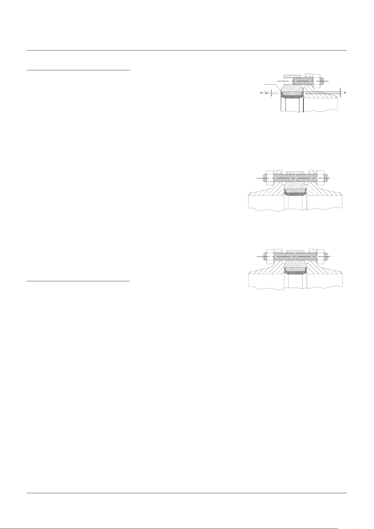
2.2 Lug design
The foregoing applies when the valve is fitted
in a ‘line end’ situation, spigots on both the
body bore and seat outside diameter restrict
axial movement of the seat. The valve must be
fitted with spigots to the open end, see Fig. 1.
The spigotted end can be easily be identified
by measuring the radial width of the outer
rubber seal, the spigotted end seal being
(1.5mm)narrower.
2.3 Manual operators
Valves fitted with manual operators have
handlevers or handwheels sized to ensure
ease of operation, and under no circumstances
should wheel spanners or additional leverage
be applied to open or close the valve. All geared
operators are fitted with built in stops and these
are set in our works before dispatch.
These settings should not be altered.
Where valves are supplied without handwheels,
reference should be made to appropriate
contract drawing for recommended operator
input torques.
1
/
16”
www.valves.emerson.com © 2017 Emerson. All rights reserved.
VCIOM-02487-EN 15/02
Page 2
KEYSTONE WINN SURE-SEAL RUBBER LINED BUTTERFLY VALVES
OperatiOn, installatiOn and Maintenance instructiOns
3 MAINTENANCE
No maintenance is required other that periodic
inspection to ensure satisfactory operation and
satisfactory sealing of the valve spindle.
If the valve is fitted with an enclosed geared
operator, it is recommended that at least
once every year, if possible, the gearbox
cover can beremoved and grease added
if necessary (forappropriate grease see
gearboxnameplate).
4 DISMANTLING
The valve should be suitably supported
and then removed from the pipeline after
withdrawal of the flange bolts. Remove the
operator by releasing the necessary bolts and
lift directly off the valve any mounting plates
orbrackets, if fitted, being removed next.
WARNING
Before attempting any maintenance, ensure
that the system has been depressurized and if
necessary, drained of all dangerous chemicals.
4.1 Wafer design
To dismantle the valve, the plastic plug (12) in
the tail end should be removed making the tie
bar visible. The nut (8) should be removed and
discarded.
With the valve in the part open position the
upper shaft (5) should be removed either
by pulling the shaft from the drive end, or
by pushing the bar (7) from the tail end, of
thevalve.
The lower shaft (6) can now be removed using
a piece of bar pushed through the disc from
thedrive end.
Having removed the lower-shaft, this disc (4)
can be removed from the seat using a soft
hammer.
The liner (2) can now be removed from the
body (1) by simply slicing or knocking it
axiallythrough the body bore.
The wiper seal (10) can be prized from its
location using a sharp instrument or wire.
4.2 Lug design
The foregoing applies with the exception the
liner can only be removed from the body in
onedirection - see Fig. 1.
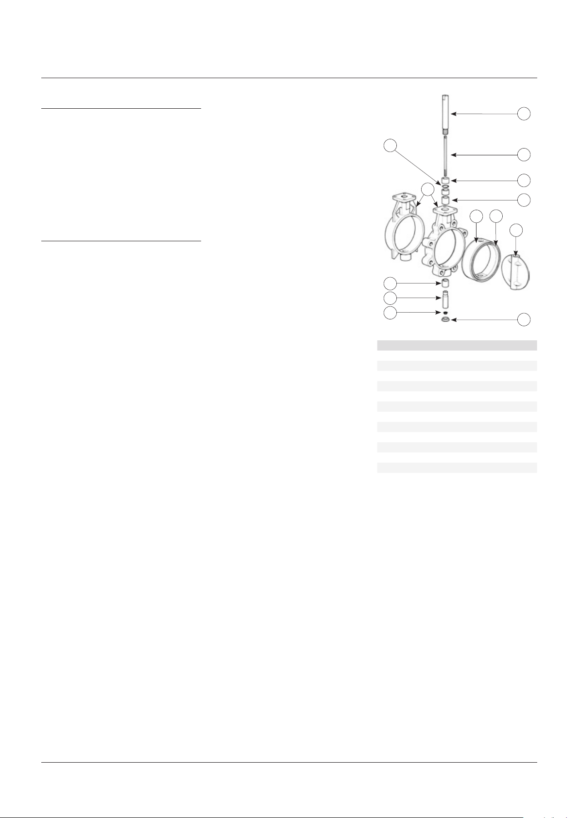
10
1
9
6
8
Item Component
1 Body
2 Liner
3 Backing ring
4 Disc
5 Shaft (upper)
6 Shaft (lower)
7 Shaft tie bar
8 Tie bar nut
9 Shaft bearing
10 Wiper ring
11 Ring retainer
12 Body plug
5
7
11
9
3
2
4
12
NOTE
DN 350 and above have single piece shaft and
pindesign.
2
Page 3
KEYSTONE WINN SURE-SEAL RUBBER LINED BUTTERFLY VALVES
OperatiOn, installatiOn and Maintenance instructiOns
5 ASSEMBLY
5.1 Wafer design
The liner (2) should fitted into the body (1),
andthe shaft bores aligned.
As the dimensions across the disc ‘flats’ results
in an interference fit in the region of the spindle
bore, the disc (4) should be carefully pressed
into the seat until the drive end of thebody.
Apply silicone grease around the seating
surface of the liner to aid assembly. Ensure the
tie bar (7) is secured by the upper shaft (5).
A missing spline on the upper shaft and disc
ensure the keyway is assembled parallel to the
disc. Care should be taken to ensure correct
fitting of these components. Once the spline
has started to enter, the stem may be hit hard
down into the disc using a soft hammer.
The lower shaft (6) can now be fitted and
alsohit hard down into the disc.
Using a retaining compound a new nut (8)
should be fitted to the tie bar and tightened
using a socket or box key.
Finally a new plastic body plug (12) should
bereplaced in the tail end.
The operator can now be fitted.
5.2 Lug design
The foregoing applies with the exception that
the liner can only be fitted into the body in one
direction - see Fig. 1.
FIGURE 1
Spigotted end
Open end
Lugged with tapped holes - open ended
Note: spiggoted end must be at the open
endside
FIGURE 2
Lugged with tapped holes - flanged both ends
FIGURE 3
6 RECOMMENDED SPARES
1 - Seat
1 - Wiper seal
1 - Locking nut
1 - Plastic cap
Wafer/lugged with plain holes - flanged
bothends
3
Page 4

© 2017 Emerson. All rights reserved.
4
 Loading...