

KEYSTONE
Butterfly valve Figure 40 K-set
Installation & Maintenance Instructions
Please read these instructions carefully
This symbol indicates important
messages and safety instructions.
Hazard potentials:
• disregarding of instructions
• improper use of product
• insufficiently qualified personnel
Valve application to be within the pressure/
temperature limits indicated in the P/T
diagram.
Essential points and functions of the valve
should be inspected on a regular basis.
When the valve is used in an end-of-line
function, PED Cat-I applications are allowed
only. For other categories, contact factory.
1 Storage & handling
1.1 Protection
Keystone valves are delivered with protection in accordance with the Keystone Engineering
Instructions, to protect the valve seats and disc from damage. Wrapping and/or covers should
be left in place until immediately before fitting to the pipe.
The commissioning set is supplied completely assembled, except for the metering plugs.
1.2 Storage
When valves are to be stored for some time (2 months or more) before being fitted, storage
should be in the original delivery crates or cases.
1.2.1 Storage conditions
The valves should be stored off the ground in a clean, dry indoor area.
Protect the valve from temperature and humidity extremes, and exposure to excessive dust,
moisture, vibration, deformations, sunlight and ozone.
Recommendations
1. Temperature: storage temperature below 25°C, above 0°C preferable below 15°C.
2. Humidity: storage conditions should be such that condensation does not occur, store in a
dry environment. Maximal 50% relative humidity.
3. Light: valve rubbers should be protected from light, in particular direct sunlight or strong
artificial light with high ultra violet.
4. Ozone: storage rooms should not contain any equipment generating ozone. E.g. lamps,
electric motors.
Important
Before valves are being installed or used the following actions are recommended.
1. Valves/parts have to be inspected and thoroughly cleaned if required.
2. Rubber parts need to be greased with silicone grease if not present anymore.
3. All surfaces in contact with seats have to be thoroughly cleaned and greased with silicone
grease if stored for more than 5 months.
www.valves.emerson.com
1.3 Handling
1.3.1 Packed valves
Lifting and handling of the packed valves in crates should be carried out by appropriate lifting
equipment. If a fork lift truck is used, appropriate fork hitches are required.
The lifting and handling of packed valves in cases will be carried out in the lifting points.
The transportation of all packed material should be carried out safely and according the local
safety regulations.
1.3.2 Unpacked valves
The lifting and the handling of these valves have to be carried out by using appropriate means
and by respecting the carrying limits. The handling must, preferably, be carried out on pallets,
protecting the machined surfaces and seat to avoid damage.
When lifting the large dimension valves, the sling and the hooking of the load must be carried
out by using the appropriate tools (brackets, hook, fasteners) and load balancing tools in order
to prevent the valves from falling or moving during the lifting and handling.
The valve may be lifted only by slings attached to the flange holes or valve body; never to the
actuator or the valve opening.
Emerson reserves the right to change the contents without notice EBPJD-0127-EN-1305
Butterfly valve Figure 40 K-set
Installation & Maintenance Instructions
2 Installation
WARNING!
For safety reasons, it is important to take the following precautions before you start work on the valve:
1. Personnel making any adjustments to the valves should utilize suitable equipment. All
required personal protection means should be worn.
2. The line must be depressurized before installing the valve.
3. Personnel trained in all aspects of manual and mechanical handling techniques must carry
out handling of the valves.
4. Misuse of the valve is not allowed. For example: the valve, handles, actuators or other parts
may not be used as ‘climbing tools’.
5. Ensure that valve pressure/temperature limitations marked on the identification tag are within
the service conditions. The trim number on the valve’s tagplate identifies the valve materials.
See Product Manual for valve specific P/T diagram and trim number definition.
6. Ensure that valve materials are compatible with the pipeline fluid.
2.1 Valve inspection
1. Carefully remove the valve from the shipping package (box or pallet) avoiding any damage
to the valve or, in case of automated valves, to the electric or pneumatic/hydraulic actuator
or instrumentation.
2. Confirm that the materials of construction listed on the valve nameplate are appropriate for
the service intended and are as specified.
3. It is not allowed to use third party spare parts. In case of third party spare parts, safe
operation is not guaranteed.
YY
Q
D max/min
2.2 Flange and pipe compatibility
Check matching of flange drilling pattern of valve and pipe before assembly.
Flanges have to meet the following requirements:
- The face inside diameter should be:
D min. : The valve Q-dimension + adequate disc clearance.
D max. : The optimum inside diameter (ID) is equal to the inside diameter of flange standard
EN 1092-1, table 8, type 11. For larger than D max inside diameters or other flange
types please contact your local Emerson Sales organization, as larger inside diameters
might result in reduced valve functionality.
- If the flange (or pipe) is provided with a raised face, the diameter of this shall be at least 8
mm larger than the YY-dimension of the valve.
The use of the flange-gaskets is not allowed since it might damage the valve.
The Keystone seat-face design eliminates the need for the gaskets.
Use flange bolting in agreement with appropriate standard.
Do not use flange gaskets, these lead to valve damage!
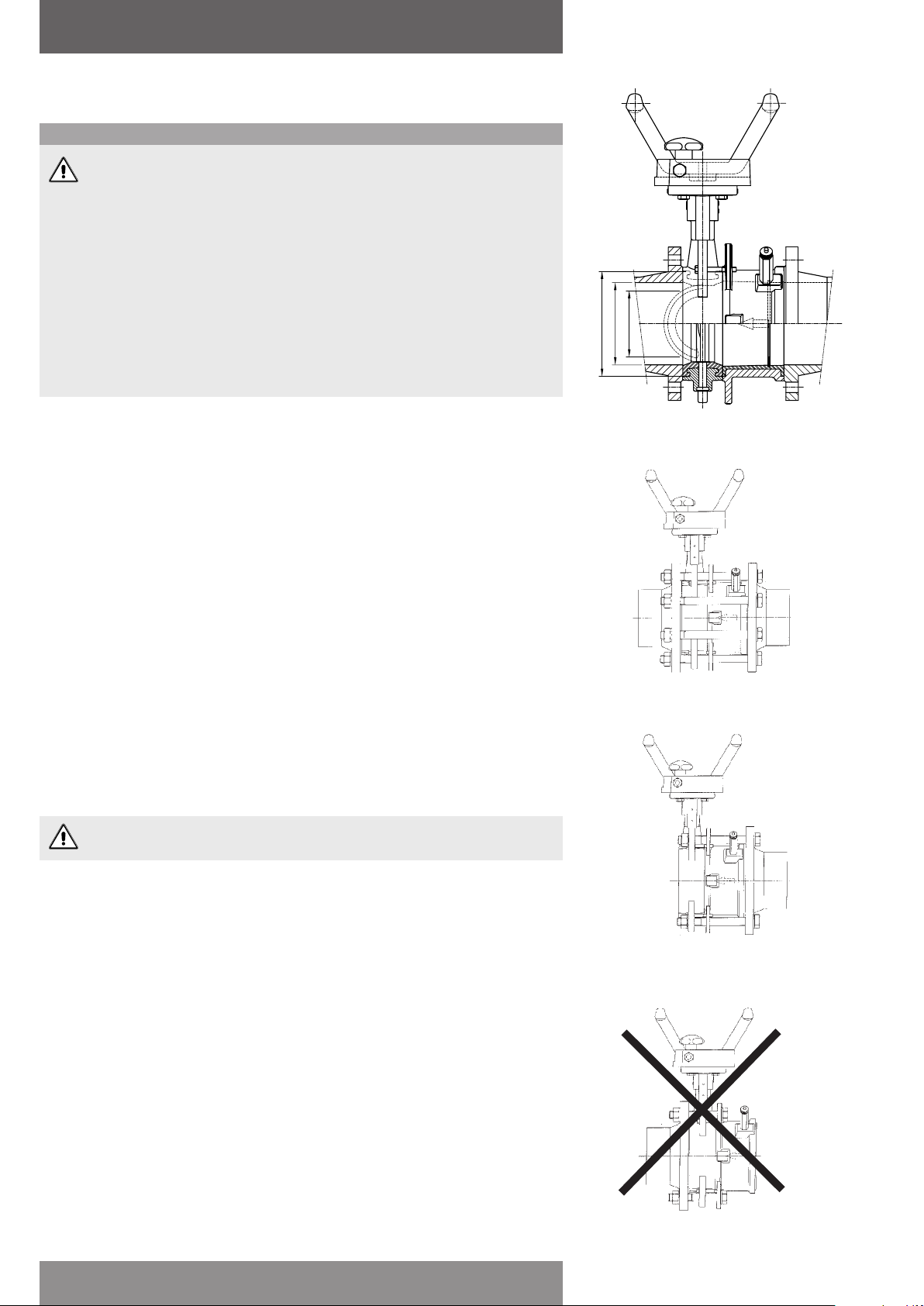
2.3 Valve installation
The valve is suitable for measuring flow in one direction only; the attached butterfly valve is
pressure tight in both flow directions. See picture 1 for correct valve positioning.
The measuring error of a commissioning valve largely depends on proper design of mating
piping and installation of the unit. Please note the following points:
• A length of 5 times the pipe diameter upstream the orifice body and 2,5 times the pipe
diameter downstream must be straight without fittings, reducers or any other obstruction.
• The inside diameters of the flanges must correspond with the inside diameter of the orifice
body.
• The commissioning set must be properly aligned to the mating flanges and piping.
The commissioning set may be used as end of line valve with a maximum static pressure of
6 bar only, if the flange on the valve side is removed (see picture 2). Installations as end of line
valves shown in picture 3 is not allowed; it can cause serious damage to the orifice lugs.
1. Normal installation
2. Allowed installation for end of line service.
Max. 6 bar static pressure
Emerson reserves the right to change the contents without notice page 2
3. Not allowed for end of line service
 Loading...