

Page 1

Installation, Operation and Maintenance Manual
Keystone OM1 - EPI2
Modulating Input/Output Module
VCIOM-01494-EN Rev. 0
June 2022
Page 2

Notes
June 2022
Installation, Operation and Maintenance Manual
VCIOM-01494-EN Rev. 0
This page intentionally left blank
Page 3

Installation, Operation and Maintenance Manual
VCIOM-01494-EN Rev. 0
Table of Contents
Section 1: Optional Module 1: Modulating I/O Module
1.1 OM1 Module Functionality ......................................................................... 1
1.2 Manufacturer ............................................................................................. 2
Section 2: Installation
2.1 Assembling Procedure for Models 63-125 Nm
Old Version (US or Non-US Market) ............................................................. 4
2.2 Assembling Procedure for Models 250-500-1000-2000 Nm
Old Version (US or Non-US Market) ............................................................. 7
2.3 Assembling Procedure for Models 63-125 Nm
New Version (US or Non-US Market) ............................................................ 9
2.4 Assembling Procedure for Models 250-500-1000-2000 Nm
New Version (US or Non-US Market) ........................................................... 12
Table of Contents
June 2022
Section 3: OM1 Module Setting and Conguration
3.1 Local Setting of OM1 ................................................................................... 15
3.1.1 OM1 Module Default General Setting ............................................... 15
3.1.2 OM1 Module Setting ........................................................................ 15
3.1.3 4 - 20 mA/0 - 10 V DC Input Setting ................................................. 18
3.1.4 4 - 20 mA/0 - 10 V DC Output setting .............................................. 18
3.1.5 Relays AUXC1, AUXC2, AUXC3 and AUXC4 Settings ......................... 19
3.1.6 Dead Band Settings .......................................................................... 21
3.1.7 Position Request .............................................................................. 21
3.2 Additional Bluetooth Optional Card ............................................................ 21
Section 4: Monitor Relay Functionality and Setting
Monitor Relay Functionality and Setting ............................................................... 22
Section 5: OM1 Kits
OM1 Kits .............................................................................................................. 23
Section 6: OM1 Wiring Diagram
OM1 Wiring Diagram ........................................................................................... 27
Table of Contents
i
Page 4

Notes
June 2022
Installation, Operation and Maintenance Manual
VCIOM-01494-EN Rev. 0
This page intentionally left blank
Page 5

Installation, Operation and Maintenance Manual
VCIOM-01494-EN Rev. 0
NOTE:
Before installation, these instructions must be fully read and understood.
Section 1: Optional Module 1: Modulating I/O Module
Section 1: Optional Module 1:
Modulating I/O Module
1.1 OM1 Module Functionality
The OM1 Modulating I/O module is supplied as an option on Keystone EPI2 actuators.
It is possible to receive the actuator already equipped with the OM1, ordering it with
the basic feature.
Alternatively, it is possible to order the OM1 as a separate kit and install it in the basic
actuator in the factory or in the field.
The OM1 is an optional module suitable to accomplish the following EPI2 actuator
additional functionalities:
June 2022
• Positioner with analog position input 4 - 20 mA or 0 - 10 V DC optocoupled
• Analog output position transmitter 4 - 20 mA or 0 - 10 V DC optocoupled
• Monitor relay remote indication for:
— loss of power
— stop by torque out of limit
— direction failure
— over-temperature
— position sensor alarm
— valve jammed
— hardware malfunction
— alarm on local control panel (if present)
— stroke failure
• Blinker/Local selector relay remote indication
• 4 additional SPST output contacts to be set independently at 12.5% intervals along
the stroke. Contacts are congurable (make or break)
• Optional Bluetooth connection feature
NOTE:
For decommissioning instructions, please refer to the relevant section in the EPI2 manual
ref. VCIOM-15516-EN.
Optional Module 1: Modulating I/O Module
1
Page 6

Section 1: Optional Module 1: Modulating I/O Module
June 2022
WARNING
!
EPI2 actuator must be electrically isolated before any disassembling or reassembling
operations. Before any disassembling or reassembling operations, please follow in
detail the relevant paragraph of the basic installation and operating manual (latest
revision available).
WARNING
!
The electronic parts of the EPI2 actuators and all option modules can be damaged by
a discharge of static electricity. Before you start, touch a grounded metal surface to
discharge any static electricity.
WARNING
!
It is assumed that the installation, conguration, commissioning, maintenance, and repair
works are carried out by qualied personnel and checked by responsible specialists.
Installation, Operation and Maintenance Manual
VCIOM-01494-EN Rev. 0
WARNING
!
Repair work, other than operations outlined in this manual, is strictly reserved to qualied
Keystone personnel or to personnel authorized by the company itself.
1.2 Manufacturer
Manufacturer with respect to Machinery Directive 98/37: as specied on the motor label.
2
Optional Module 1: Modulating I/O Module
Page 7

Installation, Operation and Maintenance Manual
VCIOM-01494-EN Rev. 0
Section 2: Installation
To assemble the OM1 into the EPI2 actuator, proceed as follows:
• Ensure that all the parts received with the OM1 are available as described in
Section 5.
• Using Section 5, select only mechanical parts (screws and spacers) depending on
actuator models.
• Gather the right tools for the assembly and for setting the actuator controls.
• With an Allen wrench of 5 mm, unscrew the cover screws as shown in Figure 1.
• Remove the actuator cover as shown in Figure 2.
Figure 1
Section 2: Installation
June 2022
Figure 2
Follow one of the following assembling procedures depending on actuator model.
Installation
3
Page 8

Section 2: Installation
June 2022
Installation, Operation and Maintenance Manual
VCIOM-01494-EN Rev. 0
2.1 Assembling Procedure for Models 63-125 Nm
Old Version (US or Non US Market)
• Detect the 4 black cables required for the OM1 which are already included in the
basic actuator as shown in Figure 3.
• Connect the at cable furnished into the kit to connector J9 on OM1 as shown in
Figure 4.
Figure 3
Figure 4
• Unscrew the 3 screws as shown in Figure 5:
— 3 pcs M3x10
• Tighten the 3 metal spacers as shown in Figure 6.
4
Installation
Page 9

Installation, Operation and Maintenance Manual
VCIOM-01494-EN Rev. 0
Figure 5
Figure 6
Section 2: Installation
June 2022
screw
metal spacer
• In Figure 7, connect OM1 at cable to connector J8 on the logic board.
• In Figure 8, place the OM1 card onto the spacer and tighten the 4 screws.
Figure 7
Installation
5
Page 10

Section 2: Installation
June 2022
Figure 8
• Connect the following connector as shown in Figure 9:
Installation, Operation and Maintenance Manual
VCIOM-01494-EN Rev. 0
screw
— the 8-pin connector to connector J3 on OM1
— the 4-pin connector to connector J2 on OM1
— the 3-pin connector to connector J6 on OM1
— the 2-pin connector to connector J7 on OM1
Figure 9
6
Installation
Page 11

Installation, Operation and Maintenance Manual
VCIOM-01494-EN Rev. 0
2.2 Assembling Procedure for Models
250-500-1000-2000 Nm Old Version
(US or Non-US Market)
• Detect the 4 black cables required for the OM1 which are already included in the
basic actuator; disassemble local mechanical indicator as shown in Figure 10.
Figure 10
Section 2: Installation
June 2022
• In Figure 11, connect the at cable furnished into the kit to connector J9 on OM1.
• In Figure 12, connect the OM1 at cable to the connector on the logic board.
Figure 11
Installation
7
Page 12

Section 2: Installation
June 2022
Figure 12
• Place the OM1 card onto the heatsink spacers and tighten the 4 screws; assemble
• Connect the following connector as shown in Figure 14:
Installation, Operation and Maintenance Manual
VCIOM-01494-EN Rev. 0
local mechanical indicator shown in Figure 13.
— the 8-pin connector to connector J3 on OM1
— the 4-pin connector to connector J2 on OM1
— the 3-pin connector to connector J6 on OM1
— the 2-pin connector to connector J7 on OM1
Figure 13
Figure 14
screw
8
Installation
Page 13

Installation, Operation and Maintenance Manual
VCIOM-01494-EN Rev. 0
Section 2: Installation
June 2022
2.3 Assembling Procedure for Models 63-125 Nm
New Version (US or Non-US Market)
• Detect the 3 black cables required for the OM1 which are already included in the
basic actuator as shown in Figure 15.
• Connect the at cable furnished into the kit to connector J9 on OM1 as shown in
Figure 16.
Figure 15
Figure 16
Installation
9
Page 14

Section 2: Installation
June 2022
• Unscrew the 3 screws as shown in Figure 17.
• Tighten the 3 metal spacers and the plastic metal spacer as shown in Figure 18.
Figure 17
Installation, Operation and Maintenance Manual
VCIOM-01494-EN Rev. 0
screw
Figure 18
metal spacer
plastic spacer
• Connect OM1 at cable to connector J8 on the logic board as shown in Figure 19.
• Place the OM1 card onto the spares and tighten the 3 screws as shown in Figure 20.
10
Installation
Page 15

Installation, Operation and Maintenance Manual
VCIOM-01494-EN Rev. 0
Figure 19
Figure 20
Section 2: Installation
June 2022
screw
M3x8
• Connect the following connectors as shown in Figure 21:
— the 8-pin connector to connector J3 on OM1
— the 3-pin connector to connector J6 on OM1
— the 2-pin connector to connector J7 on OM1
Figure 21
Installation
11
Page 16

Section 2: Installation
June 2022
Installation, Operation and Maintenance Manual
2.4 Assembling Procedure for Models
250-500-1000-2000 Nm New Version
(US or Non-US Market)
• Detect the 3 black cables required for the OM1 which are already included in the
basic actuator as shown in Figure 22.
• Connect the at cable furnished into the kit to connector J9 on OM1 as shown in
Figure 23.
Figure 22
black cables
VCIOM-01494-EN Rev. 0
Figure 23
• Add N
• Disassemble local mechanical indicator and connect OM1 at cable to connector
°
3 spacers and unscrew the screw (A) that x the motor cable as shown in
Figure 24.
on the logic board as shown in Figure 25.
12
Installation
Page 17

Installation, Operation and Maintenance Manual
VCIOM-01494-EN Rev. 0
Figure 24
Section 2: Installation
June 2022
Figure 25
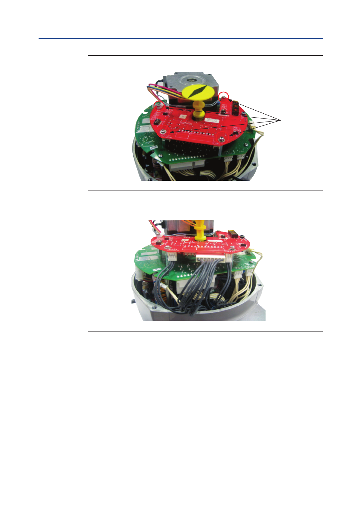
• Place the OM1 card onto the spacers and tighten the 4 screws; assemble local
mechanical indicator as shown in Figure 26.
• Connect the following connectors as shown in Figure 27:
— the 8-pin connector to connector J3 on OM1
— the 3-pin connector to connector J6 on OM1
— the 2-pin connector to connector J7 on OM1
Installation
13
Page 18
Section 2: Installation
June 2022
Figure 26
Installation, Operation and Maintenance Manual
VCIOM-01494-EN Rev. 0
screws
Figure 27
NOTE:
Please note that all the connectors provided with the base actuator and all optional cards
are different from each other (in terms of design and number of pins). In no way is it
possible to make a wrong connection.
14
• The OM1 card is now connected.
• Replace the actuator cover and x it properly.
Installation
Page 19

Installation, Operation and Maintenance Manual
VCIOM-01494-EN Rev. 0
Section 3: OM1 Module Setting and Conguration
Section 3: OM1 Module Setting
and Configuration
For the EPI2 basic actuator settings, please refer to the Installation, Operation and
Maintenance Manual.
The OM1 can be set once the basic EPI2 has been completely set.
The OM1 configuration can be carried out through the control panel on the optional
card itself. In order to get access to the panel, remove the actuator cover and when
the setting is complete replace the cover properly.
3.1 Local Setting of the OM1
3.1.1 OM1 Module Default General Setting
June 2022
Please refer to the last column of Table 1.
3.1.2 OM1 Module Setting
If the application requires a different actuator setting than by default, please proceed as
described in this section.
The setting of the actuator parameters is made through the following tools:
— Three selector switches SW7, SW8, and SW9 for functionalities settings
— Input and output voltage/current selection (through switches SW1, SW3,
SW5, and SW6)
— Monitor relay contact type (through the welding pin J1)
— ENTER pushbutton SW2 (conrmation pushbutton)
— Dip switch SW4 (enable conguration mode)
— Red LED for EN TER action conrmation (switches on when setting
is conrmed)
1. Set the requested parameter and functionality accordingly to the following table.
2. Enter setup conguration: move SW4 switch to position ON (conguration mode).
3. Conrm each setting by pushing ENTER pushbutton SW2.
4. When pushing SW2, the red LED switches ON for conrmation.
5. Exit conguration mode (move SW4 switch to position 1).
6. Repeat this setting for each parameter.
WARNING
!
Do not electrically operate the EPI2 when the electrical enclosures are removed. Operating
the unit with the electrical enclosures removed could cause personal injury.
OM1 Module Setting and Conguration
15
Page 20

Section 3: OM1 Module Setting and Conguration
June 2022
Figure 28
Installation, Operation and Maintenance Manual
VCIOM-01494-EN Rev. 0
SW2
SW1
SW5
J1
(on the
bottom
side)
Conguration
red LED
SW8
SW7
SW9
SW4SW3
SW6
NOTE:
Please note that the OM1 module setting does not require to be done in succession as
indicated in the following pages. Each parameter can be set independently.
16
OM1 Module Setting and Conguration
Page 21

Installation, Operation and Maintenance Manual
VCIOM-01494-EN Rev. 0
Table 1. Setup Optional Card 4 - 20 mA (OM1)
Section 3: OM1 Module Setting and Conguration
June 2022
Setup
Position relay LS3
(AUXC1)
Position relay LS4
(AUXC2)
Position relay LS5
(AUXC3)
Position relay LS6
(AUXC4)
Set 0% input 4 - 20 mA every position 4 0 ON PUSHED 4 mA
Set 100% input 4 - 20 mA every position 4 1 ON PUSHED 20 mA
Fail-Safe
Dead band every position 6 0 to 9 ON PUSHED 2.0%
Relays LS3-LS5
Relays LS4-LS6
Rotary Switch Settings Dip Switch Conrm Button
SW9 SW8 SW7 SW4 SW2
every position 0 0 to 9 ON PUSHED 0%
every position 1 0 to 9 ON PUSHED 25%
every position 2 0 to 9 ON PUSHED 75%
every position 3 0 to 9 ON PUSHED 100%
every position 5 0 (off) ON PUSHED
every position 5 2 (fully closed) ON PUSHED
every position 7 0: break ON PUSHED
every position 7 1: make ON PUSHED
every position 8 0: break ON PUSHED
every position 8 1: make ON PUSHED
0 9 0: off ON PUSHED
Default
offevery position 5 1 (fully open) ON PUSHED
make
make
Blinker/Local selector
Retransmission direct/
reverse
Retransmission volt/mA
Set direct/reverse
Position request
Set 4 - 20 mA
Set 0 - 10 V
Offset open
for retransmission
Offset closed
for retransmission
0 9 1: Blinker ON PUSHED
0 9
1 9 0: direct ON PUSHED
1 9 1: reverse ON PUSHED
1 9 2: mA ON PUSHED
1 9 3: volt ON PUSHED
2 9 0: direct ON PUSHED
2 9 1: reverse ON PUSHED
3 9 0: off ON PUSHED
3 9 1: on ON PUSHED
4 9 0: off ON PUSHED
4 9 1: on ON PUSHED
5 9 0: off ON PUSHED
5 9 1: on ON PUSHED
6 9 0: increase ON PUSHED
6 9 1: decrease ON PUSHED
7 9 0: increase ON PUSHED
7 9 1: decrease ON PUSHED
2: Local
selector
ON PUSHED
off
direct
mA
direct
off
on
off
n.d.
n.d.
OM1 Module Setting and Conguration
17
Page 22

Section 3: OM1 Module Setting and Conguration
June 2022
Installation, Operation and Maintenance Manual
3.1.3 4 - 20 mA/0 - 10 V DC Input Setting
The setting of the input signal 4 - 20 mA or 0 - 10 V DC is done on the hardware of the
OM1 card.
By moving switches SW3 and SW5 shown below, it is possible to select 4 - 20 mA or 0 - 10 V DC.
Input setting is 4 - 20 mA by default.
WARNING
!
This configuration is an hardware setting; so it is mandatory to do it with system off
(no power supply).
Input 4 - 20 mA
In order to set input as a 4 - 20 mA signal, please proceed as follows:
SW3_1 = OFF; SW3_2 = ON
VCIOM-01494-EN Rev. 0
SW5 = ON
Impedance = 385 Ohm
Input 0 - 10 V DC
In order to set input as a 0 - 10 V DC signal, please proceed as follows:
SW3_1 = ON; SW3_2 = OFF
SW5 = OFF
Impedance = 200 kOhm
3.1.4 4 - 20 mA/0 - 10 V DC Output Setting
The setting of the output signal 4 - 20 mA or 0 - 10 V DC is done on the hardware of the
OM1 card.
By moving switches SW1 and SW6 shown below, it is possible to select 4 - 20 mA or
0 - 10 V DC.
Output setting is 4 - 20 mA by default.
WARNING
!
This configuration is an hardware setting; so it is mandatory to do it with system off
(no power supply).
18
Output 4 - 20 mA
In order to set output as a 4 - 20 mA signal, please proceed as follows:
SW1_1 = ON; SW1_2 = OFF; SW1_3 = OFF;
SW1_4 = ON
SW6 = OFF
Impedance = 250 Ohm
OM1 Module Setting and Conguration
Page 23

Installation, Operation and Maintenance Manual
VCIOM-01494-EN Rev. 0
Section 3: OM1 Module Setting and Conguration
Output 0 - 10 V DC
In order to set output as a 0 - 10 V DC signal, please proceed as follows:
SW1_1 = OFF; SW1_2 = ON; SW1_3 = ON;
SW1_4 = OFF
SW6 = ON
3.1.5 Relays AUXC1, AUXC2, AUXC3 and AUXC4 Settings
The tables below shows reporting the settings of each relays AUXC1, 2, 3 and 4.
Table 2. AUXC1 (LS3)
SW8 SW7 Description
0 0 inactive
0 1 2%
0 2 12.5%
0 3 25%
0 4 37.5%
0 5 50%
0 6 62.5%
0 7 75%
0 8 87.5%
0 9 99%
June 2022
Table 3. AUXC2 (LS4)
SW8 SW7 Description
1 0 inactive
1 1 2%
1 2 12.5%
1 3 25%
1 4 37.5%
1 5 50%
1 6 62.5%
1 7 75%
1 8 87.5%
1 9 99%
Table 4. AUXC3 (LS5)
SW8 SW7 Description
2 0 inactive
2 1 2%
2 2 12.5%
2 3 25%
2 4 37.5%
2 5 50%
2 6 62.5%
2 7 75%
2 8 87.5%
2 9 99%
OM1 Module Setting and Conguration
19
Page 24

Section 3: OM1 Module Setting and Conguration
June 2022
Table 5. AUXC4 (LS6)
SW8 SW7 Description
3 0 inactive
3 1 2%
3 2 12.5%
3 3 25%
3 4 37.5%
3 5 50%
3 6 62.5%
3 7 75%
3 8 87.5%
3 9 99%
Figure 29
Installation, Operation and Maintenance Manual
VCIOM-01494-EN Rev. 0
SW5
Figure 30
SW3
SW1
SW6
20
OM1 Module Setting and Conguration
Page 25

Installation, Operation and Maintenance Manual
VCIOM-01494-EN Rev. 0
Figure 31
3.1.6 Dead Band Settings
Section 3: OM1 Module Setting and Conguration
June 2022
SW10
Bluetooth
module
Table 6 shows the setting of the Dead Band.
Table 6. Dead Band
SW8 SW7 Description* Description**
6 0 0.3% 1.0%
6 1 0.4% 1.5%
6 2 0.5% 2.0%
6 3 0.6% 2.5%
6 4 0.7% 3.0%
6 5 0.8% 3.5%
6 6 0.9% 4.0%
6 7 1.0% 4.5%
6 8 1.5% 5.0%
6 9 2.0% 5.5%
NOTES:
* Firmware revision minor or equal 2.14
** Firmware revision major or equal 2.15
3.1.7 Position Request
To use the positioner feature (with analog position input 4 - 20 mA or 0 - 10 V DC) it is
mandatory to set the position request parameter to 1:on. The position request parameter
is set to 0:off as default. See the setup table on Table 1.
3.2 Additional Bluetooth Optional Card
It’s possible to receive the OM1 module with integrated Bluetooth module as shown in
Figure 31. To use Bluetooth option, dip switch SW10 is to be ‘on’.
On https://biffi.it/en-us, please download AManager program and its related
documentation. By this software and Bluetooth connection, it is possible to
configure/setting the entire actuator without using local settings area.
Please refer to ‘Installation and User Manual’ document for details.
OM1 Module Setting and Conguration
21
Page 26

Section 4: Monitor Relay Functionality and Setting
June 2022
Installation, Operation and Maintenance Manual
VCIOM-01494-EN Rev. 0
Section 4: Monitor Relay Functionality
and Setting
The Monitor relay indicates the following failures:
Table 7.
Monitor Relay Functionality
1 Missing input 4 - 20 mA
2 Stop by torque out of the limits
3 Direction failure
4 Temperature too high
5 Position sensor failure
6 Local control panel with selector in local position
7 Valve jammed
8 Hardware malfunction
9 Alarm on the local control panel (if present)
10 Stroke failure
11 Bluetooth failure (if present)
The Monitor relay contacts can be set as closed or open by changing the welding of pin
J1. As a default setting, pins 2 and 3 are welded together, and the Monitor relay contact
operates as follows:
• Contact closed in normal condition with relay energized, and open in case of
malfunction (relay is de-energized).
In case of request, if contact must be open in normal condition and closed in case of
malfunction, the contacts of pin J1 must be modied by welding pins 1 and 2 together.
WARNING
!
This configuration is an hardware setting; so it is mandatory to do it with system off
(no power supply).
22
Monitor Relay Functionality and Setting
Page 27

Installation, Operation and Maintenance Manual
VCIOM-01494-EN Rev. 0
Section 5: OM1 Kits
The OM1 kit consists of the following parts shown in Figure 32:
• OM1 modulating input/output module
• 3 pcs metal spacers
• 1 pc metal hexagonal spacer 15 mm
• 3 pcs metal hexagonal spacers 25 mm
• 1 plastic spacer
• 1 at cable with connectors
• 3 screws M3x8
• 4 screws M3x10
This kit allows to assemble optional module OM1 over all different EPI2 models. Depending
on models, only some spacers and screws has to be used.
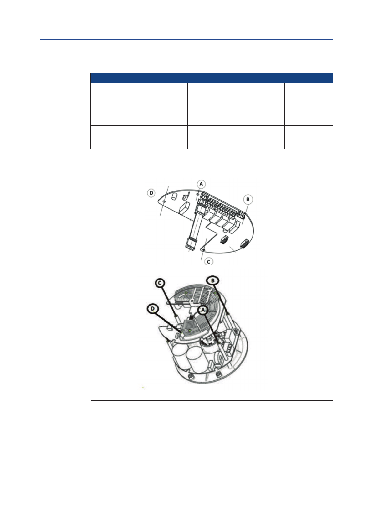
Refer to next tables and Figure 33 to choose the correct mechanical parts.
Section 5: OM1 Kits
June 2022
Figure 32
3 OFF CYLINDRICAL
METAL SPACER
1 2 3
8 9 10
3 OFF SCREWS
M3X8
4
15
1 OFF PLASTIC SPACER
1 + 3 OFF HEXAGONAL
METAL SPACER
5 6 7
11 12 13 14
3 OFF SCREWS
M3X10
16
1 OFF FLAT CONNECTOR
Table 8.
EPI2 Cross Reference Table (Non-US Market)
Actuator model Old 63-125 Old 250-2K New 63-125 New 250-2K
Product coding chart
digit X
Product coding chart
digit X
A 1, 11 11 4, 8 5, 8
B 2, 12 12 1, 11 6, 9
C 3, 13 13 2, 12 7, 10
D 14 14 15 -
1-phase
7X8
3-phase
7X8
UV - VU UV - VU LV - HV LV - HV
31, 32, 33 31, 32, 33 3A, 3B, 3C 3A, 3B, 3C
OM1 Kits
23
Page 28
Section 5: OM1 Kits
June 2022
Installation, Operation and Maintenance Manual
VCIOM-01494-EN Rev. 0
Table 9.
EPI2 Cross Reference Table (US Market)
Actuator model Old E006-E013 Old E025-E171 New E006-E013 New E025-E171
Product coding chart
digit 6 1-phase
Product coding chart
digit 6 3-phase
A 1, 11 11 4, 8 5, 8
B 2, 12 12 1, 11 6, 9
C 3, 13 13 2, 12 7, 10
D 14 14 15 -
0 - 4 0 - 4 L - H L - H
1, 2, 3 1, 2, 3 A, B, C A, B, C
Figure 33 Points A, B, C and D to Fix the Board on Standard Group
24
Figures 34 to 37 allow to distinguish old version of EPI2 from the new version (on the
labels, the digits of Product Number are boxed); furthermore, the logic boards with
heatsink identifies old version models, while logic boards without heatsink identifies
new version models.
OM1 Kits
Page 29

Installation, Operation and Maintenance Manual
VCIOM-01494-EN Rev. 0
Figure 34 Label for Non-US Market - Digits X7X8 on Product Coding Chart
Figure 35 Label for US Market - Digit 6 on Product Coding Chart
Section 5: OM1 Kits
June 2022
OM1 Kits
25
Page 30

Section 5: OM1 Kits
June 2022
Installation, Operation and Maintenance Manual
VCIOM-01494-EN Rev. 0
Figure 36 Example of EPI2 Old Version (Heatsink Present)
Figure 37 Example of EPI2 New Version (Heatsink Not Present)
26
OM1 Kits
Page 31

Installation, Operation and Maintenance Manual
VCIOM-01494-EN Rev. 0
Section 6: OM1 Wiring Diagram
Section 6: OM1 Wiring Diagram
June 2022
Figure 38
BLINKER
MONITOR RELAY RELAY
GROUND
(Note 1) Remote Commands
(Note 2, 5)
NOTES:
1) Power connection L1-L2 for V DC or V AC single phase motor supply: from 24 V to 48 V or
from 100 V to 240 V
Power connection L1-L2-L3 for 3 phase motor supply from 208 V to 575 V (Check on the
actuator label the correct voltage to be applied)
2a) Remote commands options: standard conguration
OP
CL
Internal supply 24 V DC
2b) Remote commands options: 2 wires setting (to be congured)
Contact open for actuator closing
Contact close for actuator opening
Internal supply 24 V DC
LOCAL SELECTOR
(Note 6) Output contacts
CLC1
CLC2 OPC1 OPC2
(Note 3)
Output Contacts
(Note 4)
OP
CL
External supply 24/120 V AC or 24/120 V DC
Contact open for actuator closing
Contact close for actuator opening
External supply 24/120 V AC or 24/120 V DC
J8
Optional Module OM3
3) Contacts shown in intermediate positon CLC1-CLC2 end of travel signalling in CLOSING
Contacts shown in intermediate positon OPC1-OPC2 end of travel signalling in OPENING
4) Output contact rating: 240 V AC/5 A - 30 V DC/5 A - 120 V DC/0,5 A
Output contacts (when used) have to be feed with the same external voltage
5) Control command rating: 24 to 120 V AC or V DC
Control signal: minimum duration > 600 ms
Total current drawn for remote controls < 25 mA
6) Blinker or local selector monitoring function (when mod. OM3 is present) to be congured
OPTIONAL MODULE 4 - 20 mA (OM1)
AUXC1 AUXC2 AUXC3 AUXC4
Additional contacts indipendent adjustable
along all the stroke (10 steps) (Note 8)
Retransmission
position
(Note 9) 4 - 20 mA / 0-10 V Position request
Bluetooth
(OPTIONAL)
(Note 7)
7) Position request 4 - 20 mA or 0 - 10 V to be selected on (OM1)
8) Relay output contacts can be set normally (MAKE or BREAK)
Output contact rating: 240 V AC / 5 A - 30 V DC / 5 A - 120 V DC / 0.25 A
9) Position retransmission
+24 V DC
4 - 20 mA 0 - 10 V
4 - 20 mA
24 V DC (+/- 10%)
External supply
OM1 Wiring Diagram
27
Page 32

World Area Conguration Centers (WACC) offer sales support, service,
inventory and commissioning to our global customers.
Choose the WACC or sales ofce nearest you:
NORTH & SOUTH AMERICA
19200 Northwest Freeway
Houston TX 77065
USA
T +1 281 477 4100
Av. Hollingsworth
325 Iporanga Sorocaba
SP 18087-105
Brazil
MIDDLE EAST & AFRICA
P. O. Box 17033
Jebel Ali Free Zone
Dubai
T +971 4 811 8100
P. O. Box 10305
Jubail 31961
Saudi Arabia
T +966 3 340 8650
T +55 15 3413 8888
24 Angus Crescent
ASIA PACIFIC
Longmeadow Business Estate East
P.O. Box 6908 Greenstone
No. 9 Gul Road
#01-02 Singapore 629361
T +65 6777 8211
No. 1 Lai Yuan Road
1616 Modderfontein Extension 5
South Africa
T +27 11 451 3700
EUROPE
Wuqing Development Area
Tianjin 301700
P. R. China
T +86 22 8212 3300
Holland Fasor 6
Székesfehérvár 8000
Hungary
T +36 22 53 09 50
Strada Biffi 165
29017 Fiorenzuola d’Arda (PC)
Italy
T +39 0523 944 411
For complete list of sales and manufacturing sites, please visit
www.emerson.com/actuationtechnologieslocations or contact us at
info.actuationtechnologies@emerson.com
www.emerson.com
VCIOM-01494-EN ©2022 Emerson. All rights reserved.
The Emerson logo is a trademark and service mark of Emerson Electric Co.
TM
Keystone
is a mark of one of the Emerson family of companies.
All other marks are property of their respective owners.
The contents of this publication are presented for informational purposes
only, and while every effort has been made to ensure their accuracy,
they are not to be construed as warranties or guarantees, express or
implied, regarding the products or services described herein or their use
or applicability. All sales are governed by our terms and conditions, which
are available upon request. We reserve the right to modify or improve the
designs or specifications of such products at any time without notice.
 Loading...